
 ?Mathematical formulae have been encoded as MathML and are displayed in this HTML version using MathJax in order to improve their display. Uncheck the box to turn MathJax off. This feature requires Javascript. Click on a formula to zoom.
ABSTRACT
This study presented a unique process of mechanical alloying (MA) and laser powder bed fusion (LPBF) to prepare heterogeneous grain structure (HGS) Zn with strength-plasticity synergy. The results showed that the MA-treatment significantly refined the grain sizes of Zn to nano-scale and contributed to the formation of HGS powders. Moreover, the ultra-fast heating and cooling of LPBF process inhibited the grain growth and resulted in a specific core/shell HGS, wherein the cores (micron-grains) were surrounded by interconnected shells (nano-grains). Notably, the prepared HGS Zn demonstrated synergistically improved compressive yield strength (2.1 times) and plasticity (58%) compared with the homogeneous coarse-grained counterparts. This impressive strength-plasticity synergy was primarily attributed to high back stress and dislocation pile-ups generated by the deformation incompatibility between the nano-grained shells and micron-grained cores. These findings open up new fields for MA and LPBF in the preparation of HGS metals and their applications in solving strength-plasticity tradeoff.
1. Introduction
Biodegradable Zn and Zn-based alloys have attracted great attention around the world in orthopaedic applications [Citation1–4]. Many studies have verified that they can be gradually absorbed or metabolised in human body with an appropriate degradation rate, obviating the routine for surgical removal [Citation5–7]. Moreover, as an essential trace element to human body [Citation8], Zn plays an indispensable role in bone metabolism by stimulating osteoblast bone formation while inhibiting osteoclast differentiation [Citation9, Citation10]. Nevertheless, the as-known insufficient mechanical properties of pure Zn, especially poor strength, raise uncertainties for load-bearing performance and easily lead to the premature failure of orthopaedic implants. So far, the commonly used strengthening methods for Zn mainly focus on secondary phase precipitation [Citation11, Citation12], grain refinement [Citation13, Citation14], and solid solution [Citation15, Citation16], etc. These methods have demonstrated effective roles on the mechanical strengthening of pure Zn, however, these attempts are often inevitably accompanied with significant reduction in plasticity. Similar strength-plasticity tradeoff is also prevalent in other metals, e.g. Cu [Citation17], Ti [Citation18], high-entropy alloys (HEAs) [Citation19], etc., which has long remained as a critical bottleneck for the development of high-performance alloys.
Recently, heterogeneous grain structure (HGS) alloys, consisting of hetero-zones of fine grains and coarse grains, have been developed as a promising strategy to overcome strength-plasticity tradeoff. By combining the advantages of tough fine grains and relatively ductile coarse grains, HGS can remarkably enhance the mechanical strength while retain or even improve the plasticity of alloys. Moreover, the interactions between the hetero-zones with dramatic mechanical differences can produce a synergistic effect where the integrated performance even exceeds the prediction by the rule-of-mixtures [Citation20]. According to the findings of Wu et al. [Citation18], HGS Ti sheets exhibited an exceptional combination of mechanical properties, i.e. high strength similar to that of ultrafine-grained Ti and comparable plasticity to that of coarse-grained Ti. Sawangrat et al. [Citation21] reported that HGS Cu disks showed a 26% increase in strength and a 46% increase in elongation compared to their homogeneous counterparts. These studies on Ti and Cu demonstrated the pivotal roles of HGS in synergistically improving both the strength and plasticity of metals, which provides a potential approach for addressing the strength-plasticity tradeoff of Zn.
Currently, HGS alloys are prepared mainly via ball milling followed by consolidation, usually resulting in micron-sized grains in both the coarse-grained and fine-grained regions [Citation22, Citation23]. Compared to conventional ball milling, mechanical alloying (MA) is known as an effective preparation technique for nanograined powders caused by repeated cold welding, fracturing, and re-welding processes. This stimulates a research boom for the preparation of HGS metals with coarse-grained (micron-size) and fine-grained (nano-size) regions owing to the superior mechanical strength [Citation20]. For this purpose, the MA-treated powders should undergo subsequent consolidating processes. Unfortunately, the high temperature and pressure in conventional consolidation processes can easily lead to the loss of the nano-grain structure formed during MA process. For instance, as reported by Sekiguchi et al. [Citation24], Ti powders treated by MA showed a significantly refined structure with an average grain size of ∼80 nm. However, the metastable nano-grain structure exhibited non-negligible growth (300 nm ∼ 1 μm) during the subsequent hot rolling process, leading to the loss of nano-grain structure throughout the final consolidated HGS counterparts. Therefore, it is essential to seek an appropriate consolidation process for MA-treated powders to inhibit the grain coarsening effect [Citation25].
Laser powder bed fusion (LPBF) is a consolidation technique characterised by ultra-fast heating and cooling process (up to 104 ∼ 106 K/s [Citation26–29]), in which the interaction time between laser and metal powder is extremely short [Citation30–36]. Dong et al. [Citation37] prepared pure Ti bulk metals by LPBF, using gas atomised (GA) powders (possibly consisted of micron-scaled coarse grains) and MA-treated powders (possibly consisted of ultrafine/nano grains) as raw materials, respectively. As reported, samples consolidated by the MA-treated powders exhibited a significantly finer grain structure (compared to the samples consolidated by GA powders) with massive ultrafine-grains and nanocrystalline detected. The average grain size notably reduced by twice compared to the samples consolidated by the GA powders, indicating that the refined grain structure within the powder particles could be carry over to the consolidated samples after AM processing. This demonstrates that LPBF may be qualified in inhibiting the coarsening of the nano-grain structure in MA-treated powders, thereby enabling the preparation of HGS metals with nano-grain regions. Moreover, as an additive manufacturing technique, LPBF also specialises in complex geometries and designs of orthopaedic implants that are not previously possible via traditional consolidation methods [Citation38–44]. Successful practices have been carried out on Zn and Zn-based alloys, as reported by the current studies, for example, a porous Zn scaffold was successfully prepared utilising a commercial LPBF system by Li et al [Citation45], with the unit cell size of 1.4 mm and strut thickness of 0.4 mm; as reported by Zhou et al. [Citation46], a series of Zn-x alloys (x = Al, Mg, Ce, Li, etc.) fabricated by LPBF process exhibited nearly full-dense microstructure with high consolidating precision under optimal process parameters.
In this scenario, the present work developed a combined process of MA and LPBF to prepare HGS Zn with both nano- and micro-grain structures for the first time, in order to address the strength-plasticity tradeoff of Zn. The evolutions of grain structure and particle morphology of the MA-treated powders were investigated to discover the effects of MA on HGS formation. Particularly, the shape factors and bulk properties of the MA-treated HGS powders were assessed for the subsequent LPBF process. Then the MA-treated powders were consolidated into HGS Zn counterparts with different nano-/micro-grain ratios by LPBF, and a systematic study was conducted on the evolution of grain structure. Moreover, emphasis was put on the mechanical properties of the HGS Zn, including an in-depth analysis of the enhancing mechanisms associated with grain sizes, dislocation densities, and grain boundary angles. Additionally, the corrosion behaviour of the HGS Zn was also evaluated for potential biodegradable orthopaedic applications.
2. Materials and methods
2.1. MA process
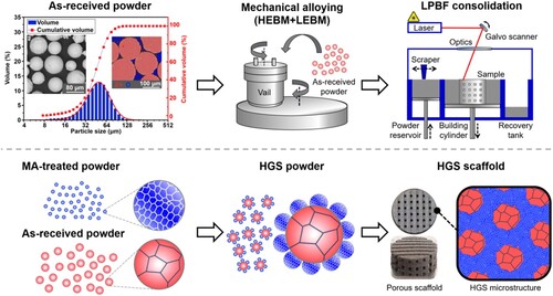
This section described the MA process for preparing HGS Zn powders with both micro- and nano-grain structures, as depicted in . The first goal was to prepare nano-grained Zn powders, and the second goal was to obtain HGS Zn powders with micro-grained inner-part surrounded by nano-grained outer-layer.
Figure 1. Characterisation of the as-received Zn powders (particle morphology, cross-sectional EDS analysis, and particle size distribution), and a schematic diagram of the combined MA and LPBF process for preparing HGS Zn.
2.1.1 Preparation of nano-grained Zn powders
Pure Zn powders (purity 99.99%, 200 mesh, Shanghai Naiou technology Co., Ltd.) in gas-atomised form were used as the raw material. The shape and size of the as-received powders were illustrated in . The Zn particles were smooth with well circularity. According to the backscatter electron (BSE) image and energy dispersive spectrometer (EDS) result, the cross-section of the particles exhibited high density with no impurity elements detected. The as-received powder also showed a Dv(50) particle size of ∼53.26 μm as measured by using a laser particle size analyzer (MS 3000, Malvern, UK).
The Zn powders were MA treated by a planetary ball mill (P-6, Fritsch, Germany) under argon atmosphere, using SUS304 balls of 6 mm in diameter and a tungsten carbide vial. The MA process was performed at a rotation speed of 350 rpm with a ball-to-powder weight ratio of 20:1. During the MA process, 10 min suspension was set between each milling period for 10 min and anhydrous ethanol was utilised as process control agent (PCA) in order to avoid severe welding. After the MA process, the powders were dried at 40°C for 6 h in a vacuum oven in order to prevent oxidation. The Zn powders were MA-treated for 4, 10, 20, 30, and 40 h, respectively.
2.1.2 Preparation of HGS Zn powders
The MA-treated Zn powders were mixed with the as-received Zn powders at different weight ratios (MA-treated Zn powders 25, 50, and 75 wt.%, respectively). The mixtures were further low-energy ball milled (LEBM) under argon atmosphere for preparing HGS Zn powders. The LEBM process was performed at a rotation speed of 100 rpm for 8 h with a ball-to-powder weight ratio of 2:1. Other milling parameters and subsequent drying process were the same as those in section 2.1.1. The HGS Zn powders were eventually obtained for the subsequent LPBF process.
2.2. LPBF consolidation
The consolidation process was conducted in a self-developed LPBF machine, where the laser beam was generated by a fibre laser (YLR-500-WC, IPG Laser, Germany) with a maximum power of 500 W. Before LPBF consolidation, all the powders were sieved using a vibratory shaker equipped with a wire sieve of 200 mesh. The sieved powders were then consolidated layer by layer on a Zn substrate with a laser spot size of ∼50 μm. Other LPBF parameters were optimised by a series of pre-experiments and were determined as follows: laser power ∼85 W, scanning speed ∼180 mm/s, scanning line interval ∼50 μm, and raster angle 90˚. The schematic diagram of the LPBF procedure was shown in , and HGS Zn samples with different weight ratios of fine-grains (25, 50, and 75 wt.%, respectively) were finally prepared and defined as HGS25, HGS50, and HGS75, respectively. In addition, the as-received Zn powders were also consolidated as control groups and defined as HGS0 in the following descriptions. It should also be pointed out that a series of LPBF pre-experiments were also carried out directly on the MA-treated Zn powders, which were found to be hardly consolidated by LPBF technique possibly due to insufficient thermostability, poor shape factors and bulk properties [Citation47–49].
2.3. Microstructure characterisation
The microstructure of the as-received Zn powders was examined by scanning electron microscopy (SEM, Pro-X, Phenom, Netherlands) equipped with EDS. To reveal the grain size, the as-received Zn powder was mounted in epoxy resin, grounded on SiC abrasive papers, polished with diamond suspensions, and then etched with ethanolic nitrate solution (4 wt.%). The grain sizes of MA-treated Zn powders were measured using a transmission electron microscope (TEM, Tecnai F20, FEI, USA). Moreover, the phase compositions of the powders were evaluated using X-ray diffraction (XRD, D8 Advance, Bruker, Germany), and the grain size evolution was further analysed based on the XRD patterns according to Debye-Scherrer Equation (1), which has been widely used in determining the size of nano-grains [Citation50, Citation51].
(1)
(1) D refers to the average grain size (Å), B is the full width at half maximum (FWHM, rad), θ is the Bragg angle (°),
is Scherrer constant (
= 0.89), and
is the wavelength of X-ray (
= 1.54056 Å).
The particle size distributions, specific surface areas and the size span (Equation (2)) of the as-received powders, MA-treated powders, and HGS powders were acquired using the aforementioned laser particle size analyzer, while BSE analysis was carried out towards the powders using SEM.
(2)
(2) where S is the size span of the powder samples,
and
represent the particle diameters with cumulative volumes of 10% and 90%, respectively, and
is the median for a volume distribution. Before BSE observation, the cross-section of HGS powders were etched with ethanolic nitrate solution (4 wt.%) for better observation of the grain sizes hence evaluating the HGS morphology within the powders. Afterwards, the aspect ratio (l/w) and circularity (Equation (3)) of the powders were measured and calculated using image analysing software Fuji ImageJ.
(3)
(3) where C is the circularity of the powder particles, A is the area (mm2) and P is the perimeter (mm) of powder particles. To evaluate the suitability for the following LPBF process, the flowability of both the as-received Zn powders and the HGS powders were measured by a Hall Flowmeter funnel according to ASTM B855-17 [Citation47]. The apparent density of the HGS powders was measured by an Arnold Meter according to ASTM B703-17 [Citation52], and the relative density was calculated from the theoretical solid density (ρsol) according to Equation (4):
(4)
(4) where
is the relative density (%),
is the apparent density (g/cm3), and
is the theoretical solid density of Zn (7.14 g/cm3).
In order to further analyse the grain structure of the HGS Zn samples after LPBF consolidation, electron back-scattered diffraction (EBSD, Zeiss evo 10, Oxford, UK) tests were carried out with a minimum scan step of 0.2 μm. The samples were polished using SiC abrasive papers (400 ∼ 2000 grit) and finished by using diamond paste (0.5 W), after which all samples were eventually electrolytic polished using 50 vol.% orthophosphoric acid under 5 V for 10 s. Thereafter, the grain size distributions, the fractions of low-angle grain boundaries (LAGBs, 2° ≤ misorientation < 15°) and high-angle grain boundaries (HAGBs, misorientation ≥ 15°), kernel average misorientation (KAM), and geometry necessary dislocation (GND) density were analysed using orientation analyzing software OIM.
For better observation of the nano-grain structure in HGS Zn, spherical aberration corrected transmission electron microscopy investigations (AC-TEM, JEM-F200, JEOL, Japan) were also carried out at an operating voltage of 200 kV. Prior to the TEM tests, the samples were first mechanically grinded and polished to a thickness of about 0.1 mm. Final thinning process was carried out in a precision ion polishing system (PIPS, Ilion 691, Gatan, USA) at the following conditions: voltage of 1 keV, and beam inclination angle of 2°.
2.4. Mechanical performance
Compression tests towards the LPBF-consolidated samples were carried out using a universal tes ting machine (ZLC-50M, Zhongluchang Testing, China) with a displacement speed of 0.5 mm/min. The samples for compression tests were column shaped with a height of 6 mm and cross-section diameter of 4 mm. Moreover, microhardness tests were carried out on a digital microhardness tester (HXD-1000TM/LCD, Taiming Optical Instrument, China) with a load of 2.94 N for a dwelling time of 15 s.
2.5. Degradation behaviour
Immersion tests have been widely utilised to investigate the long-term degradation behaviour of biomedical metals [Citation53, Citation54]. Thus, in the present study, the degradation behaviour of the LPBF-consolidated samples was evaluated by immersion tests in simulated body fluid (SBF) solution. Following the recommendation of the standard practice for the laboratory immersion corrosion testing of metals ASTM G31-72 [Citation55, Citation56], the tests was carried out at 37°C and the ratio of solution volume (ml) to sample surface area (cm2) was set at 0.2 ml/mm2. After 21 days of immersion, the corrosion products on the sample surface were removed by soaking in bichromate (200 g/L), followed by ultrasonic cleaning in anhydrous ethanol. Subsequently, the corrosion rates were calculated by measuring the dry weight of samples before the tests and after the removal of corrosion products, according to the following Equation (5),
(5)
(5) where C is the corrosion rate (mm/year), K is a constant (8.76 × 10⁴), W is the loss of weight (g), A is the surface area of sample (mm2), T is the immersion time (year), and D is the density of sample (g/cm3). In addition, the corroded surface morphology of the LPBF-consolidated samples before and after corrosion product removal were observed by SEM and an optical profilometer (WYKO NT9100, Veeco Metrology Inc., USA).
2.6. Statistical analysis
In this work, all evaluations were calculated for at least three times, and were then analysed by analysis of variance (ANOVA) using statistical software Origin. Significant differences were determined as p value < 0.05 (*).
3. Results and discussion
3.1. MA-treated zn powders
To reveal the influence of MA process on the evolution of grain structure, the as-received Zn powders were MA-treated for various durations (4, 10, 20, 30, and 40 h, respectively), and the microstructure characterisations of the resulting powders were presented in . The XRD patterns of the MA-treated powders were shown in (a), along with the standard JCPDS card of Zn (PDF No. 04-0831) as reference. As could be seen, with the increase of MA durations, the peak intensity decreased obviously and the FWHM increased, especially for the major peak Zn101 (enlarged as insert in (a)), indicating the refinement of grains. Moreover, the average grain size of the MA-treated powders was calculated from the XRD patterns using Debye-Scherrer equation, as shown in (b). After MA-treated for 4 h, the average grain size significantly decreased to 69.3 ± 15.9 nm, further demonstrating the remarkable effect of MA on grain refinement. As the MA duration increased, the grain refinement further proceeded and gradually become saturated at MA duration of 20 ∼ 40 h. The average grain size after MA-treated for 40 h was calculated to be 28.3 ± 6.8 nm. These results demonstrated the successful preparation of nano-grained Zn powders by MA treatment.
Figure 2. The structure evolution of Zn powders upon different MA durations. (a) XRD patterns of the MA-treated powders, (b) grain size vs. MA duration, (c, d) cross-sectional SEM micrographs of the as-received Zn powders, TEM analysis on the MA-treated powders for 4 h (e-h) and 30 h (i-l), respectively, (m) surface morphologies, and (n) particle size distributions. **p < 0.01, ***p < 0.001.
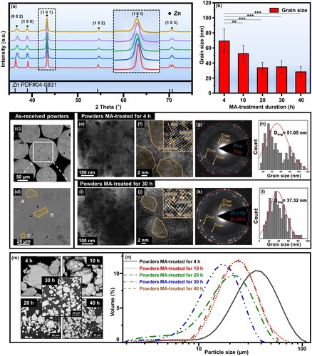
In order to observe the evolution of grain structure more intuitively, the grain morphology of the as-received and MA-treated powders were further investigated using SEM and TEM. The cross-sectional BSE micrograph of the as-received Zn powders was presented in (c), in which a majority of equiaxed grains with an average grain size of ∼20 μm could be observed inside the particles, as marked in yellow colour in the high magnification micrograph ((d)). For comparison, TEM investigations were carried out for the powders MA-treated for 4 h ((e–h)) and 30 h ((i–l)), respectively. A large number of nano-grains could be observed in the low magnification micrographs ((e and i)). And further observations by HRTEM showed finer nano-grained structure in the powders MA-treated for 30 h ((j)) as compared with that MA-treated for 4 h ((f)). In addition, the specific lattice fringes for Zn002 and Zn100 were detected in the invers fast Fourier transform (IFFT) patterns of both the MA-treated powders. In the selected area electron diffraction (SAED) patterns ((g and k)), the diffraction rings with weak and smooth appearance were found in both the MA-treated powders, further demonstrating the formation of nano-grain structure after MA-treatment [Citation57]. It was worth noting that more diffraction spots were observed on Zn112 and Zn201 after MA treatment for 30 h, indicating the possible formation of more defects and dislocations in the refined grains [Citation58]. Furthermore, the grain size distributions were also determined from TEM micrographs using digital analysing software Fuji ImageJ, as shown in (h and l). The average grain size was calculated as 51.05 nm after MA-treated 4 h and further refined to 37.32 nm when the MA duration was prolonged to 30 h.
The grain refinement towards nano-scale by MA treatment was possibly attributed to the severe collision among powder particles, milling balls, and vial. During MA process, Zn powder particles were heavily deformed, which promoted the formation of high-density dislocations. As the MA process continued, the dislocations accumulated and polygonised within Zn grains, and further tangled into dislocation cells [Citation59]. When the density of dislocation cells reached a critical value, the cell walls continuously transformed into grain boundaries, resulting in the formation of smaller grains [Citation60]. Consequently, the repeated collision during MA process led to the continuous grain refinement and the eventual formation of nano-grained structure [Citation61]. Upon a critical MA duration, the refinement process would reach a saturation level when a balance was established between the accumulation and recovery of dislocations [Citation62].
In addition to grain sizes, the evolution of particle morphology of MA-treated powders was also investigated as shown in (m). It could be observed that compared with the as-received Zn powders (), the MA-treated powders showed angular appearance with rougher surfaces. Particularly, a flattened and irregular morphology was observed for the MA-treated powders for 4 h. This could be attributed to the flat facets and irregularities caused by violent collisions with high energy among the powder particles, grinding balls, and vial [Citation63]. In comparison, regular morphology was found in the MA-treated powders for 10, 20, 30, and 40 h, respectively, especially for those particles with relatively larger sizes. Moreover, these large particles were accompanied by scattered small particles, indicating the welding and fragmenting phenomena in MA process. The particle size distributions of the MA-treated Zn powders were further investigated by the aforementioned laser particle analyzer, as shown in (n). Compared with the as-received Zn powders (), the MA-treated powders exhibited a progressive shift of particle size distribution towards smaller particle sizes for 4, 10, 20, and 30 h, while towards relatively larger particle sizes for 40 h. And the Dv(50) values were determined as 33.27, 24.68, 18.05, 15.03, and 21.72 μm, for 4, 10, 20, 30, and 40 h, respectively, which were much smaller than that of the as-received powders (53.47 μm). Moreover, similar decrease was also observed in the Dv(10) values from 15.11 to 7.15 μm, demonstrating the consecutive formation of fine particles.
It is understandable that, to ensure the structural homogeneity of subsequent HGS powders, the MA-treated powders should possess not only nano-grained structure but also small particle sizes. In the present work, the XRD and TEM analyses testified the formation of nano-grains in the powders MA-treated for different durations (4, 10, 20, 30, and 40 h, respectively), especially for those MA-treated for 20, 30, and 40 h with average grain sizes <40 nm. Moreover, the evolution of particle morphologies and size distributions exhibited the dominance of fragmenting effect upon MA treatment for 4, 10, 20, and 30 h [Citation64], followed by a tendency of coarsening as the MA time was further prolonged to 40 h. Based on the above results and discussions, the powders MA-treated for 30 h showed not only tiny nano-grained structure (34.9 ± 7.9 nm) but also the smallest particle sizes (Dv(50) = 15.03 μm), which was conducive to the structural homogeneity of core/shell regions within HGS powders. Therefore, the powders MA-treated for 30 h were finally chosen for the subsequent preparation of HGS powders.
3.2. HGS Zn powders
In order to prepare HGS Zn powders, the nano-grained powders (MA-treated for 30 h) with different weight ratios (25, 50, and 75 wt.%, respectively) were mixed and LEBM-treated with the as-received powders. The morphologies and particle size distributions of the resulting HGS powders were shown in . It could be observed from the surface morphologies ((a, d and g)) that more satellite particles were wrapped on the surface of the as-received (micron-grained) powders with the increased weight ratio of the MA-treated (nano-grained) powders, leading to gradually increased surface roughness of HGS powders. Moreover, the as-received (micron-grained) particles still maintained integrity with no fragment or welding among each other due to the LEBM process. In this scenario, HGS Zn particles were likely to be obtained with the as-received (micron-grained) particles as core regions and the MA-treated (nano-grained) particles as shell regions. In addition, the size distributions of the HGS Zn powders exhibited a shift towards smaller particle sizes with the weight ratio of the MA-treated powders increased from 25 to 75 wt.% ((b, e and h)).
Figure 3. Surface morphologies, particle size distributions, and cross-sectional micrographs of HGS powders with (a–c) 25 wt.%, (d–f) 50 wt.%, (g–i) 75 wt.% addition of MA-treated powders, respectively.
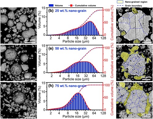
For better observation, the cross-sectional morphologies of the HGS powders were further investigated and shown in (c, f and i), in which the nano-grained regions and micron-grained regions were highlighted by yellow colour and blue lines, respectively. As could be seen, the micron- and nano-grained counterparts exhibited significant differences in appearance under BSE mode. The cross-sectional surface of the micro-grained particles showed highly dense morphology and was wrapped by tiny particles with nano-grained structure after LEBM process, indicating the formation of HGS in Zn powders. Moreover, with the increasing weight ratio of the MA-treated powders, more tiny particles were wrapped on the micro-grained particles and led to better structural homogeneity of the HGS Zn powders. These results further demonstrated the preparation of HGS in Zn powders with nano-grained particles as the outer-layer and micro-grained particles as the inner part.
For LPBF process, the quality of powders plays a crucial role in the comprehensive properties of the final consolidated part [Citation65, Citation66]. Thus, the shape factors and bulk properties of the prepared HGS Zn powders were systematically studied to evaluate the scraping and consolidating quality of the powders for LPBF process (). The shape factors including specific surface area and size span were measured by the aforementioned laser particle analyzer, while the circularity and aspect ratio were analysed based on the cross-sectional micrographs of the powders. For all the HGS powders, the aspect ratios of particles decreased with the increase of particle sizes ((a)), which was consistent with the surface morphology shown in . In comparison, the circularity of the powders exhibited an opposite trend. Concretely, relatively low circularities (0.62 ∼ 0.64) were observed in the tiny particles of all HGS powders, whereas high circularities (0.83 ∼ 0.90) were found in those relatively larger particles, which were comparable to that (0.95) of the as-received powders. As could be seen from (b), the specific surface area of the HGS powders significantly increased with the fraction of MA-treated nano-grained powders. Particularly, the largest specific surface area of 69.91 m2/kg was found in the HGS powders with 75 wt.% nano-grained powders. Compared with the as-received powders (1.1 ± 0.1), the HGS powders with different fractions of MA-treated nano-grained powders showed size span values ranging from 1.4 ± 0.1 to 2.2 ± 0.2.
Figure 4. The shape factors and bulk properties of the prepared HGS powders, (a) circularity and aspect ratio, (b) specific surface area and size span, (c) flowability, and (d) apparent density and relative density. **p < 0.01.
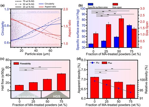
In addition, the flowability of powders is a major concern during the scraping process in LPBF [Citation66]. The flowability of the prepared HGS powders was investigated by Hall flow tests ((c)), and the results showed that the HGS powders flowed through the funnel with average times ranging from 21.4 to 44.2 s/50 g, which were somewhat inferior to that of the as-received powders (14.3 s/50 g). On the one hand, the aforementioned increased specific surface area and size span, as well as circularity variation, after MA treatment ((a,b)), had non-negligible effects on the interactions between powder particles and further the flowing and packing of powders [Citation67]. On the other hand, similar flowability results were also reported and successfully used for LPBF consolidation by many other studies [Citation68, Citation69]. For example, Parsons et al. [Citation47] prepared AlSi10Mg-TiB2 powders with flowability of 75.2 ∼ 98.1 s/50 g and evaluated the feasibility for scraping and consolidation by LPBF. They found that the powders could be spread by the scraper of LPBF machine with uniform thickness of each layer, and a high-density microstructure was achieved in the final LPBF-consolidated bulk samples. In comparison, the HGS powders prepared in the present work showed comparable or better flowability (21.4–44.2 s/50 g), which was believed to be qualified for the subsequent LPBF consolidation.
The apparent density () and relatively density (
) of the powders were also studied to further evaluate the quality of the prepared HGS powders. As shown in (d), the as-received Zn powder exhibited a nearly full-dense condition with
of 7.11 ± 0.01 g/cm3, and only slight decreases in density were observed for the HGS powders. Besides, the HGS powders also presented comparable
to the as-received powder, with a minimum
of 94.01 ± 0.01% for the HGS powder with 75 wt.% MA-treated powders. The high density of the prepared HGS powders indicated less gas inclusion within the powder particles, thereby contributing to the consolidation quality of bulk samples by LPBF [Citation47].
3.3. HGS Zn samples consolidated by LPBF
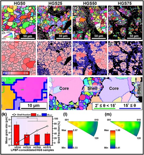
In order to evaluate the evolution of grain structure after LPBF consolidation, EBSD tests were carried out on different HGS bulk samples (). Inverse pole figure (IPF) maps overlaid with the grain boundaries of LPBF-consolidated samples were presented in (a–d). The HGS0 samples prepared by as-received powders exhibited a homogeneous grain structure with an average grain size of 6.40 ± 0.80 μm. In comparison, HGS25 samples ((b)) showed a heterogeneous microstructure wherein coarse-grains (core region) were surrounded by continuously connected fine grains (shell region). It should be noted that the black areas within the fine-grained (shell) regions were suspected to be unidentifiable nano-grains due to the limitation of the EBSD system [Citation70, Citation71]. With the increased fraction of MA-treated powders, the volume fraction of shell region in LPBF-consolidated HGS samples gradually increased, as shown in HGS50 ((c)) and HGS75 ((d)) samples, respectively. These results indicated the successful preparation of bulk HGS Zn (core/shell structure) consisting of an interconnected fine-grained network surrounded by coarse-grained regions. It is known that due to the ultrafast heating and cooling rate during LPBF consolidation, the remaining nuclei of the nanocrystalline grains (in shell regions) formed by MA treatment, together with the high nucleation rate, would result in the formation of a fine microstructure in produced parts [Citation72]. Consequently, resulted in the fine-grained structure in the interconnected shell regions. And the reason why such grain size heterogeneity formed by MA was successfully carried over to the LPBF consolidated samples was possibly attributed to the ultra-fast heating and cooling rate during LPBF process [Citation73]. In order to observe the heterogeneity of grain structure more intuitively, the core and shell regions of the IPF maps were painted in red and blue, respectively, as shown in (e–h), which further presented the core/shell structure in the LPBF-consolidated HGS Zn samples. Besides, several micro-sized grains were also observed isolatedly distributed inside the shell (blue) regions, indicating the partial grain growth during LPBF consolidation. Moreover, the high magnification EBSD characterisation using a shorter scanning step size clearly showed a homogeneous grain structure at ten or so micrometers for HGS0 sample ((i)) and a typical heterogeneous grain structure for HGS25 sample ((j)) wherein the shell region was mainly composed of fine grains at few hundred nanometers. Furthermore, the mean grain sizes and shell fractions were quantified by orientation analysing software OIM and shown in (k). It could be seen that the shell fraction of LPBF samples monotonically increased with the fraction of MA-treated powders, whereas the grain sizes within both the shell and core regions showed no statistically significant differences among the HGS samples consolidated with different fractions of MA-treated powders. In addition, the invers pole figures (IPF) of both homogeneous coarse-grained samples (HGS0, (l)) and heterogeneous grained samples (HGS25, (m)) showed relatively low texture intensities (2.07 and 1.88, respectively) along the building direction, indicating a weakened crystallographic texture, as reported in many other studies on additive manufacturing [Citation74, Citation75].
Figure 5. EBSD analysis of LPBF-consolidated HGS25, HGS50, and HGS75 samples, with HGS0 sample consolidated by the as-received powders as control. **p < 0.01.
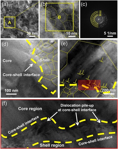
To gain insights towards the fine-grained (shell) regions in HGS Zn samples, TEM investigations ((a–c)) were further conducted on HGS50 samples as a supplement to EBSD analysis. TEM analysis ((d–f)) was also carried out on the core–shell interfaces of the HGS50 before and after compression test for exploring the possible deformation mechanisms. As shown in (a), the cross-section was filled with equiaxed grains. For a closer view, region A was further investigated using HRTEM ((b)), and the grain boundaries were distinguished and marked by yellow dashes in accordance with different lattice fringes, which exhibited major grain sizes <50 nm. The results demonstrated that a large number of nano-grains existed in the fine-grained (shell) regions, and HGS Zn with nano-grains as the shell and micro-grains as the core had been successfully prepared after the LPBF process. This was further verified by a typical polycrystalline pattern observed in the corresponding FFT of region B (42 nm × 42 nm), as shown in (c). The reason why nano/micro-grained HGS in the MA-treated powders was successfully carried over to the consolidated Zn samples was possibly attributed to the ultrafast heating and cooling rate (up to 104 ∼ 106 K/s [Citation26]) during LPBF process, which could increase the degree of undercooling and hence hinder the grain growth. Similar effects have also been reported in many other studies. For example, Han et al. [Citation72] prepared pure Al nanocrystalline powders by mechanical milling (the same as MA in our study) with average grain size below 70 nm, and discussed the subsequent application for LPBF consolidation. As reported, due to the superfast heating and cooling rate in LPBF, the remaining nuclei of the nanocrystalline Al grains, together with the high nucleation rate, results in the formation of a fine microstructure in consolidated parts. Dong et al. [Citation37] prepared pure Ti bulk metals by LPBF, using gas atomised (GA) powders (possibly consisted of micron-scaled coarse grains) and MA-treated powders (possibly consisted of ultrafine/nano grains) as raw materials, respectively. As reported, samples consolidated by the MA-treated powders exhibited a significantly finer grain structure (compared to the samples consolidated by GA powders) with massive ultrafine-grains and nanocrystalline detected. The average grain size notably reduced by twice compared to the samples consolidated by the GA powders, indicating that the refined grain structure within the powder particles could be carry over to the consolidated samples after AM processing. Moreover, it was also observed in (d) that dislocations piled up at the interfaces (marked by yellow dashes) between the nano-grain (shell) regions and micron-grain (core) regions, which might be caused by the strength heterogeneity between them.
Figure 6. TEM investigations of LPBF-consolidated HGS50 sample. (a) TEM image; (b) HRTEM image for region A; (c) FFT of region B; microstructure on the interfaces before (d) and after (e) compression test; (f) pile-up of dislocations at the core/shell interfaces.
The evolution of grain boundary angles and dislocation density of the prepared HGS Zn samples were further investigated based on the EBSD data (). As shown in the grain boundary maps ((a–d)), all the identified grain boundaries were classified into HAGBs (blue) and LAGBs (green), and the corresponding misorientation distributions were counted and presented in (e–h), for HGS0, HGS25, HGS50, and HGS75 samples, respectively. It could be seen that there were negligible differences on the fractions of HAGBs (89% ∼ 92%) among all the HGS samples, whereas the grain boundary density of both LAGBs (0.54 ∼ 3.91 × 10⁻⁸ m−1) and HAGBs (0.98 ∼ 2.34 × 10⁻⁷ m−1) significantly increased with the fraction of shell region (nano-grains). The higher density of grain boundaries may play a reinforcing role according to Hall-Patch relationship [Citation76].
Figure 7. Grain boundary and dislocation density analyses of LPBF-consolidated HGS bulk samples, with coarse-grained Zn samples consolidated by the as-received powders as control.
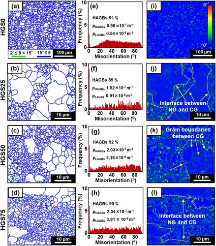
Generally, KAM is widely used to evaluate the dislocation densities for mechanical analysis of various metals [Citation77]. In the present study, a drastic change in KAM values could be observed between the coarse-grained samples ((i)) and HGS samples ((j–l)). Moreover, in the HGS samples, higher KAM values were found at the interfaces between core/shell (micron/nano-grained) regions, compared to those at the grain boundaries within the core regions. In addition, the KAM values were also used to calculate the density of GND () which was commonly regarded as an indicator for the stress distribution and thereby the mechanical strength of metals [Citation78]. It was found that the HGS samples exhibited higher
values than homogeneous coarse-grained Zn sample consolidated by the as-received powders. The higher KAM and
values indicated significant mechanical heterogeneity within the prepared HGS samples, which might contribute to the mechanical performance according to heterogeneous deformation induced (HDI) theories [Citation20].
3.4. Mechanical performance
Mechanical properties are crucial for bone implants especially for load-bearing applications, since sufficient structural support is necessary at the implant sites [Citation79–81]. For bone implant applications, compression load is considered to be the most common clinical loads of human bones [Citation82–84], especially when the body is in a vertical position. Therefore, to reveal the potential effects of HGS on the mechanical properties of Zn, compression and microhardness tests were carried out towards the LPBF-consolidated HGS Zn samples, with coarse-grained Zn samples consolidated by the as-received powders as control (). The stress–strain curves of the compression tests were presented in (a), with strain hardening curves calculated from true stress and true strain as an insert. As could be seen, the introduction of HGS exhibited a positive impact on the strength of Zn samples, especially with increasing fractions of shell regions from 0% to 50%. And a significant increase in compressive yield strength (CYS) was found in HGS50 samples (137.9 ± 10.3 MPa) compared to that of HGS0 samples with homogeneously coarse-grained structure (64.8 ± 8.2 MPa). However, a decrease in CYS was found in HGS75 samples (106.7 ± 13.1 MPa) with further increased fraction of shell regions. This might be attributed to the diminished formation quality due to the extra evaporation of the nano-grained Zn during LPBF process [Citation48, Citation85]. It is known that the CYS of human bones is considered to be 110–180 MPa according to the current studies [Citation86, Citation87]. In this study, the HGS50 Zn samples prepared by MA and LPBF combined process presented a CYS of 137.9 ± 10.3 MPa, which was within the requirements for orthopaedic implants. Moreover, as could be observed from the strain hardening curves, the HGS50 samples exhibited the highest strain hardening rate during the uniform plastic deformation, indicating relatively better plasticity. The strain hardening curves were further integrated within the uniform plastic deformation stage, and the resulting definite integral values were percentised ((b)) for quantitative analysis of the plasticity of the HGS samples, which was also utilized for plasticity comparison in many other studies [Citation18]. As could be seen, the HGS Zn samples (especially for shell fraction ≤50%) exhibited synergistic enhancements in both CYS and plasticity compared with the homogeneously coarse-grained Zn samples. To reveal the mechanical differences within the HGS samples, microhardness tests were carried out in the core and shell regions of the prepared HGS samples, respectively, and the results were presented in (c) with correlated micrographs of indentation regions as inserts. It could be seen that the shell regions (blue columns) were apparently harder than the core regions (red columns) for all HGS samples. A similar trend with CYS was found in the shell regions of HGS25 and HGS50 samples (with microhardness of 58.26 ± 4.90 HV and 83.50 ± 6.35 HV, respectively), i.e. the microhardness was improved with the increase of shell fractions.
Figure 8. (a–c) Mechanical properties of the LPBF-consolidated HGS Zn samples, with coarse-grained Zn samples as control; (d) a schematic diagram for strength-plasticity synergy mechanisms in HGS Zn; (e) the contributions from HDI strengthening, grain boundary strengthening, and dislocation strengthening. *p < 0.05.
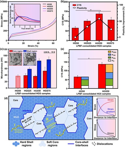
A possible schematic diagram was proposed and illustrated in (d) to explain the strength-plasticity synergy of the prepared HGS Zn samples. On the one hand, during plastic deformation, the soft-core (micron-grained) regions exhibited more plastic strain compared with the hard-shell (nano-grained) regions [Citation20]. This would lead to strain gradient near the core/shell interfaces since strain was supposed to be continuous at these interfaces. According to HDI strengthening effect, GND would occur to accommodate the strain gradient [Citation88–90], which further generated a long-range back stress near the core/shell interfaces and thereby resulted in a higher strength [Citation22, Citation91]. On the other hand, the high KAM values along the core/shell interfaces ((k)) demonstrated the strain partitioning attributed to the significant mechanical heterogeneity between the soft-core (micron-grained) and hard-shell (nano-grained) regions. According to HDI strain hardening theory, this would result in a pile-up of GND in the core regions along the core/shell interfaces ((d)), thereby contributing to better plasticity [Citation92]. As a result, the deformation propagated through the nano-grained shell regions and the micron-grained core regions by dislocation movement (as marked by label I in (d)), while the significant mechanical heterogeneity between the core and shell regions generated HDI strengthening and HDI strain hardening during deformation process, and consequently resulted in strength-plasticity synergy. Similar HDI effects were also found in other HGS metals [Citation78, Citation93]. As reported by Wu et al. [Citation18], HGS Ti exhibited high back-stress and severe GND pile-ups with the assistance of heterogeneous deformation, thereby resulting in simultaneously enhanced strength and plasticity.
Additionally, the improved plasticity might also be partially attributed to the strain-softening phenomenon [Citation94, Citation95]. It is acknowledged that metals are always subjected to strain-softening after severe plastic deformation (SPD) process. Specifically, SPD process would induce grain refinement and when the grain size was smaller than a critical value (usually 10 ∼ 15 nm [Citation95]), the deformation mechanism would transform from intragranular deformation to intergranular deformation, i.e. the deformation propagated via grain boundary sliding rather than dislocation movement [Citation95]. This would trigger strain-softening effect and thereby the improvement in plasticity [Citation96]. In the present work, the MA-treatment was also a SPD process and induced significant grain refinement of the shell regions in HGS Zn samples. Although the refinement level (<50 nm) was away from the widely reported critical value (10 ∼ 15 nm), the strain-softening effect might also occurred in the shell regions since it was pronounced in Zn and its alloys as reported by many studies [Citation97, Citation98]. For example, Guo et al. [Citation99] fabricated Zn-Mn alloys consisting of abundant nano-grains and ultrafine grains, and argued the occurrence of strain-softening effect in the multi-pass drawing process (known as a typical SPD treatment). Thus, the strain-softening might also promote the plasticity of the shell regions to a certain extent. As marked by label II in (d), the deformation would propagate quickly through the nano-grained shell regions via grain boundary sliding, which consequently contributing to the overall plasticity of the prepared HGS Zn samples.
In this regard, the strength-plasticity synergy achieved in HGS Zn could mainly be attributed to the HDI strengthening and HDI strain hardening that arose from heterogeneous deformation between micron-grained core regions and nano-grained shell regions, whereas the stain-softening effect might also play a role in the improved plasticity. It should be noted that the introduction of HGS not only induced heterogeneous deformation, but also had significant effects on grain boundaries and dislocation densities ( and ), which were also reported as important factors for mechanical performance. Therefore, the mechanical enhancement of HGS samples could be attributed to the synergy of HDI strengthening, grain boundary strengthening, and dislocation strengthening, as defined in Equation (6) [Citation100]:
(6)
(6) wherein
represents CYS,
is from the frictional stress when dislocations move along the slip plane,
is HDI stress,
and
are the contributions towards CYS from grain boundaries and dislocations, respectively. The contribution of grain boundary strengthening (
) could be calculated by Hall-Petch equation (Equation (7)) based on the grain size data obtained from :
(7)
(7) wherein
(kg/mm3/2) is the Hall-Petch coefficient related to the type and grain size of the material (specifically 0.7-1.4 for pure Zn), and
(μm) is the average grain size measured by EBSD and AC-TEM analysis. Besides, the contribution of dislocation strengthening (
) could be calculated using Taylor equation (Equation (8)):
(8)
(8) wherein
is a constant,
is Taylor factor, G is shearing modulus (GPa), b is Burgers vector, and
is calculated based on the KAM value which is obtained from the EBSD analysis. Finally, the
of the HGS50 samples could be calculated based on the following equation (Equation (9)):
(9)
(9) The contributions from the aforementioned three strengthening mechanisms were calculated and presented in (e), wherein the HGS50 samples with heterogeneous core–shell grain structure exhibited a significant increase in
(46.9 MPa) and
(34.5 MPa) compared to HGS0 samples (
= 14.1 MPa) with homogeneous coarse-grained structure. Moreover, the high strength of HGS50 Zn samples could be attributed to
,
, and
, while HDI strengthening played a dominant role among these strengthening mechanisms, followed by dislocation strengthening and grain-boundary strengthening.
In conclusion, the MA and LPBF combined process enabled the manipulation of grain structure heterogeneity by controlling the fraction of core/shell regions (micron/nano grains). According to the results, it was suggested that heterogeneities in grain structure of Zn induced HDI strengthening and HDI strain hardening due to deformation heterogeneity between the core (micron-grained) and shell (nano-grained) regions. Moreover, HGS not only induced heterogeneous deformation, but also had significant effects on grain boundaries and dislocation densities, which also contributed to the mechanical performance. Particularly, HGS50 Zn samples containing approximately 50% nano-grained shell regions exhibited a satisfying strength-plasticity synergy compared to the homogeneous coarse-grained counterpart (HGS0 samples).
3.5. Degradation behaviour
To evaluate the degradation behaviour of the HGS Zn for implant applications, the surface morphologies after immersion tests were investigated via SEM and the results were depicted in (a–d). The HGS0 samples with homogeneous coarse-grained structure exhibited a homogeneous morphology with a few degradation products situated on the corroded surface ((a)). In contrast, a rough surface morphology was found for HGS25 samples ((b)), wherein the degradation products connected into a continuous network which was similar to the specific heterogeneous grain structure observed in EBSD investigations (). With further extended fraction of shell regions, thicker degradation product layers were observed for HGS50 and HGS75 samples ((c,d)), respectively, demonstrating heavier corrosion behaviour [Citation101]. In addition, it could be speculated that the degradation products were composed of ,
,
,
, and
according to the EDS analysis and other studies [Citation102, Citation103].
Figure 9. The degradation behaviour of the LPBF-consolidated HGS Zn samples: (a–d) surface morphology with degradation products, (e–h) surface profiles after the removal of degradation products, (i) degradation rate, (j) a schematic diagram for the degradation behaviour of HGS Zn. **p < 0.01.
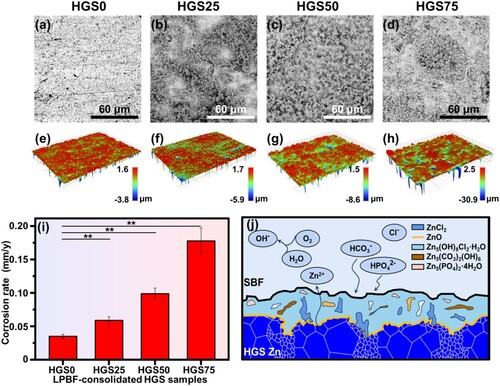
The surface profiles after the removal of corrosion products were also measured via an optical profilometer. As shown in (e–g), the HGS0, HGS25, and HGS50 samples exhibited relatively uniform surface morphologies with shallow corrosion valley. The differences mainly lay in the areas of different colours, which might relate to the fractions of shell regions in the HGS samples, i.e. the areas of degradation were broadened with the increase of shell fraction. In addition, there were very slight changes in the height differences of the three samples. In contrast, the corroded surfaces of HGS75 samples showed aggravated corrosion with significantly increased height fluctuations ((h)), which might be caused by the high fraction of nano-grained regions and diminished sample quality in LPBF.
After immersed for 21 days, the average degradation rates were calculated from the weight loss of the samples and the results were shown in (i). Obviously, the degradation rate increased with the fraction of shell regions, which was consistent with the surface morphologies after immersion tests. Specifically, the degradation rates of HGS25 (0.059 ± 0.006 mm/y), HGS50 (0.098 ± 0.008 mm/y), and HGS75 (0.178 ± 0.019 mm/y) samples were found to be 1.7, 2.8, and 5.1 times, respectively, higher than that of the HGS0 samples (0.035 ± 0.003 mm/y).
It was reported that biodegradable implants should be sustained for 12 ∼ 24 weeks depending on different clinical conditions to guarantee the bone healing process, during which the implants should synchronously degrade [Citation104, Citation105]. It was reported that the suitable degradation rate was considered to be 0.2 ∼ 0.5 mm/y for bone implants [Citation106, Citation107]. And other studies found that the degradation rate of pure Zn implants was 0.070 ∼ 0.085 mm/y which was relatively suitable compared with other biodegradable metals (e.g. Mg and Fe), however, still slow for bone implant applications [Citation108, Citation109]. Specifically in the present study, the degradation rates of HGS25 (0.059 ± 0.006 mm/y), HGS50 (0.098 ± 0.008 mm/y), and HGS75 (0.178 ± 0.019 mm/y) samples were found to be 1.7, 2.8, and 5.1 times, respectively, higher than that of HGS0 samples (0.035 ± 0.003 mm/y). The results of the present study indicated that the accelerated degradation rates of HGS samples were much closer to the bone healing rate but still slower than it. Anyway, this study has provided a novel approach for the degradation adaptation of Zn-based implants, and new design and development of HGS structure are necessary to further modulate their degradation rates for bone implant applications.
The possible degradation mechanisms for the HGS Zn were illustrated in (j). On the one hand, for HGS 25 and HGS 50 samples in the present study, at the initial stage of immersion process, a preferential degradation occurred in the fine-grained shell regions. Similar accelerated degradation behaviour was also found by other studies [Citation109, Citation110]. It has been found that pure Zn with finer grain size showed higher corrosion rate (3 times compared to the coarse-grained samples) after grain refinement, which was explained by the relatively higher energy in the grain boundaries where the defects accumulated [Citation110]. Moreover, it has been reported that pure Zn with finer grain size (consolidated by LPBF) exhibited a higher degradation rate, which might be attributed to the activation of the grain boundaries [Citation109]. This led to the more and rapid exposure of contact surface area in the core regions with body fluids, which inevitably accelerated the degradation of core regions and thereby the overall degradation of HGS Zn samples. Moreover, the degradation process would be slowed down due to the stable oxide and thermodynamically-stabled insoluble phosphate (e.g. Zn3(PO4)2·4H2O) formed on the surface of the samples as the degradation process continued [Citation109]. Therefore, it is estimated that the degradation rate would be slowed down with further elapse of the immersion time. On the other hand, regarding HGS75 in the present study, the relatively higher degradation rate could be explained by the following reasons. The degradation behaviour could be affected by other factors, not limited to impurity, fabrication methods and surface defects [Citation110]. The existence of tiny defects on the surface of the LPBF consolidated HGS Zn samples became the sources of pit corrosion during the immersion process, hence resulted in the rapid degradation. In addition, a series of degradation products could be generated during the degradation process according to related studies (Equations (9)–(19)) [Citation102, Citation103].
(9)
(9)
(10)
(10)
(11)
(11)
(12)
(12)
(13)
(13)
(14)
(14)
(15)
(15)
(16)
(16)
(17)
(17)
(18)
(18)
(19)
(19)
In the present study, Zn with heterogeneous grain structure was prepared by a combined route of MA and LPBF. Notably, the prepared HGS Zn demonstrated synergistically improved compressive yield strength up to 137.9 MPa (2.1 times to that of Zn with homogeneous coarse-grained structure) and plasticity (58%) compared with the homogeneous coarse-grained counterparts. The improved mechanical properties were comparable to the requirements for clinical bone implants [Citation111, Citation112]. Yang et al. [Citation113] prepared Zn-5HA composites by SPS with a compressive strength of ∼110 MPa and the composite was inserted into the femur condyle of rats for further investigations. The in vivo tests demonstrated that Zn-5HA composites were able to maintain mechanical integrity for more than 8 weeks which was critically important for bone healing process [Citation114]. Bowen et al. [Citation115] prepared Zn-5Al alloys with significantly enhanced YS (240 MPa) and good in vivo performance, whereas the plasticity was reduced by twice compared to pure Zn control. In comparison, HGS Zn prepared in the current study exhibited better strength-plasticity synergy, indicating potential applications for clinical bone repair.
Recently, several studies have been carried out focusing on the degradation behaviour of Zn-based metals for bone implant applications. For example, Zheng et al. [Citation108] prepared Zn-1Mg alloy for bone implant applications by extrusion, and the degradation behaviour was evaluated by in vivo analysis in mouse femora. As reported, the in vivo and in vitro degradation rate of the as-prepared Zn-1Mg were accelerated to 0.17 and 0.08 mm/y, respectively, compared with pure Zn control, and the promoted bone formation ability and good in vivo biological compatibility of Zn-1Mg were also verified. Zn-HA metal matrix composite was prepared by Yang et al. using SPS [Citation113]. As reported, moderate in vivo degradation behaviour and adjustable degradation rates (0.003 ∼ 0.025 mm/y) were found to be attributed to the biphasic effects of HA. In the present study, HGS endowed Zn with accelerated and controllable degradation behaviour by heterogeneous corrosion between the fine-grained shell regions and coarse-grained core regions. To be specific, the degradation rates of HGS25 (0.059 ± 0.006 mm/y), HGS50 (0.098 ± 0.008 mm/y), and HGS75 (0.178 ± 0.019 mm/y) samples were found to be 1.7, 2.8, and 5.1 times, respectively, higher than that of the HGS0 samples (0.035 ± 0.003 mm/y). Compared with pure Zn group and the Zn-based materials reported by other studies, the accelerated degradation rates of HGS Zn in the present study were much closer to the required degradation rate for bone implants (reported to be 0.2 ∼ 0.5 mm/y) but still slower than it. As a consequence, it is believed that the HGS Zn prepared in the present study exhibited potential application as bone implants, whereas further studies of heterogeneous grain structures are still indispensable towards modulating the degradation behaviour for better adaption.
Moreover, as an essential trace element to human body, Zn plays an indispensable role in bone metabolism by stimulating osteoblast bone formation while inhibiting osteoclast differentiation [Citation10]. Furthermore, many studies also showed various comprehensive biofunctions of Zn, not limit to antibacterial activity and immunity enhancement [Citation116]. Therefore, it can be speculated that the HGS Zn prepared by MA and LPBF process in this study also possessed appropriate in vivo biosafety, since no harmful alloying element or second phases were introduced.
4. Conclusions
The present study proposed a combined MA and LPBF process to prepare nano-/micron-grained heterogeneous Zn, in order to address the strength-plasticity tradeoff. And the following conclusions can be obtained:
The MA-treatment induced significant grain refinement to nano-scale in Zn particles, and contributed to the formation of heterogeneous Zn powders with nano-grained particles as the outer-layer and micron-grained particles as the inner part.
LPBF process effectively inhibited the grain growth due to the ultra-fast heating and cooling rate, and thereby achieved a specific HGS with core regions (micron-grained) surrounded by the interconnected shell regions (nano-grained) in the consolidated Zn samples. Moreover, the grain structure heterogeneity could be manipulated by controlling the fraction of core/shell regions.
The grain heterogeneity in HGS Zn triggered heterogeneous deformation between the core and shell regions, leading to strength-plasticity synergy. Consequently, the HGS50 Zn samples presented a synergistically improved CYS (2.1 times) and plasticity (58%) compared with the homogeneous coarse-grained counterparts.
The HGS Zn samples also showed accelerated degradation which might be caused by the degradation differences between the core and shell regions.
Overall, the HGS Zn prepared by MA and LPBF showcased the potential to address the strength-plasticity tradeoff as well as regulate the degradation behaviour, which may provide valuable insights into the development of high-performance Zn for biomedical applications.
Disclosure statement
No potential conflict of interest was reported by the author(s).
Data availability statement
The data that support the findings of this study are available from the corresponding author upon reasonable request.
Additional information
Funding
References
- Zheng YF, Gu XN, Witte F. Biodegradable metals. Mater Sci Eng R-Rep. 2014;77:1–34. doi:10.1016/j.mser.2014.01.001
- Shi Z, Li Z, Bai W, et al. (Fe, Mn)Zn13 phase and its core-shell structure in novel biodegradable Zn-Mn-Fe alloys. Mater Des. 2019;162:235–245. doi:10.1016/j.matdes.2018.11.057
- Li HF, Shi ZZ, Wang LN. Opportunities and challenges of biodegradable Zn-based alloys. J Mater Sci Technol. 2020;46:136–138. doi:10.1016/j.jmst.2019.12.014
- Yuan W, Xia D, Wu S, et al. A review on current research status of the surface modification of Zn-based biodegradable metals. Bioact Mater. 2022;7:192–216. doi:10.1016/j.bioactmat.2021.05.018
- Bowen PK, Drelich J, Goldman J. Zinc exhibits ideal physiological corrosion behavior for bioabsorbable stents. Adv Mater. 2013;25:2577–2582. doi:10.1002/adma.201300226
- Su Y, Cockerill I, Wang Y, et al. Zinc-based biomaterials for regeneration and therapy. Trends Biotechnol 2019;37:428–441. doi:10.1016/j.tibtech.2018.10.009
- Ma J, Niu L, Yan Y, et al. Influence of heat treatment on microstructure and electrochemical behaviors of Mg-Zn binary alloys prepared by gas-phase alloying technique. J Cent South Univ. 2020;27:762–771. doi:10.1007/s11771-020-4329-7
- Stefanidou M, Maravelias C, Dona A, et al. Zinc: a multipurpose trace element. Arch Toxicol 2006;80:1–9. doi:10.1007/s00204-005-0009-5
- Huang X, Huang D, Zhu T, et al. Sustained zinc release in cooperation with CaP scaffold promoted bone regeneration via directing stem cell fate and triggering a pro-healing immune stimuli. J Nanobiotechnology. 2021;19:207. doi:10.1186/s12951-021-00956-8
- Jia B, Yang H, Han Y, et al. In vitro and in vivo studies of Zn-Mn biodegradable metals designed for orthopedic applications. Acta Biomater. 2020;108:358–372. doi:10.1016/j.actbio.2020.03.009
- Yue R, Zhang J, Ke G, et al. Effects of extrusion temperature on microstructure, mechanical properties and in vitro degradation behavior of biodegradable Zn-3Cu-0.5Fe alloy. Mater Sci Eng: C. 2019;105:110106. doi:10.1016/j.msec.2019.110106
- Tang Z, Huang H, Niu J, et al. Design and characterizations of novel biodegradable Zn-Cu-Mg alloys for potential biodegradable implants. Mater Des. 2017;117:84–94. doi:10.1016/j.matdes.2016.12.075
- Zhu X, Ren T, Guo P, et al. Strengthening mechanism and biocompatibility of degradable Zn-Mn alloy with different Mn content. Mater Today Commun. 2022;31:103639. doi:10.1016/j.mtcomm.2022.103639
- Bednarczyk W, Kawałko J, Wątroba M, et al. Microstructure and mechanical properties of a Zn-0.5Cu alloy processed by high-pressure torsion. Mater Sci Eng A. 2020;776:139047. doi:10.1016/j.msea.2020.139047
- Chen C, Fan S, Niu J, et al. Alloying design strategy for biodegradable zinc alloys based on first-principles study of solid solution strengthening. Mater Des. 2021;204:109676. doi:10.1016/j.matdes.2021.109676
- Li W, Dai Y, Zhang D, et al. Biodegradable Zn–0.5Li alloys with supersaturated solid solution—aging treatment for implant applications. J Mater Res Technol. 2023;24:9292–9305. doi:10.1016/j.jmrt.2023.05.136
- Lu L, Shen YF, Chen XH, et al. Ultrahigh strength and high electrical conductivity in copper. Science. 2004;304:422–426. doi:10.1126/science.1092905
- Wu XL, Yang MX, Yuan FP, et al. Heterogeneous lamella structure unites ultrafine-grain strength with coarse-grain ductility. Proc Natl Acad Sci USA 2015;112:14501–14505.
- Lin D, Xi X, Ma R, et al. Fabrication of a strong and ductile FeCoCrNiMo0.3 high-entropy alloy with a micro-nano precipitate framework via laser powder bed fusion. Compos B: Eng. 2023;266:111006. doi:10.1016/j.compositesb.2023.111006
- Zhu Y, Wu X. Heterostructured materials. Prog Mater Sci. 2023;131:101019. doi:10.1016/j.pmatsci.2022.101019
- Sawangrat C, Kato S, Orlov D, et al. Harmonic-structured copper: performance and proof of fabrication concept based on severe plastic deformation of powders. J Mater Sci. 2014;49:6579–6585. doi:10.1007/s10853-014-8258-4
- Zhang Z, Vajpai SK, Orlov D, et al. Improvement of mechanical properties in SUS304L steel through the control of bimodal microstructure characteristics. Mater Sci Eng A. 2014;598:106–113. doi:10.1016/j.msea.2014.01.023
- Kikuchi S, Mori T, Kubozono H, et al. Evaluation of near-threshold fatigue crack propagation in harmonic-structured CP titanium with a bimodal grain size distribution. Eng Fract Mech. 2017;181:77–86. doi:10.1016/j.engfracmech.2017.06.026
- Sekiguchi T, Ono K, Fujiwara H, et al. New microstructure design for commercially pure titanium with outstanding mechanical properties by mechanical milling and Hot roll sintering. Mater Trans. 2010;51:39–45. doi:10.2320/matertrans.MB200913
- Tsuchiyama T, Hamamoto S, Nakashima K, et al. Microstructure of fine-grained β-type titanium alloy produced by mechanical alloying and consolidation process. Mater Sci Eng A. 2008;474:120–127. doi:10.1016/j.msea.2007.03.104
- Wang XQ, Carter LN, Pang B, et al. Microstructure and yield strength of SLM-fabricated CM247LC Ni-Superalloy. Acta Mater. 2017;128:87–95. doi:10.1016/j.actamat.2017.02.007
- Zhu YZ, Joralmon D, Shan WT, et al. 3D printing biomimetic materials and structures for biomedical applications. Bio-Des Manuf. 2021;4:405–428. doi:10.1007/s42242-020-00117-0
- Zhang C, Zhu H, Hu Z, et al. A comparative study on single-laser and multi-laser selective laser melting AlSi10Mg: defects, microstructure and mechanical properties. Mater Sci Eng A. 2019;746:416–423. doi:10.1016/j.msea.2019.01.024
- Li Z, Li H, Zhu X, et al. Directly printed embedded metal mesh for flexible transparent electrode via liquid substrate electric-field-driven Jet. Adv Sci. 2022;9:2105331. doi:10.1002/advs.202105331
- Gu D, Guo M, Zhang H, et al. Effects of laser scanning strategies on selective laser melting of pure tungsten. Int J Extreme Manuf. 2020;2:025001. doi:10.1088/2631-7990/ab7b00
- Wei C, Gu H, Gu YC, et al. Abnormal interfacial bonding mechanisms of multi-material additive-manufactured tungsten-stainless steel sandwich structure. Int J Extreme Manuf. 2022;4:025002.
- E. Santecchia, S. Spigarelli, M. Cabibbo, Material reuse in laser powder bed fusion: side effects of the laser—metal powder interaction. 2020.
- Xie D, Lv F, Shen L, et al. Effect of higher laser power remelting on porosity and mechanical performance of part built by laser powder bed fusion. Int J Adv Manuf Technol. 2023;125:4779–4791. doi:10.1007/s00170-023-11067-z
- Xi X, Lin D, Song X, et al. Strength-plasticity transition mechanism after the solution treatment of GH3230 superalloy fabricated via laser powder bed fusion. Mater Sci Eng A. 2023;876:145124. doi:10.1016/j.msea.2023.145124
- Chen C, Li S, Ling C, et al. Laser printed amorphous magnesium alloy: microstructure, mechanical properties and degradation behavior. J Mater Res Technol. 2023;27:6961–6973. doi:10.1016/j.jmrt.2023.11.095
- Shuai C, Xie J, Jiang X, et al. Additively manufactured high entropy alloy with high wear resistance for biomedical implant. Vacuum. 2024;221:112939. doi:10.1016/j.vacuum.2023.112939
- Dong YP, Tang JC, Wang DW, et al. Additive manufacturing of pure Ti with superior mechanical performance, low cost, and biocompatibility for potential replacement of Ti-6Al-4V. Mater Des. 2020;196:109142. doi:10.1016/j.matdes.2020.109142
- Lin D, Xi X, Yan M, et al. Significantly improved weldability in laser welding of additively manufactured Haynes 230 superalloys by tailoring microstructure. J Mater Res Technol. 2023;26:7873–7892. doi:10.1016/j.jmrt.2023.09.134
- Shuai C, Shi X, Yang F, et al. Oxygen vacancy boosting Fenton reaction in bone scaffold towards fighting bacterial infection. Int J Extreme Manuf. 2024;6:015101. doi:10.1088/2631-7990/ad01fd
- Nouri A, Rohani Shirvan A, Li Y, et al. Additive manufacturing of metallic and polymeric load-bearing biomaterials using laser powder bed fusion: a review. J Mater Sci Technol. 2021;94:196–215. doi:10.1016/j.jmst.2021.03.058
- Qi F, Liao R, Wu P, et al. An electrical microenvironment constructed based on electromagnetic induction stimulates neural differentiation. Mater Chem Front. 2023;7:1671–1683. doi:10.1039/D2QM01193J
- Feng P, Zhao R, Yang F, et al. Co-continuous structure enhanced magnetic responsive shape memory PLLA/TPU blend fabricated by 4D printing. Virtual Phys Prototyp. 2024;19:e2290186. doi:10.1080/17452759.2023.2290186
- Ferretto I, Kim D, Della Ventura NM, et al. Laser powder bed fusion of a Fe–Mn–Si shape memory alloy. Addit Manuf. 2021;46:102071. doi:10.1016/j.addma.2021.102071
- Shuai C, Wang K, Peng S, et al. Accelerating Ce3+/Ce4+ conversion in CeO2 via Mn doping to endow scaffolds with chemodynamic therapy properties. Surf Interfaces. 2024;45:103846. doi:10.1016/j.surfin.2024.103846
- Li Y, Pavanram P, Zhou J, et al. Additively manufactured biodegradable porous zinc. Acta Biomater. 2020;101:609–623. doi:10.1016/j.actbio.2019.10.034
- Zhou Y, Wang J, Yang Y, et al. Laser additive manufacturing of zinc targeting for biomedical application. Int J Bioprinting. 2021;8:501. doi:10.18063/ijb.v8i1.501
- Parsons EM, Shaik SZ. Additive manufacturing of aluminum metal matrix composites: Mechanical alloying of composite powders and single track consolidation with laser powder bed fusion. Addit Manuf. 2022;50:102450. doi:10.1016/j.addma.2021.102450
- Qin Y, Liu J, Chen Y, et al. Influence of laser energy input and shielding gas flow on evaporation fume during laser powder bed fusion of Zn metal. 2021.
- Peng HR, Gong MM, Chen YZ, et al. Thermal stability of nanocrystalline materials: thermodynamics and kinetics. Int Mater Rev. 2017;62:303–333.
- Ma XF, Sun YN, Cheng WJ, et al. Effect of high-speed laser cladding on microstructure and corrosion resistance of CoCrFeNiMo0.2 high-entropy alloy. J Cent South Univ. 2022;29:3436–3446. doi:10.1007/s11771-022-5162-y
- Zhang CY, Lan C, Lin JJ, et al. In vitro evaluation of degradation, cytocompatibility and antibacterial property of polycaprolactone/hydroxyapatite composite coating on bioresorbable magnesium alloy. J Magnes Alloys. 2022;10:2252–2265. doi:10.1016/j.jma.2021.07.014
- Craig O, Bois-Brochu A, Plucknett K. Geometry and surface characteristics of H13 hot-work tool steel manufactured using laser-directed energy deposition. Int J Adv Manuf Technol. 2021;116:699–718. doi:10.1007/s00170-021-07322-w
- Kirkland NT, Birbilis N, Staiger MP. Assessing the corrosion of biodegradable magnesium implants: a critical review of current methodologies and their limitations. Acta Biomater. 2012;8:925–936. doi:10.1016/j.actbio.2011.11.014
- Zadpoor AA. Relationship between in vitro apatite-forming ability measured using simulated body fluid and in vivo bioactivity of biomaterials. Mater Sci Eng C Mater Biol Appl. 2014;35:134–143. doi:10.1016/j.msec.2013.10.026
- Zhang S, Zhang X, Zhao C, et al. Research on an Mg–Zn alloy as a degradable biomaterial. Acta Biomater. 2010;6:626–640. doi:10.1016/j.actbio.2009.06.028
- Ibrahim AMH, Balog M, Krizik P, et al. Partially biodegradable Ti-based composites for biomedical applications subjected to intense and cyclic loading. J Alloys Compd. 2020;839:155663. doi:10.1016/j.jallcom.2020.155663
- Yoshitake T, Hara T, Fukugawa T, et al. Low-Temperature growth of nanocrystalline diamond by reactive pulsed laser deposition under a hydrogen atmosphere. Jpn J Appl Phys. 2004;43:L240. doi:10.1143/JJAP.43.L240
- Liu H, Wang Y, Li B, et al. Effect of cryogenic rolling process on microstructure and mechanical properties of Mg-14Li-1Al alloy. Mater Charact. 2019;157:109903. doi:10.1016/j.matchar.2019.109903
- Dercz G, Matuła I, Zubko M, et al. Synthesis of porous Ti–50Ta alloy by powder metallurgy. Mater Charact. 2018;142:124–136. doi:10.1016/j.matchar.2018.05.033
- Yu H, Sun Y, Hu L, et al. Microstructural evolution of AZ61-10at.%Ti composite powders during mechanical milling. Mater Des. 2016;104:265–275. doi:10.1016/j.matdes.2016.05.014
- Han L, Liu J, Tang H, et al. Study of Zr addition on the composition, crystallite size, microstructure and properties of high-performance nano Cu alloys prepared by mechanical alloying. Mater Chem Phys. 2022;290:126630. doi:10.1016/j.matchemphys.2022.126630
- Suryanarayana C, Al-Joubori AA, Wang Z. Nanostructured materials and nanocomposites by mechanical alloying: an overview. Met Mater Int. 2022;28:41–53. doi:10.1007/s12540-021-00998-5
- Tjong SC, Chen H. Nanocrystalline materials and coatings. Mater Sci Eng: R. Rep. 2004;45:1–88.
- Fogagnolo JB, Velasco F, Robert MH, et al. Effect of mechanical alloying on the morphology, microstructure and properties of aluminium matrix composite powders. Mater Sci Eng A. 2003;342:131–143. doi:10.1016/S0921-5093(02)00246-0
- Qi F, Wang Z, Yang L, et al. A collaborative CeO2@metal-organic framework nanosystem to endow scaffolds with photodynamic antibacterial effect. Materials Today Chemistry. 2023;27:101336. doi:10.1016/j.mtchem.2022.101336
- Vock S, Klöden B, Kirchner A, et al. Powders for powder bed fusion: a review. Prog Addit Manuf. 2019;4:383–397. doi:10.1007/s40964-019-00078-6
- Gao MZ, Ludwig B, Palmer TA. Impact of atomization gas on characteristics of austenitic stainless steel powder feedstocks for additive manufacturing. Powder Technol. 2021;383:30–42. doi:10.1016/j.powtec.2020.12.005
- Brika SE, Letenneur M, Dion CA, et al. Influence of particle morphology and size distribution on the powder flowability and laser powder bed fusion manufacturability of Ti-6Al-4V alloy. Addit Manuf. 2020;31:100929. doi:10.1016/j.addma.2019.100929
- Mosallanejad MH, Niroumand B, Aversa A, et al. In-situ alloying in laser-based additive manufacturing processes: a critical review. J Alloys Compd. 2021;872:159567. doi:10.1016/j.jallcom.2021.159567
- Wright SI, Nowell MM, Field DP. A review of strain analysis using electron backscatter diffraction. Microsc Microanal. 2011;17:316–329. doi:10.1017/S1431927611000055
- Fullwood DT, Sanderson S, Baird S, et al. Determining grain boundary position and geometry from EBSD data: limits of accuracy. Microsc Microanal. 2022;28:96–108. doi:10.1017/S1431927621013611
- Han Q, Setchi R, Evans SL. Characterisation and milling time optimisation of nanocrystalline aluminium powder for selective laser melting. Int J Adv Manuf Technol. 2017;88:1429–1438. doi:10.1007/s00170-016-8866-z
- Gao C, Yao X, Deng Y, et al. Laser-beam powder bed fusion followed by annealing with stress: a promising route for magnetostrictive improvement of polycrystalline Fe81Ga19 alloys. Addit Manuf. 2023;68:103516. doi:10.1016/j.addma.2023.103516
- Hagihara K, Nakano T. Control of anisotropic crystallographic texture in powder Bed fusion additive manufacturing of metals and ceramics—a review. JOM. 2022;74:1760–1773. doi:10.1007/s11837-021-04966-7
- Nadammal N, Mishurova T, Fritsch T, et al. Critical role of scan strategies on the development of microstructure, texture, and residual stresses during laser powder bed fusion additive manufacturing. Addit Manuf. 2021;38:101792. doi:10.1016/j.addma.2020.101792
- Xu W, Zhang B, Du K, et al. Thermally stable nanostructured Al-Mg alloy with relaxed grain boundaries. Acta Mater. 2022;226:117640. doi:10.1016/j.actamat.2022.117640
- Guglielmi PO, Ziehmer M, Lilleodden ET. On a novel strain indicator based on uncorrelated misorientation angles for correlating dislocation density to local strength. Acta Mater. 2018;150:195–205. doi:10.1016/j.actamat.2018.03.009
- He J, Yuan F, Yang M, et al. Exceptional tensile properties under cryogenic temperature in heterogeneous laminates induced by non-uniform martensite transformation and strain delocalization. Mater Sci Eng A. 2020;791:139780. doi:10.1016/j.msea.2020.139780
- Zhang B, Pei X, Zhou C, et al. The biomimetic design and 3D printing of customized mechanical properties porous Ti6Al4V scaffold for load-bearing bone reconstruction. Mater Des. 2018;152:30–39. doi:10.1016/j.matdes.2018.04.065
- Carluccio D, Xu C, Venezuela J, et al. Additively manufactured iron-manganese for biodegradable porous load-bearing bone scaffold applications. Acta Biomater. 2020;103:346–360. doi:10.1016/j.actbio.2019.12.018
- Qi F, Li H, Gao X, et al. Oxygen vacancy healing boosts the piezoelectricity of bone scaffolds, Biomaterials Science. 2024.
- Mroz TE, Lin EL, Summit MC, et al. Biomechanical analysis of allograft bone treated with a novel tissue sterilization process. Spine J: Off J N Am Spine Soc. 2006;6:34–39. doi:10.1016/j.spinee.2005.10.007
- Mabrouk M, Mousa SM, Abd ElGhany WA, et al. Bioactivity and cell viability of Ag+- and Zr4+-co-doped biphasic calcium phosphate. Appl Phys A-Mater Sci Process. 2021;127:948. doi:10.1007/s00339-021-05051-1
- Pitzen T, Tan JS, Dvorak MF, et al. Local autograft retrieval from a cervical vertebral body: biomechanical consequences. J Neurosurg-Spine. 2012;16:340–344. doi:10.3171/2011.12.SPINE11677
- Wen P, Qin Y, Chen Y, et al. Laser additive manufacturing of Zn porous scaffolds: shielding gas flow, surface quality and densification. J Mater Sci Technol. 2019;35:368–376. doi:10.1016/j.jmst.2018.09.065
- Huttunen M, Ashammakhi N, Törmälä P, et al. Fibre reinforced bioresorbable composites for spinal surgery. Acta Biomater. 2006;2:575–587. doi:10.1016/j.actbio.2006.03.008
- Zhou YL, Luo DM, Hu WY, et al. Compressive properties of hot-rolled Mg-Zr-Ca alloys for biomedical applications. Adv Mat Res. 2011;197-198-198:56–59. doi:10.4028/www.scientific.net/AMR.197-198.56
- Ma X, Huang C, Moering J, et al. Mechanical properties of copper/bronze laminates: role of interfaces. Acta Mater. 2016;116:43–52. doi:10.1016/j.actamat.2016.06.023
- Ma XL, Huang CX, Xu WZ, et al. Strain hardening and ductility in a coarse-grain/nanostructure laminate material. Scr Mater. 2015;103:57–60. doi:10.1016/j.scriptamat.2015.03.006
- Beyerlein IJ, Mayeur JR, Zheng S, et al. Emergence of stable interfaces under extreme plastic deformation. Proc Natl Acad Sci USA. 2014;111:4386–4390. doi:10.1073/pnas.1319436111
- Park HK, Ameyama K, Yoo J, et al. Additional hardening in harmonic structured materials by strain partitioning and back stress. Mater Res Lett. 2018;6:261–267. doi:10.1080/21663831.2018.1439115
- Liu J, Chen Z, Zhang F, et al. Simultaneously increasing strength and ductility of nanoparticles reinforced Al composites via accumulative orthogonal extrusion process. Mater Res Lett. 2018;6:406–412. doi:10.1080/21663831.2018.1471421
- Liu Y, Cao Y, Mao Q, et al. Critical microstructures and defects in heterostructured materials and their effects on mechanical properties. Acta Mater. 2020;189:129–144. doi:10.1016/j.actamat.2020.03.001
- Huang H, Li G, Jia Q, et al. Recent advances on the mechanical behavior of zinc based biodegradable metals focusing on the strain softening phenomenon. Acta Biomater. 2022;152:1–18. doi:10.1016/j.actbio.2022.08.041
- Hu J, Shi YN, Sauvage X, et al. Grain boundary stability governs hardening and softening in extremely fine nanograined metals. SCIENCE. 2017;355:1292–1296. doi:10.1126/science.aal5166
- Edalati K, Horita Z, Valiev RZ. Transition from poor ductility to room-temperature superplasticity in a nanostructured aluminum alloy. Sci Rep. 2018;8:6740.doi:10.1038/s41598-018-25140-1
- Zhao S, Seitz J, Eifler R, et al. Zn-Li alloy after extrusion and drawing: structural, mechanical characterization, and biodegradation in abdominal aorta of rat. Mater Sci Eng: C. 2017;76:301–312. doi:10.1016/j.msec.2017.02.167
- Ren K, Zhang K, Zhang Y, et al. Effect of ECAP temperature on formation of triple heterogeneous microstructure and mechanical properties of Zn–1Cu alloy. Mater Sci Eng A. 2021;826:141990. doi:10.1016/j.msea.2021.141990
- Guo P, Zhu X, Yang L, et al. Ultrafine- and uniform-grained biodegradable Zn-0.5Mn alloy: Grain refinement mechanism, corrosion behavior, and biocompatibility in vivo. Mater Sci Eng: C. 2021;118:111391. doi:10.1016/j.msec.2020.111391
- Srinivasarao B, Oh-ishi K, Ohkubo T, et al. Bimodally grained high-strength Fe fabricated by mechanical alloying and spark plasma sintering. Acta Mater. 2009;57:3277–3286. doi:10.1016/j.actamat.2009.03.034
- Enestam S, Bankiewicz D, Tuiremo J, et al. Are NaCl and KCl equally corrosive on superheater materials of steam boilers? FUEL. 2013;104:294–306. doi:10.1016/j.fuel.2012.07.020
- Liu X, Yang H, Liu Y, et al. Comparative studies on degradation behavior of pure zinc in various simulated body fluids. JOM. 2019;71:1414–1425. doi:10.1007/s11837-019-03357-3
- Liu L, Meng Y, Dong C, et al. Initial formation of corrosion products on pure zinc in simulated body fluid. J Mater Sci Technol. 2018;34:2271–2282. doi:10.1016/j.jmst.2018.05.005
- Yang H, Jia B, Zhang Z, et al. Alloying design of biodegradable zinc as promising bone implants for load-bearing applications. Nat Commun. 2020;11:401. doi:10.1038/s41467-019-14153-7
- Ling CR, Li Q, Zhang Z, et al. Influence of heat treatment on microstructure, mechanical and corrosion behavior of WE43 alloy fabricated by laser-beam powder bed fusion. Int J Extreme Manuf. 2024;6:015001.
- Erinc M, Sillekens WH, Mannens R, et al. Applicability of existing magnesium alloys as biomedical implant materials. In: Nyberg EA, Agnew SR, Neelameggham NR, Pekguleryuz MQ, editors. Magnesium Technology. San Francisco, Warrendale, PA: Minerals, Metals and Materials Scociety; 2009. p. 209–14.
- Cho SY, Chae S, Choi KW, et al. Biocompatibility and strength retention of biodegradable Mg-Ca-Zn alloy bone implants. J Biomed Mater Res B: Appl Biomater. 2013;101B:201–212. doi:10.1002/jbm.b.32813
- Li HF, Xie XH, Zheng YF, et al. Development of biodegradable Zn-1X binary alloys with nutrient alloying elements Mg, Ca and Sr, Sci Rep. 2015;5:10719.
- Qin Y, Wen P, Xia D, et al. Effect of grain structure on the mechanical properties and in vitro corrosion behavior of additively manufactured pure Zn. Addit Manuf. 2020;33:101134. doi:10.1016/j.addma.2020.101134
- Osório WR, Freire CM, Garcia A. The role of macrostructural morphology and grain size on the corrosion resistance of Zn and Al castings. Mater Sci Eng A Struct Mater: Prop Microstruct Process. 2005;402:22–32. doi:10.1016/j.msea.2005.02.094
- Zhou YL, Luo D, Hu WY, et al. Compressive properties of Hot-rolled Mg-Zr-Ca alloys for biomedical applications. Adv Mat Res. 2011;197:56–59. doi:10.4028/www.scientific.net/AMR.197-198.56
- Bao Y, Zhang M, Liu Y, et al. High strength, low modulus and biocompatible porous Ti–Mo–Fe alloys. J Porous Mater. 2014;21:913–919. doi:10.1007/s10934-014-9837-0
- Yang H, Qu X, Lin W, et al. In vitro and in vivo studies on zinc-hydroxyapatite composites as novel biodegradable metal matrix composite for orthopedic applications. Acta Biomater. 2018;71:200–214. doi:10.1016/j.actbio.2018.03.007
- Zheng YF, Gu XN, Witte F. Biodegradable metals, materials science and engineering: R. Reports. 2014;77:1–34.
- Bowen PK, Seitz J, Guillory NRJ, et al. Evaluation of wrought Zn–Al alloys (1, 3, and 5 wt % Al) through mechanical and in vivo testing for stent applications. J Biomed Mater Res Part B Appl Biomater. 2018;106:245–258. doi:10.1002/jbm.b.33850
- Lin Z, Sun X, Yang H. The role of antibacterial metallic elements in simultaneously improving the corrosion resistance and antibacterial activity of magnesium alloys. Mater Des. 2021;198:109350. doi:10.1016/j.matdes.2020.109350