
 ?Mathematical formulae have been encoded as MathML and are displayed in this HTML version using MathJax in order to improve their display. Uncheck the box to turn MathJax off. This feature requires Javascript. Click on a formula to zoom.
ABSTRACT
A hybrid laser polishing post-treatment was introduced to enhance the surface quality and high-temperature performance of laser directed energy deposition (LDED) Inconel 718 samples. The surface morphology and microstructure were analysed before and after laser polishing, and the result showed that the surface roughness was reduced by 97.4% and the grains of the recrystallized layer were refined through this post-treatment. Furthermore, the wear resistance, corrosion behaviour, and tensile strength of the laser polishing LDED Inconel 718 samples at the high-temperature of 650°C were investigated detailed. The result showed that the high-temperature tensile strength saw an increase of 14.97%, while both the high-temperature wear resistance and corrosion performance of Inconel 718 exhibited improvements compared to the as-fabricated samples.
1. Introduction
Nickel-based high-temperature alloys are an excellent option for manufacturing more powerful turbo engines, as they offer a unique combination of high strength, creep resistance, corrosion resistance, and microstructural stability at high operating temperatures [Citation1,Citation2]. Inconel 718 is an age-hardenable Ni-Fe-Cr superalloy with high-temperature strength and corrosion resistance up to 650°C [Citation3], which has been widely utilised in aircraft turbine engines, high-speed airframe parts, and nuclear power plants [Citation4,Citation5]. The manufacturing processes commonly employed for producing components from Inconel 718 include forging, powder metallurgy, and casting. However, machining this alloy presents challenges due to its low thermal conductivity and high work hardening rate, leading to the generation of high temperatures and stresses during the machining process. Consequently, tool damage may occur and complicate the overall machining procedure [Citation6].
Additive manufacturing (AM) enables near-net-shape production of parts by layering together, making it particularly advantageous for creating intricate components. Laser direct energy deposition (LDED) is an important technology in the field of additive manufacturing, used to manufacture high-temperature parts with large and complex structures [Citation7]. However, LDED-produced components often exhibit surface imperfections like unmelted particles and oxides, leading to subpar surface quality that falls short of necessary standards [Citation8]. These defects, including oxides and uneven surface roughness, significantly compromise the mechanical properties of the material, particularly in terms of strength, wear resistance, and corrosion resistance, especially in high-temperature environments [Citation9]. Consequently, there is a pressing need for additional post-treatment to rectify these surface discrepancies and enhance surface performance. Various post-treatment techniques, such as shot peening, milling, grinding, and chemical polishing, can enhance the surface quality of LDED components [Citation10–13]. Although mechanical methods can deliver superior surface quality, they come with drawbacks like tool wear, challenges in machining complex geometries, and limitations in confined spaces [Citation14]. Abrasive flow polishing and electrochemical etching are potential alternatives, but they are less effective and carry the risk of chemical contamination [Citation15]. In contrast, laser polishing emerges as a compelling solution, utilising a high-energy laser beam to remelt the surface material of a part without direct contact, thereby demonstrating superior efficacy in enhancing the surface quality and performance of AM components [Citation16,Citation17]. As a result, laser polishing serves as an eco-friendly and efficient method for refining AM parts, showcasing significant promise in the field of surface finishing [Citation18].
In the 1980s, the research on laser polishing technology was initiated, primarily employing CO2 lasers to polish hard and brittle materials like glass and quartz. Over the years, advancements in laser processing technologies have fuelled increased interest in laser polishing. Hafiz et al [Citation19] demonstrated that Inconel 718 can undergo micro polishing using an ultrashort pulse laser, resulting in a reduction of surface roughness from 0.435 μm to 0.127 μm. Guan [Citation20] delved into the effects of nanosecond short pulse laser polishing on the properties and surface quality of Inconel 718 alloy fabricated by AM, noting significant improvements such as decreased coefficient of friction, increased surface hardness (from 345 HV to 440 HV), and reduced surface roughness (from 7.5 μm to 0.1 μm). The investigation by Zhou [Citation21] revealed that polishing AlSi10Mg AM parts with a nanosecond pulse laser led to surface grain refinement and modified element distribution, resulting in an increase in surface hardness from 112.3 HV to 176.9 HV. Dadbakhsh [Citation22] found that laser polishing could reduce surface roughness of Inconel 718 samples manufactured by LDED by approximately 80% to Ra2μm. Bhaduri's [Citation23] study refined the laser polishing process for AISI 316L parts manufactured by AM, achieving a surface roughness reduction of over 94% (Sa decreased from 3.8 to 0.2 μm). Zuo [Citation24] reported that in situ laser polishing of SLM-Ti6Al4 V alloy reduced surface roughness by 81.8% (from 6.38 μm Sa to 1.16 μm), enhancing microhardness, wear resistance, and corrosion resistance by minimising pores in the polishing layer, the heat-affected zone, and refining grains.
In recent years, scholars have proposed new field-assisted laser polishing techniques to further reduce surface roughness after continuous laser polishing. These techniques include magnetic field-assisted laser polishing, ultrasonic field-assisted laser polishing, and asynchronous double-beam laser hybrid polishing method. These new technologies combine various technological advantages that can enhance the efficiency and quality of surface polishing while broadening the application scope of laser polishing technology. Guan [Citation25] conducted a study on the effects of magnetically assisted laser polishing on surface properties and found that the process reduced surface roughness from Ra 6.51 μm to Ra 0.13 μm. Furthermore, Kang [Citation26] discovered that ultrasonic vibration, when integrated with laser polishing technology, can enhance heat dissipation and material transfer time during the polishing process. The application of this technology on 304 stainless steel resulted in reducing surface roughness to 0.551 μm with the same laser polishing parameters. Metelkova [Citation27] evaluated the surface integrity of laser powder bed fusion samples post hybrid dual laser processing, the findings revealed a 26% increase in microhardness and a 55% decrease in surface roughness. Through the use of double-beam laser polishing technique, the surface roughness of LDED 718 samples was notably decreased from 17.75 μm to 0.58 μm, with significant enhancements in surface finish due. Moreover, the microhardness witnessed a 20.54% increase, while wear resistance at room temperature saw increments of 70% [Citation28,Citation29].
The current research on the hybrid double-beam laser polishing process is focused on two main areas: process feasibility verification and parameter optimisation. However, despite these advancements, there remain uncertainties surrounding the underlying improvement mechanisms of the microstructure and mechanical properties of the polishing layer. Additionally, the mechanism by which hybrid polishing affects metal surfaces, particularly in terms of high temperature performance post-polishing, has not been fully elucidated. Understanding the high temperature performance following hybrid polishing is crucial for predicting the functional performance of components under real-working conditions. To address this gap in knowledge, this study introduces a hybrid laser polishing technique that combines pulsed laser material removal and continuous wave (CW) laser polishing for polishing LDED Inconel 718 parts. The research involves a comprehensive analysis of the surface quality, microstructures, and phase distributions resulting from various laser manufacturing processes. Furthermore, the study compares the effects of hybrid laser polishing on high-temperature wear, corrosion performance, and tensile strength of LDED Inconel 718 parts to provide insight into the overall performance enhancement achieved through this process.
2. Experiments design
2.1. Specimen preparation
In this study, Inconel 718 parts were fabricated on a 316L stainless steel substrate using LDED. The chemical composition of the Inconel 718 powder measured by EDS is provided in . Subsequently, the LDED Inconel 718 samples were divided into three groups for further analysis. The first group underwent an evaluation under its initial condition, while the second group was subject to milling with a pulsed laser. Finally, the third group was processed through hybrid polishing techniques.
Table 1. Chemical composition of the Inconel 718 powder (wt.%).
The hybrid laser polishing system comprises a CW laser polishing system, a pulsed fiber laser milling module, and a CW laser direct energy deposition equipment. The schematic diagrams illustrating the hybrid laser polishing process are presented in . In (a), the synthesis procedure for the experimental Inconel 718 is depicted. The fabrication of the Inconel 718 part involved the utilisation of Inconel 718 base powder (average size: 50–70 µm) in the LDED synthesis process on a 316 L stainless steel substrate measuring 100 mm × 100 mm × 12 mm, implementing coaxial LDED processing. The processing parameters employed were derived from prior practical experiences, with a laser power of 1000 W, scanning speed of 10 mm/s, and powder feed rate of 8.13 g/min. The results of the experiment demonstrated the successful production of a defect-free part, yet surface imperfections such as unmelted particles and oxides were observed. These imperfections were subsequently removed through nanosecond pulsed laser material removal to sublimates and melts adhesive powder, oxidation, and other flaws in the LDED parts, as illustrated in (b). Parameters for the laser material removal process were set to a laser power of 100 W, scanning speed of 500 mm/s, and a hatching distance of 0.01 mm based on prior experimental findings.
Figure 1. The schematic diagram of laser hybrid manufacturing process (a) laser direct energy deposition process, (b) laser material removal process, and (c) hybrid laser polishing process.
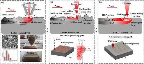
However, residual defects such as waves and bulges persisted on the samples, further affecting the surface roughness. To address these concerns and enhance the surface quality, the samples underwent additional polishing using the CW laser system as shown in (c), employing parameters of 900 W laser power, 1000 mm/s scanning speed, and 0.01 mm hatch distance. The hybrid laser polishing process involved two key steps: pulsed laser material removal and CW laser polishing. During the hybrid laser polishing, the temperature of laser scanned region is increased significantly. Therefore, the remelting and evaporation happens successively. Due to the difference of energy output mode, the pulsed laser is good at the eliminating of surface oxides and unmelted powders, while the continuous wave laser is good at the remelting of superficial layer. The specific parameters chosen for the hybrid laser polishing experiments are detailed in , ensuring precision and consistency throughout the process.
Table 2. Optimised parameters of the hybrid laser polishing.
2.2. Surface and microstructural characterisation
The hybrid laser polishing samples underwent examination for their mechanical properties and surface morphology. Subsequently, wire-cutting electrical discharge machining was employed on the samples to enable observation of the surface morphology and microstructure. Following the wire-cutting process, the samples were meticulously cleaned in acetone and ethanol through a ten-minute ultrasonic cleaning process before advancing to testing. To scrutinise the morphology, the samples were analysed utilising an FEI Quanta FEG 250 scanning electron microscope (SEM) and a Keyence VK-X200 K laser scanning confocal microscope (LSCM). The phase of the Cu Ka radiation sample was evaluated using a D8-advance-davinci X-ray diffractometer, at a grazing angle range of 20–90°, with 40 kV and 40 mA, and an interval step of 0.02°. Additionally, for a comprehensive analysis of the surface morphology and microstructure, LSCM and an SEM equipped with an electron backscatter diffraction module (EBSD) and energy dispersive spectrometer (EDS) were employed. Furthermore, a focused ion beam (FIB) was utilised for precise cutting and milling of the samples to prepare them for transmission electron microscopy (TEM) characterisation, which was conducted using the Talos F200x TEM at 200 kV.
2.3. High temperature tensile and wear measurements
The tensile test samples were produced using a CNC ultra-high pressure water cutting machine to facilitate direct testing. The schematic diagram of the tensile sample and sampling method is presented in (a). Subsequently, the samples were heated to 650°C, after which they were stabilised for 15 minutes prior to being subjected to tensile testing at a stretching rate of 0.5 mm/min using the Zwick/Roell Z100 universal material testing device at high temperatures. Stress–strain curves were generated for each of the three samples tested under the same condition for the purpose of creating representative curves. The average values from the three tests were then calculated and reported.
Figure 2. The geometry of tested specimens for (a) high-temperature tensile test, (b) high-temperature wear specimen and (c) cyclic hot corrosion.
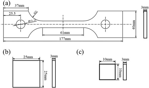
In a separate experiment, wear tests were conducted under dry sliding conditions using a GF-I multi-function material surface performance tester with a 4 mm diameter silicon nitride ceramic ball placed on the sample. The samples as shown in (b) were preheated to 650°C and stabilised for 10 minutes before applying a load of 15 N at a speed of 300 r/min for a duration of 30 minutes.
2.4. Cyclic hot corrosion measurements
Before conducting the cyclic hot corrosion test, the samples, each with dimensions of 10mm × 10mm × 3 mm as displayed in (c), underwent a sequence of preparation steps. Initially, the samples were subjected to ultrasonic cleaning in ethanol and subsequently dried in a desiccator. Following this, the mass and surface area of each sample were measured utilising an electronic balance with an accuracy of 0.01 mg and a calipre, respectively. To simulate the actual operational conditions of the components, a corrosive salt mixture composed of 87.5 wt.% Na2SO4, 5 wt.% NaCl, and 7.5 wt.% NaVO3 was formulated for the cyclic hot corrosion tests. These tests were initiated at 650°C in a heat treatment furnace and encompassed ten cycles, with each cycle comprising a 65-minute heating phase to 650°C, a 10-hour dwell time, and subsequent cooling to ambient temperature. Subsequent to each cycle, the sample underwent a thorough rinsing procedure with boiling deionised water to eliminate any residual corrosive salt on the surface, followed by heating in an oven at 80°C to ensure the removal of any residual moisture. Mass variations were monitored by examining three parallel samples after each cycle, and the resultant average value was calculated. This process was iterated ten times until completion of the cyclic high-temperature corrosion tests. Subsequently, corrosion kinetics graphs were generated for Inconel 718 alloys undergoing hybrid laser polishing to depict the relationship between corrosion duration and mass alterations. The weight change per unit area (ΔW) following each hot corrosion test cycle was quantified utilising a specific formula [Citation30].
(1)
(1) Where S is the total exposed surface area of the sample (cm2), W0 and Wt are the weights (mg) before and after hot corrosion, and ΔW is the weight change per unit area (mg/cm2).
3. Results and discussions
3.1. Surface morphology
The LDED Inconel 718 specimen exhibits a rough surface due to the multi-layer stacking forming process utilised during the LDED process, resulting in the presence of numerous unmelted powder and cladding residues on its surface. Large amounts of unmelted particles and oxides can be observed on the surface, as showcased in (a,d). This surface irregularity is further compounded by the presence of peaks and valleys, collectively contributing to an uneven surface texture. The surface roughness was measured using a laser scanning confocal microscope (LSCM) with a measuring area of 1.0 mm × 1.5 mm. Notably, the surface roughness parameter Ra was recorded at 17.34 μm, and Rz is 105.48μm. To address this surface roughness issue, the application of a pulsed laser is undertaken to rectify the surface defects of the LDED Inconel 718.
Figure 3. 3D topographic image and SEM morphology of (a,d) as-fabricated, (b,e) laser material removal and (c,f) hybrid laser polishing samples.
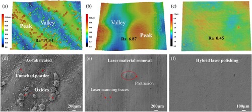
Laser material removal involves the utilisation of pulsed laser beams to either melt or vaporise the superficial layer material, consequently eliminating excess material from the substrate's surface. The effectiveness of this approach is evidenced by the removal of adhered powder particles and oxides through pulsed laser treatment, as illustrated in (b,e). Subsequently, a significant reduction in surface roughness is achieved compared to the as-fabricated sample, with the Ra value reduced to 6.87 μm, the Rz value reduced to 58.26μm. However, it should be noted that the removal of material close to the surface and the inability to further melt the raised peaks necessitate the application of higher energy CW lasers to induce additional material melting, thereby facilitating the smoothing of peaks and filling of valleys via the effects of gravity and surface tension. The surface morphology resulting from hybrid laser polishing is depicted in (c,f), demonstrating a notable reduction in roughness of approximately 97.40%, with the Ra value achieving 0.45μm, the Rz value reduced to 3.76μm.
3.2. Microstructural evolution
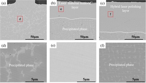
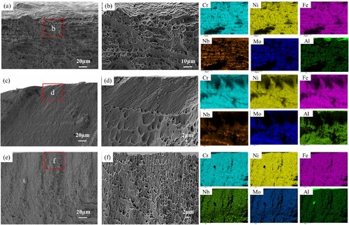
SEM and EDS were utilised to examine the cross-section of the as-fabricated, laser material removal, and hybrid laser polishing samples to investigate the impact of the hybrid laser polishing technique on the microstructure of Inconel 718, as depicted in . The initial observation revealed a dendritic microstructure with substantial size and a specific orientation within the as-fabricated sample in (a,b). The surface cross-section microstructure was characterised by dendrites and equiaxed grains, with a relatively fine grain size, attributed to the slow rate of internal heat transfer resulting in grain growth following the direction of rapid heat transfer. Furthermore, the extension of the superficial layer enhanced the heat dissipation area, inducing alterations in grain morphology and size. Upon closer examination, it was discerned that the as-fabricated sample comprised two distinct phases – gray and white. EDS analysis demonstrated a lower concentration of Ni, Fe, and Cr elements but higher levels of Nb and Mo elements in the white phase, identifying it as the precipitated Laves phase, while the gray phase predominantly consisted of the γ phase.
Figure 4. SEM micrographs and EDS mapping of the cross-section of Inconel 718 alloy subjected to different processes: (a,b) as-fabricated, (c,d) laser material removal, (e,f) hybrid laser polishing.
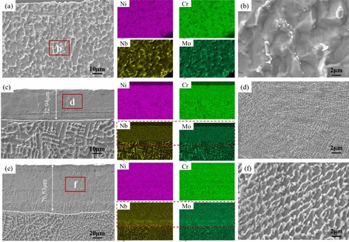
Subsequent analysis of the laser material removal sample, as displayed in (c), showcased a remelt layer approximately 32 μm thick, characterised by columnar and equiaxed crystals in the internal microstructure. Notably, no conspicuous precipitated phase was present within the remelt layer, which exhibited a more uniform element distribution compared to the as-fabricated sample, as illustrated in (d). This uniformity was attributed to the accelerated solidification rate of the liquid metal surface during laser material reduction, impeding the diffusion of Nb and Mo elements. The microstructure of the hybrid laser polished sample, as shown in (e), exhibited an increased remelted layer thickness of about 76 μm. Subsequent reprecipitation of the Laves phase and the formation of fine precipitates, resulting in a honeycomb-like skeleton breaking up the matrix into tiny blocks, were observed, as depicted in (f). Furthermore, an examination of the element distribution within the remelted layer highlighted the uneven dispersion of Nb and Mo elements at the remelted layer-substrate interface, contrasting with the even distribution of elements such as Ni and Cr.
The cross-sectional microstructures of as-fabricated, laser material removal, and hybrid laser polishing samples were observed in backscattering mode, as displayed in . In the as-fabricated sample, a significant amount of white precipitates was identified, primarily consisting of flaky Laves phase and granular fine carbides. (a,d) illustrate that the white precipitated phase exhibits a large and uneven distribution. Interestingly, on the surface of the LDED Inconel 718, the size of the white precipitated phase is small and progressively increases towards the interior. During the laser material removal process (depicted in (b,e)), the high heat input and rapid solidification time lead to the dissolution of the white precipitated phase within the remelted layer. Subsequently, the dissolved Laves phase and carbides are re-precipitated due to the large molten pool and elevated temperatures generated by hybrid laser polishing. However, compared to the as-fabricated sample, the size of the precipitated phase in the hybrid laser polishing sample is noticeably reduced, and its distribution is more uniform as shown in (c,f). Quantitative analysis reveals that the as-fabricated sample comprises 8.23% white precipitated phase, whereas the hybrid laser polishing sample contains 1.30%.
Figure 5. Back-scattering electron images of Inconel 718 alloy subjected to different processes: (a,b) as-fabricated, (c,d) laser material removal, (e,f) hybrid laser polishing.
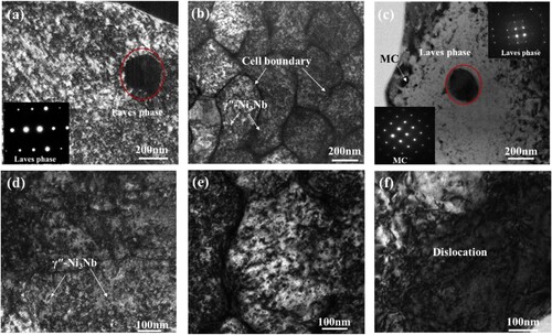
Prior to and following hybrid laser polishing, TEM observations and analysis were conducted on the samples to confirm the precipitated phase, as illustrated in . The results reveal that the coarse Laves phase and the fine-grained carbides of the LDED sample coexist and integrate with the matrix, forming a eutectic structure ((a)). The SEM and EDS element distribution analysis identifies Cr2Nb as the Laves phase and (Ti, Nb)C as the MC carbide. Moreover, fine precipitated phases are observed in the grains near the Laves phase. Examination of (d) indicates that the LDED Inconel 718 samples exhibit high-density precipitated phases, specifically γ′′-Ni3Nb phases [Citation31]. Pulsed laser reduction is found to enhance the formation of a cellular structure, as evident from the surface layer of the laser reduction sample depicted in (b). The rapid solidification of liquid metal during the laser material removal process leads to the precipitation of the γ′′-Ni3Nb phase inside the cell structure, while the secondary phase forms the cell structure shell. Further magnification of the cell structure reveals numerous layered structures surrounding it ((e)), which are a result of the fast melt solidification rate preventing the cell structure from shrinking or deforming during solidification, thereby inducing the formation of substructures to balance the internal forces caused by rapid solidification. Consequently, a layered structure is developed. Examination of the surface layer of the hybrid laser polished sample shows a reduction in the blocky Laves phase and some granular carbides ((c)), with observations revealing high-density dislocation networks around the precipitated phase, as detailed in (f).
Figure 6. Bright-field TEM micrograph of Inconel 718 alloy subjected to different processes: (a,b) as-fabricated, (c,d) laser material removal, (e,f) hybrid laser polishing.
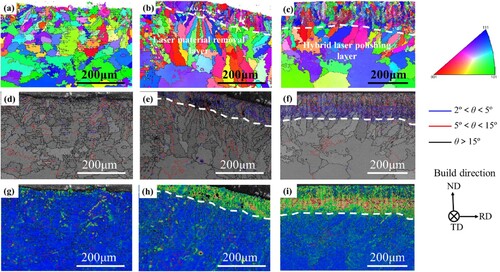
The as-fabricated, laser material removal, and laser hybrid polishing samples were analysed using EBSD to investigate the change in grain orientation during the hybrid laser polishing process. The analysis included characterisation and examination of grain orientation, grain boundary distribution, and precipitated phase distribution, as shown in . In (a), the microstructure of LDED Inconel 718 samples displays uneven distribution, with fine columnar dendrites on the surface due to faster heat dissipation, resulting in coarse grains in the interior. Furthermore, (d,g) reveal that the LDED Inconel 718 sample exhibits more uniform grain orientation with smaller small-angle grain boundaries. The grain change diagram in (b) for the laser material removal sample shows stratification, with ultrafine grains growing perpendicularly to the surface in the outermost layer, while the heat-affected zone displays larger grain sizes. In (e,h), an increase in small-angle grain boundary and noticeable change in grain orientation in the remelt zone are observed. (c) illustrates the surface grain orientation of the hybrid laser polished sample, with fine columnar crystals perpendicular to the surface dominating the remelted layer created during laser polishing. The grain size is larger compared to the laser material removal sample, and the heat-affected zone also shows increased grain sizes due to the high energy input and slow heat dissipation during laser polishing. Notably, the difference in grain orientation between the remelted layer and the matrix post laser polishing is more pronounced, with a significant enlargement in small-angle grain boundaries depicted in (f,i), aligning with the observations of the grain orientation difference and angular grain boundary region distribution.
Figure 7. EBSD crystallographic orientation map of (a) As-fabricated, (b) laser material removal and (c) hybrid laser polishing samples; Low angle grain boundaries distribution maps of (d) As-fabricated, (e) laser material removal and (f) hybrid laser polishing samples; Maps of orientation deviation angle (g) As-fabricated, (h) laser material removal and (i) hybrid laser polishing samples.
3.3. High-temperature tensile property
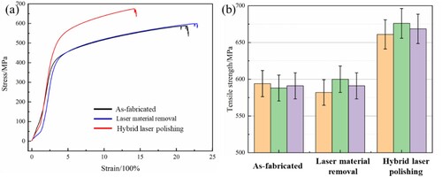
We tested the high-temperature tensile strength of hybrid laser polished Inconel 718 at 650°C to simulate real working conditions. The as-fabricated sample exhibited a yield strength of 478 ± 11 MPa, ultimate tensile strength of 588 ± 5 MPa, and an elongation rate of 21.66%, as shown in (a). Following laser material removal, the yield strength and tensile strength increased to 502 ± 9 MPa and 600 ± 10 MPa, respectively, while there was minimal impact on elongation. Subsequently, after hybrid laser polishing, the yield strength and tensile strength further rose to 664 ± 10 MPa and 676 ± 8 MPa, yet the elongation decreased to 14.51%. The hybrid laser polished Inconel 718 sample witnessed a 33.01% reduction in elongation and a 14.97% increase in tensile strength. To ensure accuracy, each sample group underwent multiple tests for the data points in (b).
Figure 8. (a) Hot tensile curves of the LDED Inconel 718 specimens before and after the hybrid laser, (b) Triple tensile strength of as-fabricated, laser material removal and hybrid laser polishing samples.
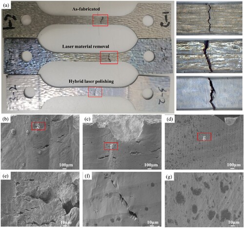
Following high-temperature tensile testing, the macroscopic morphology of the as-fabricated sample, laser material removal samples, and hybrid laser polishing samples is shown in . The standard section in (a) exhibits fractures resulting from high-temperature tensile stress. To evaluate the impact of the hybrid laser polishing process on the high-temperature tensile properties of Inconel 718, the fracture surface morphology of the tensile sample was examined and analysed. In (b,e), it is evident that the as-fabricated sample displays numerous cracks near its fracture, attributed to the presence of corresponding oxides near the crack source that facilitate crack formation. This can be seen in (c,f), where a few tiny cracks and black alumina spots are observed on the laser material removal specimen's fracture, indicating localised cracking. Moreover, (d,g) illustrate that the hybrid laser polishing sample exhibits larger black alumina spots compared to the laser material removal sample. Notably, no cracks are found near the fracture following hybrid laser polishing. Although some tiny cracks are visible on the black spots, they do not extend to the substrate, highlighting the effectiveness of the hybrid laser polishing process in reducing crack propagation.
Figure 9. (a) Tensile failure sample morphology at high temperatures; Surface morphology near the tensile fracture (b,e) as-fabricated, (c,f) laser material removal and (d,g) hybrid laser polishing samples.
The surface morphology and elemental distribution of hybrid laser polishing Inconel 718 specimens subjected to high-temperature tensile fracture are shown in . The as-fabricated sample, as depicted in (a,b), exhibits a rough fracture surface characterised by numerous dimples of varying sizes that are unevenly distributed. This rough surface indicates the good high-temperature ductility of the as-fabricated sample. However, due to the precipitation of coarser and unevenly distributed Laves along the grain boundary, the elemental distribution on the fracture surface is also uneven. The presence of a specific delamination thickness on the fracture surface results from the layer of remelted material present in a specific thickness due to laser material removal and hybrid laser polishing. Specifically, the laser material removal specimen displays a quasi-cleavage morphology on the surface, tear dimples on the inside, and a relatively smooth fracture surface ((c,d)). In contrast, the fracture surface of the hybrid laser polishing sample exhibits a surface similar to a typical tear dimple with small dimple sizes, mirroring the internal tear dimple morphology ((e,f)). Consequently, the hybrid laser polishing sample is characterised by low plasticity.
Figure 10. The high temperature tensile fracture surfaces and EDS mapping profiles of Inconel 718 samples: (a,b) as-fabricated, (c,d) laser material removal and (e,f) hybrid laser polishing.
3.4. High-temperature tribological performance
Friction and wear tests were performed at 650°C on the Inconel 718 samples to analyse the impact of hybrid laser polishing on the high-temperature wear resistance of the sample surface, comparing it with the as-fabricated and laser material removal samples. (a) illustrates the coefficient of friction of the samples. Initially, the coefficient of friction of the as-fabricated sample rapidly increased to approximately 0.8, displaying significant fluctuations within the first five minutes before stabilising at around 0.6. In contrast, the laser material removal sample exhibited a rapid rise in friction coefficient to about 1.2 at the onset of wear, followed by a sharp decline to 0.5 after two minutes, and then a gradual increase to approximately 0.6. The friction coefficient behaviour of the hybrid laser-polished sample mirrored that of the laser material removal sample, with a quick increase to 0.6 in the first two minutes, a sharp decrease to 0.2, and a subsequent gradual rise to 0.3. Notably, as the surface roughness increased, the friction coefficient of the LDED Inconel 718 samples also increased. Conversely, the friction coefficient of the hybrid laser-polished specimen was the lowest among the samples tested, showcasing its potential for enhanced wear resistance.
Figure 11. (a) The coefficient of friction of the samples before and after laser polishing at 650°C, (b) cross section profile of wear tracks of the as-fabricated, laser material removal and hybrid laser polishing (Inset image showing the wear rate of the samples before and after laser polishing at 650°C).
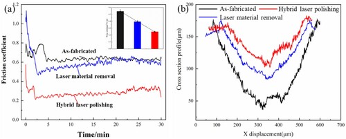
The wear traces of the as-fabricated, laser material removal, and hybrid laser polished Inconel 718 are illustrated in (b), depicting the cross-section profile. These wear scars exhibit depths of 125.62 μm, 97.45 μm, and 67.39 μm, respectively. The comparison indicates that the wear traces on the hybrid laser polished surfaces are smaller than those on the as-fabricated surface. To calculate the wear rate of the samples, the formula W=ΔV/(L × D) is utilised, where L represents the applied load, D denotes the sliding distance, and ΔV is the volume of the wear traces [Citation32]. The analysis of wear rates, as demonstrated in (a), shows that the wear rates of Inconel 718 following laser material removal and hybrid laser polishing are 0.394 and 0.247, respectively, both lower than the as-fabricated wear rates of 0.544. Surface roughness is a critical factor influencing wear resistance of materials. Decreasing surface roughness leads to a reduction in both wear rate and coefficient of friction. The hybrid laser polished samples exhibit a remelted layer with a depth of approximately 76.83 μm, containing significant precipitated phases and a specific grain fineness. Consequently, the wear resistance of the hybrid polished samples is notably improved compared to the as-fabricated sample.
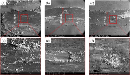
A detailed examination of the high-temperature wear mechanism of the hybrid laser polishing samples was conducted by observing and analysing the wear track characteristics at 650°C. The worn-out surface morphology of the three samples at elevated temperatures is depicted in . The wear track width of the as-fabricated sample is 1121 μm, whereas it decreases to 1086 μm for the laser material removal sample and further reduces to 987 μm after hybrid laser polishing as shown in (a–c). This reduction can be attributed to the increased contact area between the sample and the grinding ball under the same wear load conditions, despite the relatively low surface microhardness of the as-fabricated and laser material removal samples. The surface of the wear scar of the as-fabricated sample appears rough with evident surface wear, displaying numerous abrasive grains and lamellar structures characteristic of abrasive wear morphology ((d)). In contrast, the wear scar of the laser material removal sample shows signs of abrasive wear and adhesive wear, evident from the presence of defects such as pitting and chipping damage ((e)). Additionally, after laser material removal, minimal wear debris residues are found on the surface of the wear scar, indicating prominent spalling and the development of microcuts on the surface. The hybrid laser polished sample displays an oxide layer on its surface, along with furrows and spalling as shown in (f). This suggests a wear mechanism consisting of a combination of adhesive and oxidative wear, possibly attributed to the uniform distribution of elements like Nb, Cr, and Mo on the Inconel 718 surface post hybrid laser polishing. This uniform distribution facilitates the formation of an oxide layer during the wearing process, resulting in a denser oxide layer on the wear scar surface, significantly enhancing Inconel 718's wear resistance.
Figure 12. SEM images of worn-out surfaces of (a,b) as-fabricated, (c,d) laser material removal and (e,f) hybrid laser polishing samples at 650°C.
3.5. Cyclic hot corrosion performance
After ten cycles of exposure to the salt mixture at 650°C, the weight fluctuations of the hybrid laser-polished Inconel 718 alloy samples are illustrated in . It depicts that the mass loss of the three samples initially increases, then decreases, and subsequently increases as the test duration progresses. This pattern is primarily attributable to the rapid reaction between the corrosive salt mixture and the surface material during the early corrosion stages, leading to the generation of a substantial amount of corrosion products. However, the rate of weight loss accelerates due to the inherent instability of the corrosion products, causing them to detach easily from the surface. Over time, as the process of hot corrosion continues, the surface material of the samples interacts with various elements, such as mixed salts and oxygen, culminating in the development of a corroded layer. Consequently, the rate of mass loss gradually diminishes. The velocity of mass loss regains momentum as soon as the corrosive medium penetrates the corroded layer.
Figure 13. (a) Weight changes of Inconel 718 specimens due to hot corrosion at 650°C as a function of time, (b) Photographical surface of the Inconel 718 after hot corroded at 650°C for 100 h.
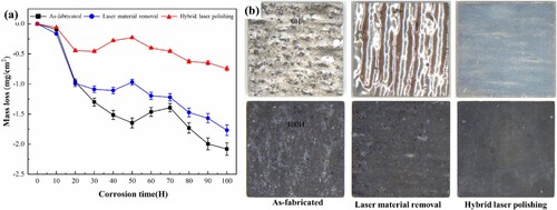
(a) indicates that the as-fabricated sample initially exhibits the fastest corrosion mass loss rate, with a corrosion layer forming after 50 hours of exposure to corrosion. In contrast, both the laser material removal and hybrid laser polishing processes lead to a significant reduction in the early corrosion mass loss rate, resulting in the formation of a corrosion layer after only 30 hours of corrosion. Notably, the weight loss due to hot corrosion in the as-fabricated sample surpasses that of the hybrid laser-polished Inconel 718 samples. Specifically, the weight loss values for the as-fabricated, laser material removal, and laser polishing of Inconel 718 alloy samples are recorded as 2.08 mg/cm2, 1.77 mg/cm2, and 0.74 mg/cm2, respectively. Consequently, the hybrid laser polishing treatment demonstrates superior resistance to hot corrosion compared to the other methods.
Hybrid laser polishing of Inconel 718 samples hot corroded at 650°C for 100 hours is shown in (b), revealing a black oxide layer composed mainly of NiO and other oxides on the outer layer of the three samples [Citation33]. A comparison with the uncorroded sample highlights a noticeable oxide spalling zone on the surface of the as-fabricated hot corrosion sample, attributed mainly to defects like unmelted particles. Such protruding portions are more susceptible to hot corrosion, potentially causing extensive damage to the surface. The corrosion quality of the as-fabricated material is most severely affected during high-temperature corrosion due to this phenomenon. Laser material removal significantly reduces the occurrence of hot corrosion as it eliminates unmelted particles on the surface. However, even after laser material removal, the surface may still exhibit bumps and indentations, thereby increasing the surface area exposed to the corrosive medium, leading to spalling and pitting. In contrast, the hybrid laser polishing sample displays minimal spalling and pitting on the surface due to the substantial reduction in roughness, which limits the reaction area between Inconel 718 and the salt mixture. Therefore, it is evident that hybrid laser polishing enhances the hot corrosion resistance of Inconel 718.
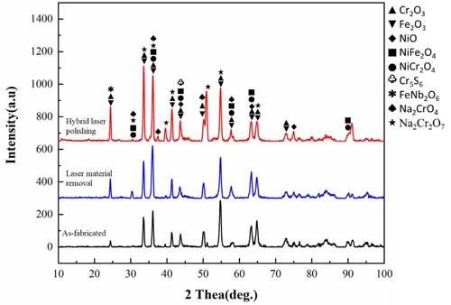
The XRD diffraction patterns of the as-fabricated, laser material removal, and hybrid laser polishing Inconel 718 alloy specimens after being hot-corroded at 650°C for 100 hours are illustrated in . Among these samples, the diffraction peaks of the hot corrosion products, primarily Cr2O3, Fe2O3, NiO, NiCr2O4, NiFe2O4, Cr5S6, FeNb2O6, Na2CrO4, and Na2Cr2O7, exhibit similarities. It is notable that the hot corrosion products on the surface of Inconel 718 remain unaffected by hybrid laser polishing, as the various laser manufacturing techniques primarily lead to a redistribution of elements in the Inconel 718 alloy rather than altering the proportion of elements [Citation34]. Kang pointed out that during high-temperature corrosion, the surface of Inconel 718 parts forms oxides based on Cr and Ni [Citation35]. Initially, when corrosion begins, the Cr element reacts with components in the mixed salt and oxygen in the air to produce Cr-based oxides, with the Cr element primarily forming Cr2O3 by reacting with O2. The thickness and compactness of Cr2O3 confer a certain level of resistance to oxidation on the surface, serving as a barrier against further high-temperature corrosion [Citation36]. However, the Cr2O3 layer eventually corrodes and deteriorates as corrosion progresses. Concurrently, the Ni element on the surface reacts with O2 to generate NiO, which further transforms into spinels like NiCr2O4. The as-fabricated sample demonstrates an uneven distribution of elements such as Ni and Cr, leading to a less compact Cr2O3 layer on the surface during the hot corrosion process, thereby increasing the susceptibility to corrosion. In contrast, the distribution of elements like Ni, Cr, and Fe becomes more uniform in the remelting layer as a result of the laser material removal and hybrid laser polishing processes. Consequently, the high-density Cr2O3 layer formed during the hot corrosion process enhances the high-temperature hot corrosion resistance of the Inconel 718 superalloy, showcasing the benefits of these processes.
Figure 14. XRD diffraction patterns of Inconel 718 specimens hot-corroded at 650°C for 100 h.
displays the surface morphologies and elemental distribution of Inconel 718 specimens following exposure to the mixed salt at 650°C for 100 hours. It is observed that all surfaces exhibit similar oxide morphology, characterised by a notable presence of spinels and granular oxidation products. Notably, significant granular detachment is evident on the as-fabricated sample ((a,b)), while subsequent processes of laser material removal and hybrid laser polishing result in a minor lamellar detachment on the surface of the sample ((c,d) and (e,f)). The as-fabricated surface exhibits the highest spinel content, whereas the surface after hybrid laser polishing shows the lowest spinel content. Analysis via EDS reveals that the elements O, Na, Ni, V, Fe, and Cr predominantly constitute these spinels, as detailed in . Building upon the preceding XRD phase analysis, the findings suggest the potential presence of oxides such as Cr2O3, NiCr2O4, NiO, and Fe2O3 formed on the surface due to high-temperature corrosion.
Figure 15. Surface morphology of hot corroded Inconel 718 specimens at 650°C for 100 h: (a,b) as-fabricated, (c,d) laser material removal and (e,f) hybrid laser polishing samples.
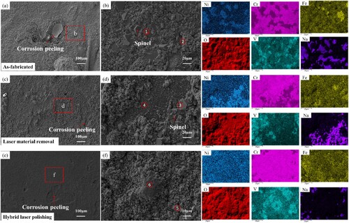
Table 3. The EDS analysis on the surface oxide scales of hot corroded samples (wt.%).
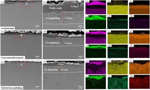
The cross-sectional microstructure and EDS mapping profiles of as-fabricated, laser material removal, and hybrid laser polishing samples after 100 hours of corrosion in a corrosive mixed salt medium at 650°C were observed and analysed to understand the reaction process between the surface material and the corrosive medium during the hot corrosion process (). The diagram clearly shows that all samples develop a visible oxide layer on their surface after high-temperature hot corrosion. Specifically, the surface oxide layer of the as-fabricated sample exhibits a substantial thickness of up to 29.48μm ((a,b)). Subsequent laser material removal decreases the surface oxide layer thickness to 14.68 μm ((c,d)), and hybrid laser polishing further reduces it to 8.86 μm ((e,f)). The oxide layer identified on the sample surfaces predominantly consists of Cr, Fe, Al, and O elements, with lesser quantities of Ni, Nb, and Mo elements. Upon the combination of Cr and Fe with O, oxides such as Cr2O3 and Fe2O3 are formed. Beneath the oxide layer lies a sulfide layer, characterised by granular and striped sulfides. Initially, the as-fabricated sulfide layer measures 32.83 μm, with subsequent reduction to 22.36 μm after laser material removal and finally reaching a minimum thickness of 20.79 μm following hybrid laser polishing. The primary constituents of the sulfide layer include S, Ni, Fe, and Mo while displaying a noticeable consumption of Cr. Observations suggest that during the high-temperature hot corrosion process, Cr diffuses from the interior to the surface layer where it reacts with O from the corrosive medium and air. Furthermore, the sulfide layer exhibits higher concentrations of Ni and Fe compared to the interior, indicating the inward diffusion of these elements from the sample interior and subsequent reaction with sulfur. Thus, it is evident that the hybrid laser polishing process enhances the hot corrosion resistance of Inconel 718 by reducing surface oxidation and sulfidation.
Figure 16. EDS mapping profiles in cross-section of hot corroded Inconel 718 alloy: (a–b) as-fabricated, (c–d) laser material removal samples, (e–f) hybrid laser polishing samples.
In conclusion, the distribution and content of the Cr element play a crucial role in influencing high-temperature hot corrosion. Specifically, during high-temperature hot corrosion, Cr ions are transported to the surface through the grain boundary and promptly react with oxygen and the corrosive medium to create an oxide film. The presence of Cr ions within the oxide film inhibits the migration of Fe ions from the film, thus enhancing the resistance to high-temperature hot corrosion. Although the hybrid laser polishing process does not alter the distribution and content of the Cr element, it does affect the microstructure of the surface layer by promoting the formation of small-angle grain boundaries. Consequently, this structural change reduces the outward diffusion rates of Cr, Ni, and Fe, thereby improving the sample surface's resilience to high temperatures and hot corrosion. Moreover, the post-polishing surface roughness is significantly diminished, reducing the adhesion points for mixed salt corrosion medium, ultimately bolstering the hot corrosion resistance of the Inconel 718 alloy.
4. Conclusions
The utilisation of hybrid laser polishing in the fabrication process of Inconel 718 created by LDED aimed to enhance the surface quality and high-temperature behaviour of the alloy. A comprehensive analysis of microstructure evolution was conducted on the hybrid laser-polished LDED Inconel 718. Concurrently, the effects of hybrid laser polishing on high-temperature wear, corrosion performance, and tensile strength were thoroughly examined. Some conclusions can be obtained as bellow.
Hybrid laser polishing post-treatment demonstrated a significant enhancement in surface quality. The surface roughness of the polished sample was notably reduced by approximately 97.4%, with Ra and diminishing by 0.45 μm and 3.76μm respectively.
The application of hybrid laser polishing resulted in the formation of a remelted layer of 76 μm on the superficial layer of LDED Inconel 718. This process led to a uniform redistribution of internal elements, promoted the precipitation of phase reduction in size. Thereby contributing to a substantial enhancement in high-temperature performance.
The high-temperature tensile strength, wear resistance, and corrosion resistance of the LDED 718 samples showed improvements following the implementation of hybrid laser polishing post-treatment. Notably, the high-temperature tensile strength exhibited a remarkable increase of 14.97%. The wear rate of LDED Inconel 718 at 650 °C decreased to 0.247. Moreover, the weight loss related to hot corrosion resistance decreased from 2.08 mg/cm2 to 0.74 mg/cm2.
Disclosure statement
No potential conflict of interest was reported by the author(s).
Data availability statement
The data that support the findings of this study are avail-able from the corresponding author upon reasonable request.
Additional information
Funding
References
- Liu F, Gao J, Liu F, et al. The anisotropic wear and friction property of Inconel 718 superalloy fabricated by laser directed energy deposition. Tribol Int. 2024;188:108835. doi: 10.1016/j.triboint.2023.108835
- Du B, Hu Z, Sheng L, et al. Tensile, creep behavior and microstructure evolution of an as-cast Ni-based K417G polycrystalline superalloy. J Mater Sci Technol. 2018;34(10):1805–1816. doi: 10.1016/j.jmst.2018.02.007
- Ajmal KM, Yi R, Zhan Z, et al. A novel finishing approach for 3D printed inconel 718 by utilizing isotropic electrochemical etching. J Mater Process Technol. 2022;299:117356. doi: 10.1016/j.jmatprotec.2021.117356
- Zhang LN, Ojo OA. Corrosion behavior of wire arc additive manufactured Inconel 718 superalloy. J Alloys Compd. 2020;829:154455. doi: 10.1016/j.jallcom.2020.154455
- Mondragon-Rodriguez G, Torres-Padilla N, Camacho N, et al. Surface modification and tribological behavior of plasma nitrided Inconel 718 manufactured via direct melting laser sintering method. Surf Coat Technol. 2020;387:125526. doi: 10.1016/j.surfcoat.2020.125526
- Li H, Feng S, Li J, et al. Effect of heat treatment on the δ phase distribution and corrosion resistance of selective laser melting manufactured Inconel 718 superalloy. Mater Corros. 2018;69:1810159. doi: 10.1002/maco.201810159
- Park S, Liu P, Yi K, et al. Mechanical properties estimation of additively manufactured metal components using femtosecond laser ultrasonics and laser polishing. Int J Mach Tools Manuf. 2021;166:103745. doi: 10.1016/j.ijmachtools.2021.103745
- Yu Z, Zheng Y, Chen J, et al. Effect of laser remelting processing on microstructure and mechanical properties of 17-4 PH stainless steel during laser direct metal deposition. J Mater Process Technol. 2020;284:116738. doi: 10.1016/j.jmatprotec.2020.116738
- Sun Y, Jin L, Gong Y, et al. Experimental evaluation of surface generation and force time-varying characteristics of curvilinear grooved micro end mills fabricated by EDM. J Manuf Process. 2022;73:799–814. doi: 10.1016/j.jmapro.2021.11.049
- Kumar S, Satapathy B, Pradhan D, et al. Effect of surface modification on the hot corrosion resistance of Inconel 718 at 700°C. Mater Res Express. 2019;6:086549. doi: 10.1088/2053-1591/ab1dc7
- Yao C, Wu D, Ma L, et al. Surface integrity evolution and fatigue evaluation after milling mode, shot peening and polishing mode for TB6 titanium alloy. Appl Surf Sci. 2016;387:1257–1264. doi: 10.1016/j.apsusc.2016.06.162
- Beaucamp AT, Namba Y, Charlton P, et al. Finishing of additively manufactured titanium alloy by shape adaptive grinding (SAG). Surf Topogr Metrol Prop. 2015;3:024001. doi: 10.1088/2051-672X/3/2/024001
- Idaszek J, Buhagiar J, Szl K, et al. The influence of chemical polishing of titanium scaff olds on their mechanical strength and in-vitro cell response. Mat Sci Eng C. 2019;95:428–439. doi: 10.1016/j.msec.2018.04.019
- Qin LY, Men JH, Zhang LS, et al. Microstructure homogenizations of Ti-6Al-4 V alloy manufactured by hybrid selective laser melting and laser deposition manufacturing. Mater Sci Eng A. 2019;759:404–414. doi: 10.1016/j.msea.2019.05.049
- Dong G, Marleau-Finley J, Zhao YF. Investigation of electrochemical post-processing procedure for Ti-6Al-4 V lattice structure manufactured by direct metal laser sintering (DMLS). Int J Adv Manuf Technol. 2019;104(9-12):3401–3417. doi: 10.1007/s00170-019-03996-5
- Nesli S, Yilmaz O. Surface characteristics of laser polished Ti-6Al-4 V parts produced by electron beam melting additive manufacturing process. Int J Adv Manuf Technol. 2021;114(1-2):271–289. doi: 10.1007/s00170-021-06861-6
- Liu Z, Wang C, Mi G, et al. Surface morphological evolution and microhardness change of Cr12MoV steel by pulsed laser polishing. Opt Laser Technol. 2024;171:110419. doi: 10.1016/j.optlastec.2023.110419
- Mushtaq R, Wang Y, Khan A, et al. A post-processing laser polishing method to improve process performance of 3D printed new Industrial Nylon-6 polymer. J Manuf Process. 2023;101:546–560. doi: 10.1016/j.jmapro.2023.06.019
- Abdullah M, Evgueni V, Remus O. Experimental analysis of applicability of a picosecond laser for micro-polishing of micro-milled Inconel 718 superalloy. Int J Adv Manuf Technol. 2014;70(9-12):1963–1978. doi: 10.1007/s00170-013-5408-9
- Fang Z, Lu L, Chen L, et al. Laser polishing of additive manufactured superalloy. Procedia CIRP. 2018;71:150–154. doi: 10.1016/j.procir.2018.05.005
- Hou JT, Xu H, Li H, et al. In-situ laser polishing additive manufactured AlSi10Mg effect of laser polishing strategy on surface morphology, roughness and microhardness. Materials (Basel). 2021;14(2):393. doi: 10.3390/ma14020393
- Dadbakhsh S, Hao L, Kong CY. Surface finish improvement of LMD samples using laser polishing. Virtual Phys Prototyp. 2010;5(4):215–221. doi: 10.1080/17452759.2010.528180
- Marimuthu S, Triantaphyllou A, Antar M, et al. Laser polishing of selective laser melted components. Int J Mach Tools Manuf. 2015;95:97–104. doi: 10.1016/j.ijmachtools.2015.05.002
- Li J, Wu H, Liu H, et al. Surface and property characterization of selective laser-melted Ti-6Al-4 V alloy after laser polishing. Int J Adv Manuf Technol. 2023;128(1-2):703–714. doi: 10.1007/s00170-023-11880-6
- Wang Y, Li Y, Guan Y. Surface modification and mechanical properties of laser powder bed fusion Inconel 718 after magnetic-assisted laser polishing. Opt Laser Technol. 2023;162:109291. doi: 10.1016/j.optlastec.2023.109291
- Kang D, Zou P, Wu H, et al. Research on ultrasonic vibration-assisted laser polishing of the 304 stainless steels. J Manuf Process. 2021;62:403–417. doi: 10.1016/j.jmapro.2020.12.009
- Metelkova J, Vanmunster L, Haitjema H, et al. Hybrid dual laser processing for improved quality of inclined up-facing surfaces in laser powder bed fusion of metals. J Mater Process Technol. 2021;298:117263. doi: 10.1016/j.jmatprotec.2021.117263
- Liu Y, Ouyang W, Wu H, et al. Improving surface quality and superficial microstructure of LDED Inconel 718 superalloy processed by hybrid laser polishing. J Mater Process Technol. 2021;300:117428. doi: 10.1016/j.jmatprotec.2021.117428
- Liu Y, Sun S, Wang J, et al. Tribological behaviors of LDED Inconel 718 samples polished with a hybrid laser polishing technique. J Mat Res Technol. 2023;25:633–646. doi: 10.1016/j.jmrt.2023.05.230
- Zhang J, Zhang Q, Zhuang Y, et al. Microstructures and cyclic hot corrosion behavior of laser deposited Inconel 718 alloy under different heat treatment conditions. Opt Laser Technol. 2021;135:106659. doi: 10.1016/j.optlastec.2020.106659
- Sano K, Oono N, Ukai S, et al. γ″-Ni3Nb precipitate in Fe-Ni base alloy. J Nucl Mater. 2013;442(1-3):389–393. doi: 10.1016/j.jnucmat.2013.07.037
- Xu Z, Ouyang W, Liu Y, et al. Effects of laser polishing on surface morphology and mechanical properties of additive manufactured TiAl components. J Manuf Process. 2021;65:51–59. doi: 10.1016/j.jmapro.2021.03.014
- Gong G, Wang Z, Du X, et al. Comparative study on mechanical properties and high temperature oxidation behaviour of Hastelloy X and Inconel 718 fabricated by laser directed energy deposition. J Mat Res Technol. 2024;28:2624–2635. doi: 10.1016/j.jmrt.2023.12.199
- Mannava V, Rao AS, Paulose N, et al. Hot corrosion studies on Ni-base superalloy at 650 ◦C under marine-like environment conditions using three salt mixture (Na2SO4 + NaCl + NaVO3). Corros Sci. 2016;105:109–119. doi: 10.1016/j.corsci.2016.01.008
- Kang YJ, Yang S, Kim YK, et al. Effect of post-treatment on the microstructure and high-temperature oxidation behaviour of additively manufactured inconel 718 alloy. Corros Sci. 2019;158:108082. doi: 10.1016/j.corsci.2019.06.030
- Liu FJ, Zhang M, Dong J, et al. High-temperature oxidation of FGH96 P/M superalloy. Acta Metall Sinica. 2007;20:102–110. doi: 10.1016/S1006-7191(07)60014-3