
 ?Mathematical formulae have been encoded as MathML and are displayed in this HTML version using MathJax in order to improve their display. Uncheck the box to turn MathJax off. This feature requires Javascript. Click on a formula to zoom.
ABSTRACT
Subjected to repeated heating and cooling, laser directed energy deposited (LDED) parts always possess considerable residual stress, which severely limits their industrial applications. In this work, cyclic deep cryogenic treatment (CDCT) was performed to finely tune the residual stress and microstructure of LDED-fabricated CrCoNi medium-entropy alloy (MEA). With increasing number of CDCT cycles, crystalline defects within the sample became denser due to the repeated visco-plastic deformation. The compressive residual stress (CRS) of the sample was estimated to be 361.9 ± 16.8 MPa after 30 cycles of CDCT, 64.2% higher than that in the as-built condition. Due to the existence of dense crystalline defects and high CRS, the corrosion and wear rates of CDCT-treated CrCoNi MEA were significantly decreased compared with the as-built condition. This work demonstrated CDCT as an effective means for regulating the residual stress, microstructure, and surface performance of LDED-fabricated MEA.
1. Introduction
Laser directed energy deposition (LDED) is a relatively new technique for fabricating metallic components with complicated geometries, using digitally controlled track-by-track and layer-by-layer deposition [Citation1–3]. However, the repeated solidification and melting during LDED generate large and non-uniformly distributed residual stresses within the formed parts, which may lead to deformation during the subsequent machining process [Citation4]. To eliminate or adjust the residual stresses within the LDED-fabricated components, heat treatment is usually carried out, resulting in the disappearance of almost all residual stress. However, for alloys without precipitation and phase transformation, such as single phase high-entropy alloys (HEAs), medium-entropy alloys (MEAs), and pure metals, their mechanical performance is usually deteriorated after heat treatment due to the microstructural recovery. Thus, additional post-treatments such as ultrasonic rolling [Citation5] and laser shock peening [Citation6–8] are needed to improve the mechanical properties of the alloy by forming a deformation layer and introducing compressive residual stress (CRS) on the surface to improve fatigue, corrosion, friction, and fracture properties [Citation9]. However, these post-treatments are limited by the geometrical shape of the parts and cannot handle parts with complex structures. Moreover, these complex processes introduce considerable time costs and are not conducive to industrial production. Therefore, it is necessary to develop better post-treatment processes for LDED-fabricated parts that can both regulate the internal residual stresses and improve the properties.
Deep cryogenic treatment (DCT) is a method for strengthening and toughening metallic materials at – 130 ∼ – 196°C. DCT was originally applied to steels to promote the transformation of residual austenite into high-strength martensite, with many advantages such as non-destructive, time-efficient, safe, and controllable [Citation10,Citation11]. Subsequent research has shown that DCT can not only regulate the residual stress inside steels, aluminum alloys [Citation12], magnesium alloys [Citation13], titanium alloys [Citation14] and other metallic materials [Citation15,Citation16], but also improve their surface hardness, impact toughness and wear resistance. Zhou et al. [Citation17] found that after DCT, the residual stress of laser-powder-bed-fusion fabricated AlSi10Mg alloy relieved up to 72.7%, but the yield stress, ultimate tensile strength, and elongation were barely affected compared with the as-built alloy, while these properties significantly dropped after heat treatment. Li et al. [Citation18] found that DCT resulted in a twofold increase in the tensile yield strength of LDED-fabricated CoCrFeMnNi HEA compared with the as-fabricated state, due to a large CRS and rich defect generation during the DCT.
CrCoNi MEA possesses excellent strength and ductility, corrosion resistance, irradiation resistance, and damage-tolerance, and is considered to be an alloy with great potential for industrial applications [Citation19,Citation20]. However, CrCoNi MEA formed using LDED also suffers from high residual stresses and requires post-treatment before application. Inspired by the abovementioned research, in the present work, cyclic deep cryogenic treatment (CDCT) is introduced to regulate the residual stress, microstructure, and properties of LDED-fabricated CrCoNi MEA. The goal of this work is to study the relationship between the number of CDCT cycles, residual stress, and microstructure of the MEA. Considering that in practice, the surface layer of the LDED-formed components is partially cut away for roughness or dimensional control, the corrosion resistance and frictional properties of cross sections of the alloy subjected to different CDCT cycles were studied. This research should provide new insight into means to elevate the application potential of LDED-formed MEAs and HEAs.
2. Materials and methods
2.1. Materials preparation and CDCT process
The CrCoNi MEA samples used in this work were fabricated by a self-developed LDED equipment, as shown in (a). The raw equimolar CrCoNi MEA powder was prepared by gas atomisation in an argon atmosphere (Beijing Yanbang New Material Technology Co., Ltd, China). (b) shows the morphology and corresponding elemental distribution of the CrCoNi MEA powder. The particle size ranges from 45 to 105 μm, with a D50 value of 72.1 μm. The substrate used for deposition was AISI 1045 steel with a dimension of 50 mm × 50 mm × 15 mm. Before the LDED process, the working surface of the substrate was ground by sandpaper and cleaned with anhydrous ethanol. The detailed parameters of the LDED process are listed in . The scanning strategy involved an S-shaped path with a rotational angle of 180° between adjacent deposited layers, as depicted in (c). (d) shows an LDED-fabricated CrCoNi sample with a dimension of ∼ 35 mm × 35 mm × 20 mm. (e) presents the schematic diagram of the CDCT process applied onto the LDED-fabricated samples. In one CDCT cycle, the as-built sample initially at room temperature was immersed in liquid nitrogen and kept for 12 h, then taken out of the liquid nitrogen and immersed in room-temperature water for another 1 h, and then immersed in liquid nitrogen again. The number of CDCT cycles was 0, 10, 20, and 30, and the corresponding samples were denoted as as-built, CDCT-10, CDCT-20, and CDCT-30, respectively.
Figure 1. LDED process and CDCT treatment of CrCoNi MEA samples: (a) LDED equipment employed in this work; (b) SEM image and corresponding EDS mappings of the gas-atomised CrCoNi MEA powders; (c) schematic diagram of the scanning strategy and sampling position for performance testing; (d) LDED-fabricated CrCoNi MEA bulk sample; (e) schematic illustration of CDCT process.
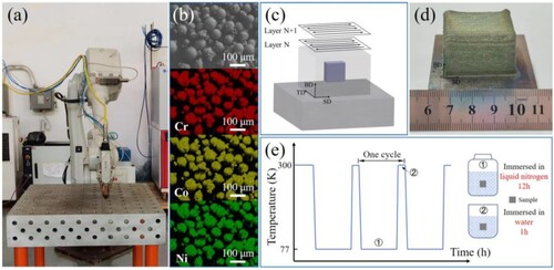
Table 1. LDED parameters employed for fabricating CrCoNi MEA samples.
2.2. Microstructure characterisation and residual stress measurement
In this work, phase analysis was performed using an X-ray diffractometer (XRD, Empyrean) equipped with a Cu-Kα radiation. The scanning was performed from 30° to 100° at rate 4 °/min. Nanoindentation (in Agilent Nano Indenter G200) was conducted with a peak load of 30 mN held for 10 s to measure the residual stress of the samples. Scanning electron microscopy (SEM) in a Zeiss Supra55 microscope equipped with an energy dispersive spectrometer (EDS) was conducted to characterise the corrosion and wear morphologies. Electron backscatter diffraction (EBSD) analysis and transmission electron microscopy (TEM, Talos F200X) were performed to examine the microstructure of the samples.
A sample used for microstructure characterisation and performance tests was electrical-discharge machined from the center of the as-built CrCoNi MEA ((c)). The plane spanned by the building direction (BD) and scanning direction (SD) of the cut sample was selected as the working surface for the XRD, SEM, EBSD and TEM characterisation, as well as the nanoindentation, corrosion and wear tests. Before each test, this surface was carefully ground and polished to mirror surface, and then ultrasonically cleaned with anhydrous ethanol. The samples used for EBSD characterisation were electropolished in a solution with alcohol: perchloric acid ratio of 9: 1 at 25 V for ∼ 50 s. The TEM samples were electrical discharge machined along the BD-SD plane of the cut sample with a thickness of ∼1 mm, and then thinned by mechanical grinding and ion milling.
2.3. Electrochemical corrosion tests
Electrochemical tests were carried out on an electrochemical work station (CHI604E, Shanghai Chenhua Co., Ltd.) using a three-electrode setup. A saturated calomel electrode (SCE) was employed as the reference electrode and a platinum foil with a size of 10 mm × 10 mm was employed as the counter electrode. The cut samples were used as the working electrode and the exposed working area was 1 cm2. All electrochemical tests were performed in 3.5 wt% NaCl solution at room temperature. Firstly, the sample was immersed in the electrolyte for 1 h to stabilise the open current potential (OCP). Then, potentiodynamic polarisation measurement was made from −0.4 V vs OCP to +1 VSCE with a scanning rate of 1 mV/s, and the test was repeated three times for each sample. Finally, electrochemical impedance spectroscopy (EIS) was performed at a frequency range of 10−2 ∼ 105 Hz and an amplitude of 5 mV. The obtained EIS data were fitted by the ZSimpWin software.
2.4. Tribological property tests
The wear properties were examined by dry sliding wear tests using a reciprocating wear machine (MFT-5000 Tribometer, Nanjing) at room temperature. A SiC ball with a diameter of 2.5 mm under a normal load of 20 N was made to slide on the sample surface at a speed of 6 mm/s, a motion frequency of 0.8 Hz and a test time of 20 min. The wear rate (W) was calculated as [Citation21,Citation22]:
(1)
(1) where V is the wear volume (mm3), S is the sliding distance (m), and F is the normal load (N).
2.5. Measurement consistency
Generally, LDED-formed parts may possess metallurgical defects such as gas pores, lack of fusion and micro-cracks, which may adversely affect the consistency of the measured properties. However, the relative density of the present as-built, CDCT-10, CDCT-20, and CDCT-30 samples was determined by image binarization method to be 99.98%, 99.93%, 99.94%, and 99.94%, respectively. These high density values ensure good consistency in the present experimental measurements.
3. Results and discussion
3.1. XRD and residual stress measurements
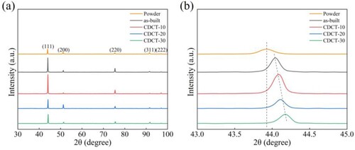
shows the XRD patterns of the CrCoNi MEA raw powder, and the as-built and CDCT-treated samples. All patterns exhibit a single fcc phase, and compared with the raw powder, the XRD peaks of the as-built and CDCT-treated samples shift rightward, indicating the existence of CRS within these samples [Citation23]. Furthermore, the (111) peaks of the CDCT-treated samples continuously shift rightward as the number of CDCT cycles increases. This phenomenon suggests that the CDCT is an effective method to increase the CRS within the as-built sample. Meanwhile, the CDCT-treated samples exhibit broadening of the (111) peak as seen in (b), which may be attributed to the formation of crystalline defects [Citation24,Citation25].
Figure 2. (a) XRD patterns of CrCoNi MEA raw powders, as-built, CDCT-10, CDCT-20, and CDCT-30; (b) enlarged view of (111) peaks in (a).
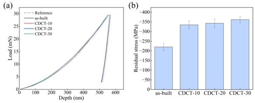
Nanoindentation tests were conducted to quantify the value of CRS within the samples, and the corresponding load-displacement curves are shown in (a). At a fixed force of 30 mN, the depth of indentation was estimated to be 566.7, 563.2, 563.0, and 562.4 nm for the as-built, CDCT-10, CDCT-20, and CDCT-30 samples, respectively. According to the literature [Citation26,Citation27], this trend demonstrates a gradual increase in CRS after CDCT. Based on the nanoindentation results, the CRS can be estimated as [Citation28]:
(2)
(2) where H is the hardness determined to be 3.713, 3.721, 3.739, and 3.742 GPa for the as-built, CDCT-10, CDCT-20, and CDCT-30 samples, respectively. α = 24.7° is the angle between the indenter and the sample surface, and h0 and h are the indentation depth without and with residual stress, respectively. The sample annealed at 600 °C for 3 h was selected as the reference assumed to be free of residual stress (0 MPa). As shown in (b), the CDCT-treated samples possess a higher CRS value compared with the as-built sample, with CDCT-30 exhibiting the maximum CRS of 361.9 ± 16.8 MPa among the four samples, about 64.2% higher than that (220.4 ± 18.3 MPa) of the as-built sample.
Figure 3. Residual stress measurements of as-built, CDCT-10, CDCT-20, and CDCT-30: (a) load-displacement curves and (b) estimated residual stresses.
3.2. Microstructure characterisation
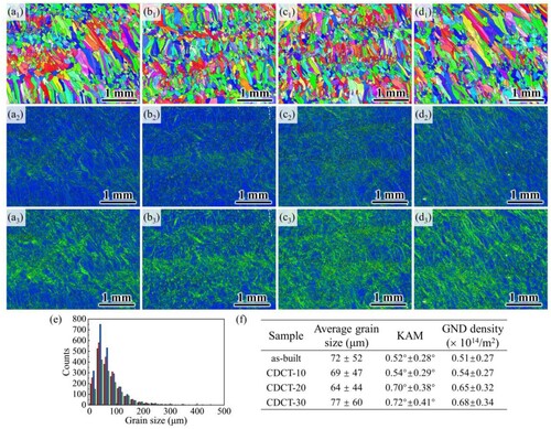
shows the EBSD results of the samples subjected to different CDCT cycles. As seen in the IPF (inverse pole figures) maps, the grain morphology remains almost unchanged before and after the CDCT. The average grain sizes were estimated to be 72 ± 52 μm, 69 ± 47 μm, 64 ± 44 μm, and 77 ± 60 μm for the as-built, CDCT-10, CDCT-20, and CDCT-30 samples, respectively ((e)), i.e. the average grain size does not varies significantly, implying that the CDCT hardly changed the grain size of the studied samples. The KAM (kernel average misorientation) maps show that the local misorientation becomes higher with increasing CDCT cycles, especially in regions with a higher percentage of smaller grains. This phenomenon may be caused by synergetic deformation in CrCoNi MEA composed of multi-sized grains during CDCT. Geometrically necessary dislocation (GND) density calculated from the KAM value also shows a similar trend as the KAM maps, as shown in (a3–d3). (f) shows the average KAM values and GND densities of the samples, both of which increase with increasing CDCT cycles. According to the above EBSD images, it can be noticed that the effect of CDCT on the grain morphology is negligible, whereas CDCT has a significant impact on microstructure. Thus, TEM characterisation was conducted to further confirm the above phenomenon.
Figure 4. IPF maps (a1-d1), KAM maps (a2-d2), and GND density maps (a3-d3) of samples: (a) as-built, (b) CDCT-10, (c) CDCT-20, and (d) CDCT-30. (e) is the distribution of grain sizes. (f) is the average grain size, and average value of KAM and GND density.
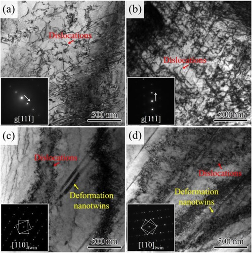
shows the TEM images of the as-built, CDCT-10, CDCT-20, and CDCT-30 samples. The as-built sample exhibits dislocations of a mild density of (1.52 ± 0.41) × 1014 m−2 ((a)) which can be attributed to the high thermal stress during the LDED process [Citation29]. After CDCT, the dislocation density increases significantly, and are determined to be (1.84 ± 0.65) × 1014 m−2, (3.26 ± 0.52) × 1014 m−2, and (4.68 ± 0.38) × 1014 m−2 for CDCT-10, CDCT-20, and CDCT-30, respectively. In addition to higher dislocation density, the samples after CDCT also contained deformation nanotwins, the density of which increases with the number of CDCT cycles ((c,d)). The results here indicate that crystalline defects including dislocations and nanotwins are continuously generated upon CDCT, which will be discussed in Section 3.5.
Figure 5. TEM images of (a) as-built, (b) CDCT-10, (c) CDCT-20, and (d) CDCT-30. The inset images in (a) and (b) are the corresponding g vector. The inset images in (c) and (d) are the corresponding SAED patterns.
3.3. Corrosion resistance
3.3.1. Potentiodynamic polarisation
(a) shows the polarisation curves of the as-built, CDCT-10, CDCT-20, and CDCT-30 samples. As seen, all the samples possess the typical passivation behaviour, while the passive potential range varies with respect to the number of CDCT cycles. In comparison, the CDCT-30 showed a narrower passive potential range than the others, suggesting a limited capability of withstanding corrosion. However, the passive current density of CDCT-30 is lowest among the four samples, followed by CDCT-20, CDCT-10, and the as-built sample, as shown in inset of (a). This suggests that a more protective passive film was formed on the surface of CDCT-30. Besides, the pitting behaviour, characterised by the sharply increased current density, occurred in every sample, and the pitting potential and current density are comparable among the four samples. Using the potential ranges shown in , the corrosion potential (Ecorr) and corrosion current density (Icorr) were determined by the Tafel extrapolation method as listed in . Apparently, the descending order of Ecorr is CDCT-30 > CDCT-20 > CDCT-10 > as-built, whereas the descending order of Icorr is opposite. Generally, a higher Ecorr and a smaller Icorr reflect a slower corrosion rate [Citation34], thus, the CDCT-30 possesses the best corrosion resistance among the four samples. Additionally, some literature data for CrCoNi MEA in 3.5 wt% NaCl solution are also listed in for comparison. Overall, the CDCT-30 exhibits the highest Ecorr and lowest Icorr among the listed reference data, indicating that CDCT is an effective method for improving the corrosion resistance of LDED-fabricated CrCoNi MEA.
Figure 6. Electrochemical tests of as-built, CDCT-10, CDCT-20, and CDCT-30: (a) potentiodynamic polarisation curves; (b) Nyquist plots; (c) and (d) Bode plots. The inset in (a) is the enlarged view of passive potential range. The inset in (b) is the equivalent circuit model performed to analyze impedance plots.
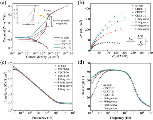
Table 2. The potential ranges used for Tafel extrapolation method.
Table 3. Summary of potentiodynamic polarisation test results of CrCoNi MEA in 3.5 wt% NaCl solution.
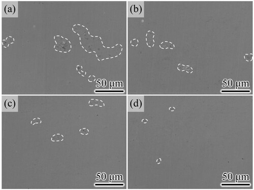
The corrosion morphologies of the samples are shown in to further reflect the effect of CDCT on corrosion resistance. As seen, etch pits are visible in all samples, confirming that the corrosion type of the samples is pitting corrosion. With increasing CDCT cycles, the number and area of the etch pits decreased, which may be related to the high CRS and dense crystalline defects that suppress the localised breaking of the passive film.
Figure 7. SEM images of corrosion morphology of (a) as-built, (b) CDCT-10, (c) CDCT-20, and (d) CDCT-30.
The above results indicate that increasing CDCT cycles is able to improve the corrosion performance of LDED-formed CrCoNi MEA. It is also important to note that CDCT treatments can only reduce the corrosion rate by increasing Ecorr and decreasing Icorr, which prolongs the service life of the LDED-formed parts, but does not suppress the occurrence of pitting behaviour. Crystalline defects and CRS induced by CDCT can promote the formation of a protective passive film. Once the passive film breaks down, it will not be able to prevent the further progression of corrosion damage. Thus, the CDCT samples possess a low passive current density and narrow passive potential range, while their pitting potential and current density were comparable with the as-built one.
3.3.2. Electrochemical impedance spectroscopy
The corrosion resistance of the metallic materials is mainly dependent on the stability of the passive film [Citation35]. Thus, EIS measurement was performed to characterise the properties of the passive film formed in different samples. The obtained Nyquist and Bode plots are presented in (b–d). The inset in (b) shows the fitting electrical equivalent circuit model, which is frequently used for CrCoNi MEA [Citation30]. The electrode system is composed of a solution resistance (Rsol), charge transfer resistance (Rt), and constant phase element (CPE). Among them, the Rsol mainly represents the resistance of the electrolyte solution, Rt refers to the charge transfer resistance of the contact interface between the solution and working electrode, and CPE refers to the capacitance caused by the double layer of this contact interface.
As seen in (b), all the obtained Nyquist plots exhibit a circular arc shape with different radius, indicating their similar passive mechanism. Generally, a larger arc radius suggests a better corrosion resistance of the tested material [Citation36]. Thus, the CDCT-30 possesses the best corrosion resistance among the four samples, consistent with the potentiodynamic polarisation results. The Bode plots for all the samples in (c) exhibit slope of impedance ǀZǀ vs frequency of about −1, implying that the formed passive films possess a capacitive behaviour [Citation37]. In the phase angle vs frequency curves in (d), broadened peaks are observed and the curves are broader at the low-frequency end for the samples subjected to more CDCT cycles; hence, compared with the others, CDCT-30 possesses a stable phase angle over a wider frequency range, suggesting the formation of a more stable passive film [Citation38].
The fitting parameters in the electrical equivalent circuit model are summarised in . The value of charge transfer resistance (Rt) gradually increases with increasing number of CDCT cycles, implying a suppressed oxidation reaction, especially for CDCT-30. The compactness of the passive film is positively correlated with the CPE constant Y0, and the CDCT-30 shows the highest Y0 among the samples, suggesting the formation of a denser passive film [Citation39,Citation40]. The values of α, which represents the depression coefficient (0 < α < 1), are close to 1, indicating that the CPE is approximately an ideal capacitor. According to Shuang’s work [Citation41], a higher α is also indicative of a smooth electrode surface, which is beneficial for forming a uniform and stable passive film.
Table 4. Equivalent circuit fitting parameters for EIS results of as-built, CDCT-10, CDCT-20, and CDCT-30.
Based on the above results, the CDCT-30 exhibits the optimum corrosion resistance among the four samples. The corrosion behaviour of metallic alloys is closely related with the grain size, dislocation density, grain boundary, and precipitates [Citation42–44]. For this work, dense dislocations and nanotwins caused by CDCT are responsible for the improved corrosion properties in the CDCT samples. It was reported that the oxidation reactions of metals preferentially take place in regions with a high dislocation density due to the high activation energy [Citation45]. Therefore, the increased dislocation density within the CDCT samples will facilitate the formation of compact and thick passive film, thus improving the corrosion resistance. The role of nanotwins is achieved through reducing the trend of localised corrosion through their relatively low surface energy [Citation46]. Besides, the significantly increased CRS also plays an important role in improving corrosion resistance, which can inhibit the occurrence of pitting caused by local rupture of the passive film [Citation47].
3.4. Wear properties
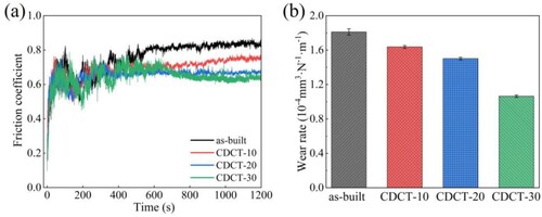
shows the frictional coefficients and wear rates of the samples. As seen in (a), the frictional coefficient vs time curves of the four samples consist of two stages, i.e. a run-in stage and a stable stage. The run-in stage characterised by a dramatical fluctuation in frictional coefficient lasts from the beginning to ∼ 600 s. After that, the stable stage begins until the end of the wear test. In the present work, the average frictional coefficient of each sample was calculated from the recorded data from 800 s to 1200 s, and the results are 0.83, 0.74, 0.67, 0.64 for as-built, CDCT-10, CDCT-20, and CDCT-30, respectively, suggesting improvement of the wear resistance induced by CDCT. The wear rate shown in (b) decreases with increasing number of CDCT cycles, further confirming the beneficial effect of CDCT.
Figure 8. Results of wear tests of as-built, CDCT-10, CDCT-20, and CDCT-30: (a) friction coefficients; (b) wear rates.
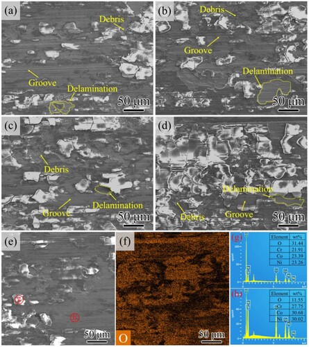
To identify the wear mechanism of the samples, the wear morphologies were examined by SEM and EDS. As shown in (a–d), grooves, debris, and delamination are observed in each sample, indicating that the wear mechanism of the samples are abrasive and adhesive in nature. (e–h) present the EDS results of the wear surface in the as-built sample. The lamellar flakes observed in the wear surface have a high oxygen content, indicating that oxidation wear also occurred during the scratch process. Although they have similar wear behaviours, the four samples have different wear damage levels. As seen in (a), the as-built sample possesses serious wear damage characterised by massive deep grooves, large debris, and oxidised flakes. After the CDCT, the wear surface is significantly changed; the most noticeable difference is that the number of oxidised flakes increases as the number of CDCT cycles increases, as shown in (b–d). Especially for CDCT-30, the oxidised flakes nearly cover the whole wear surface.
Figure 9. SEM images of the wear surfaces of the four samples: (a) as-built, (b) CDCT-10, (c) CDCT-20, and (d) CDCT-30. (f), (g), and (h) are the element analysis of (e) captured in as-built sample.
The reasons for the changed area of oxidised flakes can be explained by Archard’s law, which is expressed as [Citation48]:
(3)
(3) where T is the temperature at the wear surface, f is the frictional coefficient, H is the hardness of the matrix, F is the load used for the wear test, v is the sliding speed, and λ is the thermal conductivity of the matrix. Apparently, the temperature generated during the wear test is closely related to the hardness of the matrix. As mentioned above, the CDCT-30 possesses the highest density of dislocations and nanotwins, and high CRS, thus favouring its higher hardness (3.742 GPa) than the as-built sample (3.713 GPa). Therefore, a high frictional heat is easily generated during the wear test, and the formation of oxide layer is promoted. Furthermore, a locally high temperature leads to a strong oxide layer that covers the wear surface through cold welding [Citation49]. As the oxides of Cr, Co, and Ni possess higher hardness compared with the matrix (CrCoNi MEA), the oxide layer will act as a protective layer to suppress the abrasive and adhesive wear, causing a low frictional coefficient and wear rate.
3.5. Evolution mechanism of microstructure during CDCT
According to the above discussion, the improved corrosion resistance and wear properties of the CDCT-treated samples are caused by the increased CRS and crystalline defects of dislocations and nanotwins. Therefore, it is necessary to depict the microstructural evolution inside the LDED-fabricated CrCoNi MEA during CDCT. To address this issue, the CDCT process is divided into three stages, namely, the cooling stage, holding stage, and rewarming stage. A schematic is proposed to illustrate the variation of residual stress and microstructure during CDCT, as shown in .
Figure 10. The schematic to illustrate the variation of microstructure and residual stress within the LDED-fabricated CrCoNi MEA during CDCT.
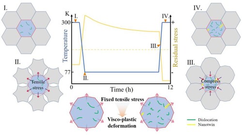
During the cooling stage, significantly thermal contraction occurs, and as the grains are constrained by each other, the contraction is restrained. Therefore, when the cooling stage is over, a high tensile stress will be generated within the grains in the sample interior as illustrated in Ⅱ. Next, in the holding stage, the sample interior with a high tensile stress will be held at 77 K (temperature of liquid nitrogen) for about 12 h, during which dislocations and nanotwins will be gradually generated as a visco-plastic deformation process, which is accompanied by a gradual tensile stress relaxation, as depicted in [Citation18,Citation50]. At the end of the holding stage, a new equilibrium state characterised by crystalline defects and decreased tensile residual stress will be established. During the rewarming stage, the temperature of the sample returns to room temperature and then the sample thermally expands to its initial size, causing a residual CRS within the sample ( Ⅲ). It is noteworthy that the value of the newly formed CRS is higher than that of the as-built state, which can be attributed to the visco-plastic deformation by generation of crystalline defects during the cryogenic holding stage that relaxes the elastic tensile stress on cryogenic immersion, and hence on rewarming the residual stress recovers to an even more compressive value than before the treatment.
Combining the above discussions and the schematic shown in , the mechanisms of the changes in residual stress and microstructure within the LDED-fabricated CrCoNi MEA during one CDCT cycle are clearly delineated. In the next CDCT cycle, the sample is re-immersed into liquid nitrogen again, and the thermal contraction occurs simultaneously leading to a tensile residual stress in the sample interior, which is comparable with that in the former cycle. Since the sample now possesses crystalline defects produced by the former cycle, the visco-plastic deformation during the subsequent cryogenic holding stage will be less than that the former cycle, and hence the stress relaxation will also be less. In any case, further defects of dislocations and nanotwins will still be generated which correspond to the observation in . In the rewarming stage, the recovered residual stress will still be more compressive than the start of the second cycle, but due to the smaller stress relaxation in the holding stage, the differential will be less than that in the first cycle. This explains the saturating trend of the CRS as the number of CDCT cycles increases as shown in (b).
3.6. Relationship between CDCT cycles, microstructure, and properties
Combining the results from the experimental characterisation, electrochemical corrosion tests, and tribological properties tests, it can be concluded that the process of CDCT plays a vital role in improving the corrosion and wear resistance of the LDED-formed CrCoNi MEA. Here, to provide more comprehensive guidance for the future application of CDCT, the process-microstructure-property relationship is described as follows.
For the as-built sample, it has a CRS value of 220.4 ± 18.3 MPa, and its microstructure was characterised by some randomly distributed dislocations ((a)). When the sample subjected to CDCT, a high tensile stress induced by thermal contraction was generated within every grain, causing the crystalline defects, including dislocations and nanotwins, through visco-plastic deformation. Similar results have also been reported in the CDCT-treated Mg alloy, Al alloy, Cu alloy and HEA [Citation13,Citation50–52]. With increasing CDCT cycles, the thermal contraction induced tensile stress became higher due to the existence of crystalline defects produced by the former CDCT cycle, which causing repeated activation of the visco-plastic deformation that generates more and more crystalline defects within the sample. Thus, the increased dislocation density and nanotwins was observed in CDCT-10, CDCT-20, and CDCT-30. Due to the increased crystalline defects, the visco-plastic deformation and the stress relaxation was inhabited, resulting in an increase in CRS, which are 334.9 ± 21.6 MPa, 343.1 ± 22.1 MPa, and 361.9 ± 16.8 MPa for CDCT-10, CDCT-20, and CDCT-30, respectively (220.4 ± 18.3 MPa for the as-built sample).
For the corrosion property of the CDCT-treated samples, the increased crystalline defects facilitated the formation of a compact passive film on the surface of sample and the high CRS suppressed the occurrence of local rupture of passive film, leading to an increased Ecorr and decreased Icorr that significantly slows down the corrosion rate [Citation34]. Compared with the as-built sample, Ecorr was increased by 20.17%, 34.09%, and 37.22% for CDCT-10, CDCT-20, and CDCT-30, respectively, and the Icorr was decreased by 83.08%, 89.23%, and 94.62% for CDCT-10, CDCT-20, and CDCT-30, respectively.
For wear tests, the increased crystalline defects and high CRS caused a high frictional heat on the wear surface. According to Peng and Diao’s work [Citation21,Citation48], the high frictional heat will lead to the formation of an oxide layer with high hardness, and force it to cover on the wear surface by cold welding. With the protection of this oxide layer, the average friction coefficients of CDCT-treated samples decreased by 10.84% (CDCT-10), 19.28% (CDCT-20), and 22.89% (CDCT-30) compared with the as-built sample.
Based on the above discussions and analyzation, the correlation between CDCT cycles, microstructure, and corrosion and wear performances can be clarified as follows: by increasing the CDCT cycles, the LDED-formed CrCoNi MEA will possesses more and more crystalline defects and high CRS, finally leading to the improved corrosion resistance and wear resistance.
4. Conclusion
In this work, the CDCT was selected as a post-fabrication method to regulate the residual stress and microstructure of LDED-fabricated CrCoNi MEA. The effect of the number of CDCT cycles on the residual stress, microstructure and consequently corrosion and wear resistance of the LDED-fabricated MEA were studied. The main conclusions are summarised as follows:
CDCT is an effective post-fabrication method for LDED-fabricated CrCoNi MEA. After subjected to 30 CDCT cycles, the dislocation density within the LDED-fabricated CrCoNi MEA significantly increases, and nanotwins that are not present in the initial state are formed. The CRS of CDCT-30 increases by 64.2% compared to the initial state.
The crystalline defects and high CRS caused by CDCT lead to the formation of dense and thick passive film, resulting in significant improvement of the corrosion resistance of the LDED-fabricated CrCoNi MEA. Compared with the as-built sample, CDCT-30 exhibits a 37% increase in corrosion potential and a 95% reduction in corrosion current density.
Due to the existence of dense crystalline defects and high CRS within the CDCT-treated sample, the frictional heat during wear testing increases dramatically. As a result, a strong oxide layer forms on the wear surface through cold welding, which acts as a protective layer to decrease the friction coefficient and the wear rate, favouring the wear resistance.
The formation of dense dislocations and nanotwins accompanies visco-plastic deformation during the holding stage of CDCT which relaxes the high tensile residual stress set up on cooling to the cryogenic temperature. Then, on rewarming to room temperature, the residual stress in the sample interior recovers to a more compressive value than before the cryogenic treatment. With increasing number of CDCT cycles, the visco-plastic deformation will occur repeatedly, causing more crystalline defects and consequently a higher CRS, although the effect will saturate on large number of cycles.
Disclosure statement
No potential conflict of interest was reported by the author(s).
Data availability statement
The data that support the findings of this study are available from the corresponding author, [YJH], upon reasonable request.
Additional information
Funding
References
- Thompson SM, Bian L, Shamsaei N, et al. An overview of direct laser deposition for additive manufacturing; part I: transport phenomena, modeling and diagnostics. Addit Manuf. 2015;8:36–62. doi:10.1016/j.addma.2015.07.001
- Bi XL, Li RF, Yuan ZJ, et al. Laser-directed energy deposition of a high performance additively manufactured (CoCrNi)94(TiAl)6 medium-entropy alloy with a novel core-shell structured strengthening phase. Addit Manuf. 2024;80:103971. doi:10.1016/j.addma.2024.103971
- Wang G, Zhao HD, Liang HY, et al. Multi-objective optimisation of process parameters for laser-based directed energy deposition of a mixture of H13 and M2 steel powders on 4Cr5Mo2SiV1 steel. Virtual Phys Prototyp. 2024;19(1):2290184. doi:10.1080/17452759.2023.2290184
- Lu XF, Zhang GH, Chiumenti M, et al. Smart-substrate: a novel structural design to avert residual stress accretion in directed energy deposition additive manufacturing. Virtual Phys Prototyp. 2023;18(1):2246041. doi:10.1080/17452759.2023.2246041
- Chen YF, Lu TW, Chen XY, et al. Optimized bilateral ultrasonic surface rolling process assisting directed energy deposition of thin-walled medium-entropy alloy with high mechanical performance. Addit. Manuf. 2023;78:103887. doi:10.1016/j.addma.2023.103887
- Li ZT, Ma SH, Zhao SJ, et al. Achieving superb strength in single-phase FCC alloys via maximizing volume misfit. Mater Today. 2023;63:108–119. doi:10.1016/j.mattod.2023.02.012
- Fu WJ, Sun YG, Fan GH, et al. Strain delocalization in a gradient-structured high entropy alloy under uniaxial tensile loading. Int J Plast. 2023;171:103808. doi:10.1016/j.ijplas.2023.103808
- Fu WJ, Huang YJ, Sun JF, et al. Strengthening CrFeCoNiMn0.75Cu0.25 high entropy alloy via laser shock peening. Int J Plast. 2022;154:103296. doi:10.1016/j.ijplas.2022.103296
- Cui X, Zhang S, Wang C, et al. Effects of stress-relief heat treatment on the microstructure and fatigue property of a laser additive manufactured 12CrNi2 low alloy steel. Mater Sci Eng A. 2020;791:139738. doi:10.1016/j.msea.2020.139738
- Gao Q, Jiang XS, Sun HL, et al. Effect mechanism of cryogenic treatment on ferroalloy and nonferrous alloy and their weldments: a review. Mater Today Commun. 2022;33:104830. doi:10.1016/j.mtcomm.2022.104830
- Kumar TV, Thirumurugan R, Viswanath B. Influence of cryogenic treatment on the metallurgy of ferrous alloys: a review. Mater Manuf Processes. 2017;32(16):1789–1805. doi:10.1080/10426914.2017.1317790
- Yao E, Zhang HJ, Ma K, et al. Effect of deep cryogenic treatment on microstructures and performances of aluminum alloys: a review. J Mater Res Technol. 2023;26:3661–3675. doi:10.1016/j.jmrt.2023.08.140
- Li K, Chen W, Yin BZ, et al. A comparative study on WE43 magnesium alloy fabricated by laser powder bed fusion coupled with deep cryogenic treatment: evolution in microstructure and mechanical properties. Addit Manuf. 2023;77:103814. doi:10.1016/j.addma.2023.103814
- Zhao RX, Chen CY, Shuai SS, et al. Enhanced mechanical properties of Ti6Al4 V alloy fabricated by laser additive manufacturing under static magnetic field. Mater Res Lett. 2022;10(8):530–538. doi:10.1080/21663831.2022.2064195
- Wang R, Wang J, Cao TW, et al. Microstructure characteristics of a René N5 Ni-based single-crystal superalloy prepared by laser-directed energy deposition. Addit Manuf. 2023;61:103363. doi:10.1016/j.addma.2022.103363
- Li HG, Che PC, Yang XK, et al. Enhanced tensile properties and wear resistance of additively manufactured CoCrFeMnNi high-entropy alloy at cryogenic temperature. Rare Met 2022;41(4):1210–1216. doi:10.1007/s12598-021-01867-1
- Zhou CA, Sun QD, Qian DQ, et al. Effect of deep cryogenic treatment on mechanical properties and residual stress of AlSi10Mg alloy fabricated by laser powder bed fusion. J Mater Process Technol 2022;303:117543. doi:10.1016/j.jmatprotec.2022.117543
- Li HG, Huang YJ, Zhao WJ, et al. Overcoming the strength-ductility trade-off in an additively manufactured CoCrFeMnNi high entropy alloy via deep cryogenic treatment. Addit. Manuf. 2022;50:102546. doi:10.1016/j.addma.2021.102546
- Gludovatz B, Hohenwarter A, Thurston KVS, et al. Exceptional damage-tolerance of a medium-entropy alloy CrCoNi at cryogenic temperatures. Nat Commun. 2016;7(1):10602. doi:10.1038/ncomms10602
- Zhao WJ, Sun YG, Che PC, et al. The columnar to equiaxed transition of CoCrNi medium-entropy alloy fabricated by laser directed energy deposition. Mater Des. 2024;237:112538. doi:10.1016/j.matdes.2023.112538
- Peng ZL, Zhang XY, Zhang Y, et al. Wear resistance enhancement of inconel 718 via high-speed ultrasonic vibration cutting and associated surface integrity evaluation under high-pressure coolant supply. Wear. 2023;530-531:205027. doi:10.1016/j.wear.2023.205027
- Wu T, Ren YJ, Liang LX, et al. Tensile strength and wear resistance of glass-reinforced PA1212 fabricated by selective laser sintering. Virtual Phys Prototyp. 2023;18(1):2150652. doi:10.1080/17452759.2022.2150652
- Zou X, Chang TF, Yan Z, et al. Control of thermal strain and residual stress in pulsed-wave direct laser deposition. Opt Laser Technol. 2023;163:109386. doi:10.1016/j.optlastec.2023.109386
- Tong ZP, Ren XD, Jiao JF, et al. Laser additive manufacturing of FeCrCoMnNi high-entropy alloy: effect of heat treatment on microstructure, residual stress and mechanical property. J Alloys Compd. 2019;785:1144–1159. doi:10.1016/j.jallcom.2019.01.213
- Bai PK, Wang J, Zhao ZY, et al. Microstructure and mechanical properties of Mg-Gd-Y-Zn-Zr alloy fabricated by cold metal transfer wire arc additive manufacturing. J Mater Res Technol. 2023;27:5805–5821. doi:10.1016/j.jmrt.2023.10.265
- Liu M, Zheng Q, Wang X, et al. Characterization of distribution of residual stress in shot-peened layer of nickel-based single crystal superalloy DD6 by nanoindentation technique. Mech Mater. 2022;164:104143. doi:10.1016/j.mechmat.2021.104143
- Sahami-Nejad M, Lashgari HR, Zangeneh S, et al. Determination of residual stress on TIG-treated surface via nanoindentation technique in Co-Cr-Mo-C alloy. Surf Coat Technol. 2019;380:125020. doi:10.1016/j.surfcoat.2019.125020
- Suresh S, Giannakopoulos AE. A new method for estimating residual stresses by instrumented sharp indentation. Acta Mater. 1998;46(16):5755–5767. doi:10.1016/S1359-6454(98)00226-2
- Zhou KX, Cui DC, Chai ZS, et al. In-situ tailoring microstructures to promote strength-ductility synergy in laser powder bed fusion of NiCoCr medium-entropy alloy. Addit Manuf. 2023;66:103443. doi:10.1016/j.addma.2023.103443
- Weng F, Chew YX, Ong WK, et al. Enhanced corrosion resistance of laser aided additive manufactured CoCrNi medium entropy alloys with oxide inclusion. Corros Sci. 2022;195:109965. doi:10.1016/j.corsci.2021.109965
- Zhang ZJ, Yuan TC, Li RD. Corrosion performance of selective laser-melted equimolar CrCoNi medium-entropy alloy vs its cast counterpart in 3.5 wt%. NaCl. J Alloys Compd. 2021;864:158105. doi:10.1016/j.jallcom.2020.158105
- Feng K, Zhang Y, Li ZG, et al. Corrosion properties of laser cladded CrCoNi medium entropy alloy coating. Surf Coat Technol. 2020;397:126004. doi:10.1016/j.surfcoat.2020.126004
- Feng H, Li HB, Wu XL, et al. Effect of nitrogen on corrosion behaviour of a novel high nitrogen medium-entropy alloy CrCoNiN manufactured by pressurized metallurgy. J Mater Sci Technol. 2018;34(10):1781–1790. doi:10.1016/j.jmst.2018.03.021
- Wetzel A, von der Au M, Dietrich PM, et al. The comparison of the corrosion behavior of the CrCoNi medium entropy alloy and CrMnFeCoNi high entropy alloy. Appl Surf Sci. 2022;601:154171. doi:10.1016/j.apsusc.2022.154171
- Moravcik I, Peighambardoust NS, Motallebzadeh A, et al. Interstitial nitrogen enhances corrosion resistance of an equiatomic CoCrNi medium-entropy alloy in sulfuric acid solution. Mater Charact. 2021;172:110869. doi:10.1016/j.matchar.2020.110869
- Wang D, Huang JH, Tan CL, et al. Mechanical and corrosion properties of additively manufactured SiC-reinforced stainless steel. Mater Sci Eng A. 2022;841:143018. doi:10.1016/j.msea.2022.143018
- Lu Z, Zhang CC, Fang RR, et al. Microstructure evolution and corrosion behavior of the novel maraging stainless steel manufactured by selective laser melting. Mater Charact. 2022;190:112078. doi:10.1016/j.matchar.2022.112078
- Xia C, Chen K, Chen BH, et al. Microstructure evolution, mechanical properties, and corrosion behavior of novel (50Zr–50Ti)-xNi ternary alloys. Mater Sci Eng A. 2022;846:143308. doi:10.1016/j.msea.2022.143308
- Luo H, Li ZM, Mingers AM, et al. Corrosion behavior of an equiatomic CoCrFeMnNi high-entropy alloy compared with 304 stainless steel in sulfuric acid solution. Corros Sci. 2018;134:131–139. doi:10.1016/j.corsci.2018.02.031
- Wu PF, Gan KF, Yan DS, et al. A non-equiatomic FeNiCoCr high-entropy alloy with excellent anti-corrosion performance and strength-ductility synergy. Corros Sci. 2021;183:109341. doi:10.1016/j.corsci.2021.109341
- Shuang S, Ding ZY, Chung D, et al. Corrosion resistant nanostructured eutectic high entropy alloy. Corros Sci. 2020;164:108315. doi:10.1016/j.corsci.2019.108315
- Jiang B, Wang C, Song RG, et al. Effect of creep ageing on the corrosion behaviour of an Al–Cu–Li alloy. Corros Sci. 2022;202:110314. doi:10.1016/j.corsci.2022.110314
- Ma JW, Zhang BC, Fu Y, et al. Effect of cold deformation on corrosion behavior of selective laser melted 316L stainless steel bipolar plates in a simulated environment for proton exchange membrane fuel cells. Corros Sci. 2022;201:110257. doi:10.1016/j.corsci.2022.110257
- Qi X, He YF, Jiang B, et al. Effect of deformation and annealing on microstructure and corrosion behavior of 7075 aluminum alloy with micro arc oxidation coating. Surf Coat Technol. 2023;469:129791. doi:10.1016/j.surfcoat.2023.129791
- Sun M, Xiao K, Dong CF, et al. Effect of stress on electrochemical characteristics of pre-cracked ultrahigh strength stainless steel in acid sodium sulphate solution. Corros Sci. 2014;89:137–145. doi:10.1016/j.corsci.2014.08.023
- Gerashi E, Alizadeh R, Langdon TG. Effect of crystallographic texture and twinning on the corrosion behavior of Mg alloys: a review. J Magnes Alloy. 2022;10(2):313–325. doi:10.1016/j.jma.2021.09.009
- Xu JP, Liu CZ, Wu JP, et al. New insight into the role of microscale residual stresses on initial corrosion behavior of Ti35 alloy. Corros Sci. 2022;206:110491. doi:10.1016/j.corsci.2022.110491
- Diao GJ, He AQ, Tang YQ, et al. Effects of Al and Ti on microstructure, mechanical properties and wear resistance of TiXCrFe2Ni2 alloys. Mater Sci Eng A. 2023;879:145242. doi:10.1016/j.msea.2023.145242
- Cao F, Cui HZ, Song XJ, et al. Fabrication of multi-scale TiC and stainless steel composite coatings via circular oscillating laser towards superior wear and corrosion resistance of aluminum alloy. J Mater Sci Technol. 2024;177:191–204. doi:10.1016/j.jmst.2023.07.072
- Li HG, Zhao WJ, Chen T, et al. Beneficial effects of deep cryogenic treatment on mechanical properties of additively manufactured high entropy alloy: cyclic vs single cryogenic cooling. J Mater Sci Technol 2022;115:40–51. doi:10.1016/j.jmst.2021.11.022
- Jovičević-Klug M, Rezar R, Jovičević-Klug P, et al. Influence of deep cryogenic treatment on natural and artificial aging of Al-Mg-Si alloy EN AW 6026. J Alloys Compd 2021;899:163323. doi:10.1016/j.jallcom.2021.163323
- Liu K, Chen XZ, Shen QK, et al. Microstructural evolution and mechanical properties of deep cryogenic treated Cu–Al–Si alloy fabricated by cold metal transfer (CMT) process. Mater Charact 2019;159:110011. doi:10.1016/j.matchar.2019.110011