
ABSTRACT
In this study, a series of Acrylate-Styrene-Acrylonitrile (ASA) composites loaded with high amounts of cork agro-waste (10–30 wt.%) are developed to address the increasing demand from industry and society for more sustainable materials, with the aim of reducing the carbon footprint associated with fossil fuel-derived plastics. These materials are suitable for Material Extrusion (ME) technologies, including Large Format Additive Manufacturing (LFAM). We demonstrate that the printing conditions can be optimised to manufacture cork composites with good mechanical properties, even for large particle sizes, around 1 mm. Sustainability analysis of these composites revealed that the carbon footprint can be reduced by up to 25% for composites with 30 wt.% cork, primarily due to the reduction in ASA usage. These composites were used to print a luminaire utilising a biomimetic approach and parametric design, showcasing how new materials and innovative product design can be integrated to produce functional and sustainable prototypes.
1. Introduction
Large Format Additive Manufacturing (LFAM) is defined as those AM technologies that enable the production of parts larger than 1 m³ [Citation1]. The most widespread techniques within LFAM are based on material extrusion (ME), which involve the deposition of molten thermoplastic material to manufacture an object layer by layer, based on a computer-generated design. This thermoplastic material can be in the form of filament (Fused Filament Fabrication, FFF) or pellets (Fused Granular Fabrication, FGF). Generally, FGF technologies are preferred for LFAM due to their higher deposition rates, wide range of available materials (including composites) and shorter production times [Citation2,Citation3]. LFAM is currently implemented in industrial sectors such as aerospace, naval, automotive, architecture and interior design [Citation4–7].
Although bio-based polymers such as polylactic acid (PLA) can be used, fossil fuel-derived engineering polymers such as Acrylonitrile–Butadiene–Styrene (ABS), Acrylonitrile–Butadiene-Acrylate (ASA), polyamide (PA) or polyethylene terephthalate (PET) are preferred for industrial applications due to their superior mechanical and thermomechanical properties. There are several strategies to improve the sustainability of these polymers, such as increasing the amount of recycled content, substituting them with bio-based polymers, or developing bio-based composites using waste biomass as feedstock [Citation8]. In these composites, the natural filler ranges typically from 5 to 25 wt.% but can exceed 50 wt. % [Citation9]. This reduces plastic content and valorises agro-waste into new products. Examples of natural agro-waste fillers include natural fibres, wood powder and husks [Citation10]. In the particular case of Western Mediterranean countries, such as Spain and Portugal, there is a growing interest in using cork for these applications due to its high regional production [Citation11,Citation12].
Cork is a natural material with an open cellular structure that contributes to reducing the weight of polymer composites, making them lighter and more thermally insulating [Citation13–16]. Cork is primarily used in the production of wine bottle stoppers, as an insulator in the construction sector due to its thermal and acoustic properties, and in the textile sector for footwear, clothing and accessories. However, the manufacturing processes of stoppers and panels generate a significant amount of cork waste, up to 30 wt.% of the starting material, which is typically incinerated. Consequently, there is considerable interest in the industrial-scale valorisation of cork waste, due to the large quantities [Citation13,Citation14,Citation17]. Moreover, the valorisation of cork waste can impart a distinctive aesthetic to the base material, as the inherent colour and particle size of the cork become visibly integrated into the surface of the final product, enhancing its natural and organic appearance.
Various authors have reported the development of composites containing up to 50 wt.% cork, using matrices such as high-density polyethylene (HDPE), medium density polyethylene (MDPE) or PLA, and employing conventional manufacturing technologies such as extrusion or injection moulding [Citation10,Citation16,Citation18]. In these studies, cork particles with diameters of up to 0.5 mm were used. The application of cork composites in AM technologies has also been explored, although to a lesser extent. Previous studies, including those by our research group, have reported cork composites for stereolithography [Citation19] and FFF [Citation20–22]. However, in all these cases, the cork content was below 5 wt.% and smaller particle sizes, typically below 200 µm, were used to prevent printing issues as clogging. This limitation restricts the amount of cork that can be incorporated, needing larger amounts of fossil fuel-derived plastic. Commercial filaments [Citation23] based on PLA with a reported cork content of 20 wt.% are also available. In this case, the manufacturer recommends using nozzles with a minimum diameter of 0.6 mm to prevent clogging, highlighting the critical role of the nozzle size in the printing process.
Cork can also be integrated, from a product design engineering perspective, with biomimetics to develop new products inspired by natural shapes and textures. This approach has already been adopted in various industries such as automotive [Citation24], construction [Citation25], and interior design [Citation26], among others. Biomimetics involves emulating the structures found in natural materials (e.g. wood) to enhance the structural performance of artificially manufactured objects [Citation27,Citation28]. Parametric design software like Rhinoceros with the Grasshopper plugin enables the generation of geometric designs linked to specific printing parameters, facilitating the customisation of diverse products. These tools are widely used in architecture, enabling the creation of items ranging from glasses to building interiors. Combining biomimetics with AM allows for the creation of unique surface textures, leveraging the layered geometry inherent in printed objects, resulting in a laminated finish [Citation26,Citation29–33].
In summary, various studies have shown the feasibility of developing polymer-based composites loaded with cork (or other agro-waste) with contents up to 50 wt.% using conventional manufacturing techniques like injection moulding. However, limited studies in AM, and particularly in LFAM, present an opportunity for further exploration. In this context, this study investigates the potential of ASA-cork composites in LFAM. Utilising a FGF printer equipped with a 2 mm nozzle, composites containing up to 30 wt.% cork were successfully printed, using particle sizes ranging from 0.4 to 0.8 mm. The dispersion of cork particles within the ASA matrix was assessed by X-ray tomography and electron microscopy, correlating their distribution with the density and mechanical properties of the composites. This research integrates the processability of these materials with an innovative design approach tailored for AM, employing a biomimetic parametric design in the creation of a luminaire. This product, shown as a proof of concept, illustrates how the use of natural materials can be combined with bioinspired design to manufacture new functional, more sustainable and attractive products for the consumer.
2. Materials and methods
2.1. Materials
ASA pellets (general purpose ASA for injection moulding, density 1.07 g/cm3, melt mass-flow rate 12 g/10 min (220°C/10.0 kg)) were purchased from LG Chem, South Korea. Cork powder, obtained from cork waste from the sanding processes during the manufacture of cork stoppers, were provided by Corchos del Estrecho (Alcalá de los Gazules, Cádiz, Spain). The cork was originally obtained from the bark of oaks of the same region (Alcornocales Natural Park in the province of Cádiz) and same production batch to minimise the impact of possible variation in the properties from batch to batch. This cork powder was previously sieved and separated in two granulometric distributions: one with a nominal particle size of 0.4–0.8 mm (fine cork powder, FC) and other with 0.8–1.8 mm (coarse cork powder, CC).
2.2. Processing
ASA and cork waste were dried in a Piovan DPA dehumidifying dryer at 80°C for 4 h before processing. Cork composites with 10, 15, 20, 25 and 30 wt.% FC or CC were synthesised in a twin screw extruder operated at 250 rpm with a temperature profile of 200/215°C. In all cases, the obtained filaments were immediately introduced into a water-cooling system and subsequently cut in a Scamex pelletizer to obtain the composites in the form of pellets. These amounts were chosen considering our previous work, where 5 wt.% cork composites were successfully printed [Citation22], aiming to further increase the amount of cork waste and decrease the ASA content. To this end, the impact of varying cork concentrations was studied, starting at 10 wt.% and increasing by 5 wt.% increments to closely observe the effects of cork content. Cork concentrations above 30 wt.% were not tested because they caused nozzle clogging while printing, thus identifying 30 wt.% as the upper limit for cork content in this work.
The composites were then dried again under the same conditions and used as feedstock in a FGF Discovery 3D Granza machine purchased from Bárcenas CNC. Two types of plates were printed in the XY and XZ plates according to ISO/ASTM 52921 to evaluate the mechanical properties of the compounded materials (see Figure S1) [Citation34]. The parameters used for printing the specimens were a bead width of 2 mm, layer height of 1 mm, and printing speeds of 50 mm/s for the horizontal plates and 25 mm/s for the vertical plates. Under these conditions, the shear rate of the polymer melt after leaving the printer nozzle is estimated to be around 100 s−1, in agreement with previous studies done in LFAM [Citation35–37]. The printing temperatures optimised for each material are shown in . All the processing temperatures tested to find the optimised conditions for each material are presented in Table S1. The temperatures indicated in correspond to three different heating zones of the printing extruder, where the first value corresponds to the heater furthest to the printing nozzle (see Figure S2). In all cases, the platform temperature was set to 100°C, in order to ensure a good adhesion of the first layer and avoid warping. Digital images of all the printed plates are presented in Figures S3 and S4.
Table 1. List of the different composites used in this study, indicating cork content and printing temperatures. Composites prepared with fine cork particles are labelled as FC while those prepared with coarse cork particles are labelled as CC.
2.3. Specimen machining
A LEKN(C1) 3020 CNC Router Machine Kit CNC was used to cut the normalised specimens for tensile testing out of the printed plates, according to ISO 527 standards and parallelepipeds of 8 × 2 × 0.2 cm3 to measure the density of the composites. For the X-ray computed tomography (XCT) scanning, cubes of 1 cm3 were machined from a 70 × 50 × 10 mm3 plate. A 2 mm diameter flat milling cutter with two cutting edges was used to machine the specimens at a speed of 5000 rpm and a feed rate of 300 mm/min, following a protocol previously optimised by us and others [Citation34,Citation38–40]. Figure S5 shows that the specimens were cut with minimal material chipping and without any observed delamination of the panels or other significant issues that could affect the mechanical testing or other experiments.
2.4. Characterisation
A PCE-XXM30 colorimeter (PCE Ibérica) with a measurement aperture of 8 mm and an exposure time of 1.5 s was used to measure the colour of the samples in the CIELAB colour space. For each material average L, a and b values were obtained. At least three measurements of each material were carried out in the colorimeter tests in order to ensure the reproducibility of the results. The density of the printed parts was measured in three independent samples of 8 × 2 × 0.2 cm3 using a Dahometer DH300. The influence of cork particles (0.2 g/cm³) and ASA (1.07 g/cm³), as well as the possible crushing of cork particles during processing, on the overall density of the composites was studied. The experimental results were compared with those predicted theoretically by applying the rule of mixtures [Citation22]. XCT scanning was carried out using a Zeiss Xradia 610 Versa X-ray microscope (Carl Zeiss X-ray Microscopy). At least two scans were recorded for most of the samples, with optical magnifications of 0.39 and 3.97 and a voxel size resolution of 2.5 µm3. The working accelerating voltage was 50 kV. A total of 1000–2000 2D projections were recorded as the sample was rotated by 360° and computationally reconstructed via a filtered back projection algorithm (Zeiss XM Reconstructor). To visualise the internal features inside the sample in 3D space, the software DragonFly (Object Research Systems) was used. The influence of processing on the morphology of the cork particles was assessed by examining the surface of the pellets and tensile-tested specimens by scanning electron microscopy (SEM) in a FEI Nova NanoSEM 450 microscope equipped with a field emission gun. Specimens were previously sputtered in a Balzers SCD 004 Sputter Coater for 20 s resulting in a ca. 10 nm Au layer. The study was carried out of the surface of the XY specimens. For this purpose, ASA10FC, ASA10CC and ASA30FC were analysed. The mechanical characterisation of the printed specimens was carried out on the Shimadzu AGS-X machine using a constant speed of 2 mm/s, in agreement with ISO 527. At least five specimens of each material were tested. The experimentally obtained Young’s modulus and tensile strength results were compared with theoretical calculations applying the rule of mixtures, as previously reported [Citation26].
An environmental impact analysis of the cork composites was conducted using the EdoAudit tool of the Ansys Granta Edupack software. The contributions from material synthesis, processing and transport were evaluated for each material. Carbon footprint data for ASA and cork were sourced from the software database, assuming ASA was 100% virgin material. Extrusion was considered as the processing method for the compounding of the composites in the twin-screw extruder and the printing by FGF. The compounding step was not included in the analysis in the case of pure ASA. ASA was considered to be transported by ship from South Korea, while road transport from Alcalá de los Gazules (Spain) was selected for cork.
2.5. Parametric design and 3D printing of a luminary
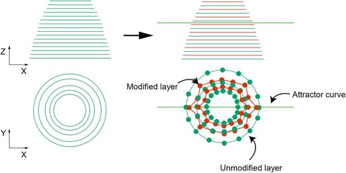
All the parametric design of the luminaire as the case of study was modelled with the software Rhinoceros V7 and his plugin Grasshopper. In the code generated in Grasshopper, a series of parameters were defined for our particular case. The height of the luminaire was 200 mm, printed in the Z direction. The minimum and maximum diameter of the upper and lower circumferences forming the base surface were 21 and 80 mm, respectively. The layer height was 1.5 mm, corresponding to the print layer height. A texture created by modifying the trajectory of each of the printing layers is applied to this luminaire. For this purpose, each layer is divided into 150 equidistant points, which are displaced 10 mm alternately in the XY plane. In this way, a new trajectory is generated for each layer. The points are moved more or less depending on an external curve that attracts the nearby points, defined as Attractor curve, which will move more those points that are closer to the curve. For this luminaire, it was defined as a combination of layers following a 1/1/0 pattern, where 1 refers to a modified layer, and 0 to the unmodified layer. The unmodified layers are the result of creating a polygonal chain (polyline) with the 150 points of the layer, resulting in a perfectly circular layer, while the modified layers are the result of creating the polyline with the modified points, creating a non-circular-shaped layer. This pattern was repeated throughout the entire luminaire. A simplified image of the texturing process is shown in . Once the design is completed, the 3D model was exported in a STL file and loaded in the 3D printing software Simplify3D. Then, the luminaire was printed using ASA25CC, a layer height of 1.5 mm, a bead width of 3.5 mm and the temperature profile previously optimised, as indicated in . A more detailed explanation of the whole design process will be provided in the Results and Discussion section.
Figure 1. Simplified representation of the texturing design with an Attractor curve. The unmodified layers and dots are shown in green while those that were modified by using the Attractor curve are coloured in red.
3. Results and discussion
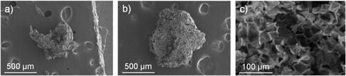
First, SEM of FC and CC was carried out to corroborate their actual size. (a,b) shows an illustrative example of FC and CC, respectively. More SEM images can be found in Figure S6. The aspect ratio of the particles is in general spherical, although some elongated particles can also be observed. The internal structure of the particles is also presented in (c), revealing that the cork waste keeps its original cellular structure. This morphology confers cork with unique properties as thermal insulation and lightweight, making it an interesting candidate for its use in the building industry, interior design and architecture applications. FC and CC presented average particle sizes of 0.72 ± 0.32 mm and 1.02 ± 0.5 mm, respectively, in agreement with the theoretical nominal sizes after sieving.
Figure 2. SEM images of (a) FC, (b) CC and (c) internal structure of FC.
After measuring the incorporated cork particles, the printing tests are initiated to determine the optimal printing temperature for each composite shown in . A temperature of 245°C was first selected since this is the recommended temperature for ASA by the manufacturer and previous reports suggest that cork composites can be processed at this temperature without any significant degradation that could affect the mechanical properties of the material [Citation18,Citation22]. ASA10FC was tested in the first place, given its lower cork content and smaller particle size, which is expected to minimize any clogging issues. Unexpectedly, ASA10FC could not be printed properly under these conditions, manifesting a markedly rough finish and degraded appearance. This result contrasts with our previous study, where 5 wt.% cork ASA composites were printed at 240°C without significant problems [Citation22]. The difference may be attributed to the larger particle size and higher cork content used in this work, as both factors potentially contribute to further cork degradation during the printing process. To solve this problem, the extrusion temperature was adjusted to 225°C, resulting in the successful printing of ASA10FC and ASA15FC under these conditions. However, for ASA20FC, ASA25FC and ASA30FC, the printing temperature had to be further reduced to 210°C. A similar approach was followed for CC composites where, in general, similar temperature profiles were followed in all cases (see Table S1 for more details). This evidences that the amount of cork has a greater influence on the processability by FGF than the cork size used in this work. However, the influence of cork particle size seems to have a higher influence in the processability of the composites with high amounts of cork, since the ASA30CC composite could not be printed.
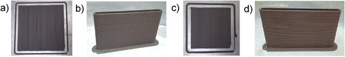
Once the temperatures were optimised, the XY and XZ plates (see Figure S1) were printed without problems. An illustrative example of XY and XZ plates of ASA10CC and ASA30FC are shown in . The rest of the plates are shown in Figures S3 and S4 and all the tensile testing specimens are presented in Figure S5. No clogging or degradation issues occurred during the printing of none of these objects, and the tensile testing specimens were machined without any sheet cracking or other fractures.
Figure 3. 3D-printed (a) ASA10CC XY plate; (b) ASA10CC XZ plate; (c) ASA30FC XY plate and (d) ASA30FC XZ plate.
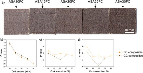
The colour of the printed composites is a uniform brown colour without irregularities or areas of different colour intensity visible to the naked eye. Taking into account that ASA is white, it seems clear that the cork is distributed homogeneously in the composite. The colour appears slightly darker on the printed pieces than on the original pellets, so some minor degradation may have occurred. Previous reports indicate that cork can undergo colour changes due to the partial decomposition of low molecular weight hemicellulose, lignin and suberin at temperatures above 200°C, without this necessary leading to a loss of its mechanical properties [Citation18,Citation22]. The colour of the composites was quantified using a colorimeter that allows obtaining numerical data of the parameters L*, a* and b* of the CIELAB colour space. (a) shows a digital image of ca. 30 × 30 mm2 surfaces of all the FC composites taken under the same exposure conditions, where the greater the cork amount, the darker the composite is. (b–d) shows the Lab values for these composites. The values of a* and b*, corresponding to the colour tone (a*, green-magenta axis and b*, blue–yellow axis) remain practically constant, considering that they can vary from –128 to 127. However, the value of L*, which represents lightness (i.e. brightness or whiteness) shows a clear decreasing linear trend as the cork content increases. This implies that the colour of the material could be tuned with the amount of cork used, regardless of the particle size. This, together with the roughness that the large cork particles give to the surface of the printed parts, allow customising the aesthetic properties when designing products, as it will be evidenced later, when the prototype is designed.
Figure 4. (a) Digital image of all FC composites and results of Lab colour scale values from printed plates. All the images were taken under the same exposure conditions to facilitate direct comparison by naked eye; (b) L* value; (c) a* value and (d) b* value of the cork composites in the CIELAB colour space.
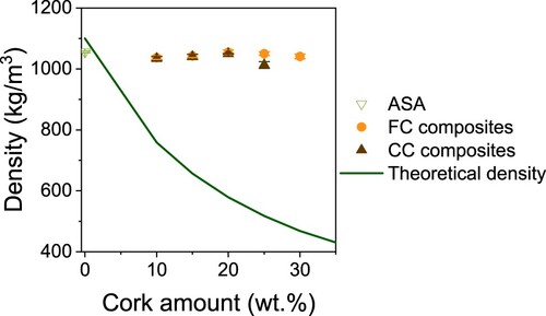
Then, the density of the printed plates was measured. shows that the amount and size of the cork particles does not affect at all to the density of the composites, although they have a very low density (ca. 200 kg/m3) and the predicted values calculated by the rule of mixtures for these composites (included as well in the ) are much lower than those obtained experimentally. Therefore, this suggests that the cork particles may have lost their cellular structure and collapsed during the processing or printing of the composites. This effect has been previously reported when HDPE composites were manufactured by compression moulding using high amounts of cork, between 15 and 50 wt.%, [Citation10,Citation41] and PLA composites manufactured by FFF loaded with 15 wt.% cork particles [Citation42]. However, a significant decrease in the density was also observed in our previous work using ASA composites loaded with 5 wt.% cork particles [Citation22].
Figure 5. Density of ASA, FC composites and CC composites. The theorical density of the composites predicted by the rule of mixtures is also presented with a green solid line.
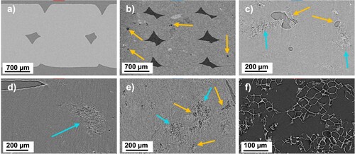
For this reason, ASA, ASA10FC, ASA10CC and ASA30FC printed specimens were studied by XCT scanning, to see the cork distribution within the printed composites and try to explain the high density of the cork composites. These samples were selected to address the influence of both the cork content and the particle size. (a,b) show a comparative at low magnification of the cross section of two printed parts of ASA and ASA10FC, respectively, where the printing beads can be observed. It is worth noting that, in the case of ASA10FC, additional porosity of smaller size can be observed, which must be related to the presence of FC particles, since this is not seen in pure ASA. An analysis at higher magnification in (c) shows that this porosity in turn presents two types of morphology. On the one side, there is a series of voids of 45–200 µm diameter, indicated with orange arrows. Next to these voids, some particles with size in the range of several hundred microns and showing certain porosity (indicated with blue arrows) are also observed, corresponding to the cork additives. Interestingly, these particles observed in (c) are smaller in size than the theoretical FC value, and their porosity is minimal, with a lower cell size than that previously observed in (c). This suggests that the cork particles have been crushed during the printing process, or during the compounding of the composites. The same behaviour is observed in samples of ASA10CC and ASA30FC, (see (d,e)), where the cork particles, both FC and CC, are also observed crushed and often next to larger voids. These larger voids (orange arrows) are probably due to the lack of compatibility between the cork particles and the ASA matrix, as we had previously observed [Citation22]. As a control, an XCT image of a cork particle is also shown, where its porous structure, which is not seen in the composites, is clearly visible. Additional XCT images are included in Figure S7. Thus, it can be deduced that, although the composites have the cork well integrated into the polymer matrix, its cellular structure has almost disappeared after printing, explaining why the density of the composites is virtually the same as that of pure ASA.
Figure 6. XCT images of (a) ASA; (b) ASA10FC; (c) ASA10FC; (d) ASA10CC; (e) ASA30FC and (f) FC; blue arrows mark cork and orange arrows porosity next to the cork particles.
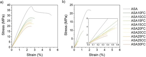
Then, the mechanical properties of the cork composites were studied by tensile testing. shows representative stress–strain curves of these materials where it is observed a similar decreasing trend in the properties of the XY and XZ specimens when the cork amount increases. For instance, XY-printed ASA specimens reach 5% deformation at break while all the cork composites break at strains below 3%, after a small plastic deformation of the material. However, this plastic deformation is not virtually observed for any of the XZ-printed cork composites due to the delamination of the material. This is likely caused by the poor compatibility between the cork particles and ASA, favouring fracture points starting at their interface.
Figure 7. Representative stress-strain curves of (a) XY and (b) XZ printed specimens prepared by FGF.
For a clearer interpretation, the Young’s modulus, tensile strength and elongation at break values were extracted from all the specimens tested (at least five for each material) and are presented in as a function of the cork content (see Figures S8–S13 and Table S2 for more details). The Young’s modulus decreases in all the cork composites when compared to pure ASA with a similar trend for both XY and XZ specimens. However, there is not a clear trend whether it decreases when the cork content increases, implying that using higher cork contents does not have a significant impact on the stiffness of the material, probably because of the densification of the particles during the manufacturing. A similar effect is observed for the tensile strength and elongation at break. A big decrease in these mechanical properties is observed when either FC or CC is introduced in the ASA matrix, but the differences between the composites with either 10 or 30 wt.% cork are not so large, except in the case of the tensile strength of XY specimens where a linear trend is observed when the cork content increases. Small differences are also observed between FC and CC, indicating that CC composites present slightly lower mechanical properties. This can be attributed to the larger size of the particles, which may favour the initiation and propagation of cracks at their interface with ASA. However, often these differences are not significant when compared to FC.
Figure 8. (a) Young’s modulus, (b) tensile strength and (c) elongation at break values of XY - and XZ-printed cork composites. The upper and lower bounds of Young’s modulus and tensile strength predicted by the rule of mixtures are also indicated in (a) and (b) as light green (Theoretical lower bound) and dark green (Theoretical upper bound) lines.
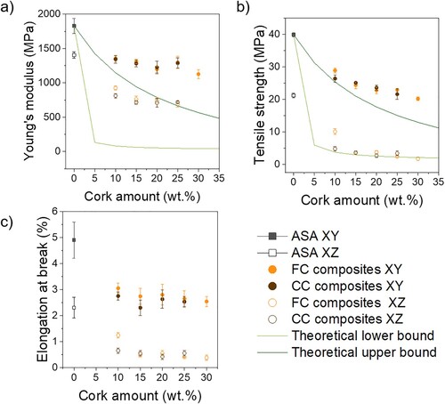
It must be considered that cork is not used in this work as a reinforcing additive (as, for instance, carbon fibre) but to decrease the amount of ASA used, making the material more sustainable. Cork has, in fact, a worse mechanical behaviour than ASA, so a decrease in these properties is expected. For a better understanding, a theoretical estimation of the Young’s modulus and tensile strength of the cork composites was carried out using the rule of mixtures. The calculations were done using the ASA Young’s modulus and tensile strength from this work and data from the literature for cork, as previously reported [Citation22]. These values are presented in Table S3. The upper and lower bounds predicted by the rule of mixtures are indicated with solid lines in (a,b). They show that the mechanical properties obtained are even above those predicted theoretically for XY-printed specimens. The properties of the composite are close to the upper limit of those predicted, so the material can be considered to have good mechanical properties in XY, within what can be expected. The deviations observed above the upper limit can be attributed to the fact that the mixing rule has been calculated assuming a theoretical cork density of 200 kg/m3 and the particles actually have a higher density because they have been partially crushed. Probably, if this were corrected (outside the scope of this work) the values of XY would be more similar to those of the upper bound. The values measured in XZ, however, are closer to the lower bound, especially in the case of tensile strength. This supports that the reduction in mechanical properties is due to the lack of compatibility between ASA and cork, worsening the interlayer bond, as expected.
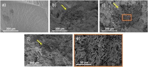
To gain further insight on the morphology of the composites and a better understanding of their mechanical properties, SEM analyses of the fracture surface of the same composites studied by XCT are presented in . In all cases, a slightly rough fracture surface is observed, characteristic of poorly ductile materials, as seen in the tensile curves of . SEM images show the presence of the cork particles on all of these surfaces, proving that they participate in the fracture mechanism. As previously mentioned, the cork particles have not been treated with any surface modification to make them compatible with ASA, so they act as potential crack initiators, causing a more brittle fracture of the composites than in the case of pure ASA. Furthermore, it seems to be a correlation between the amount and magnitude of the cork particles and the material resistance. Higher concentrations or larger sizes of cork particles tend to make the composite more fragile, supporting the hypothesis that these cracks originate primarily at the interface between the cork particles and the ASA matrix. (b–d) also shows a decrease of the cork particle size and its cellular structure is observed in all the composites studied (ASA10FC, ASA10CC and ASA30FC), in agreement with the XCT results. Small differences can be observed by SEM between the different composites, however. Besides the expected fact that particles are bigger in ASA10CC than in ASA10FC, the cork particles in ASA30FC can be identified less clearly. The detail of the flattened cork particle of ASA10FC shown in (e) also illustrates that the cork particles does not actually breaks, but their cellular structure is crushed, presenting a wrinkled structure.
Figure 9. Fracture surface of the tensile testing specimens of (a) ASA; (b) ASA10FC; (c) ASA10CC; and (d) ASA30FC. Yellow arrows indicate the location of cork particles within the ASA matrix. The detail of the flattened cork structure in ASA10CC is shown in (e).
This crushing was not observed in the cork composite pellets, where the cork morphology is maintained after compounding in the extruder (see Figure S14). However, this has been previously reported by other authors for composites manufactured by compression moulding, injection moulding, or FFF, using cork amounts between 15 and 50 wt.% and different polymer matrices [Citation10,Citation16,Citation41]. In these cases, the particle size used was always above 0.5 mm. Conversely, other works report a decrease in density proportional to the amount of cork used and negligible crushing of the cork particles when the particle size is below 400 µm [Citation22,Citation43]. Generally, the particle size has a key role in the processing of cork composites, since larger particles are more difficult to integrate into the polymer matrix, leading to manufactured parts with undesired porosity and increased surface defects [Citation18].
The presence of cork also reduces the mechanical properties of the polymer matrix, regardless of the polymer used and the manufacturing process. For instance, Magalhaes et al. [Citation42] compared the influence of cork particles in PLA composites prepared by injection moulding and FFF, finding that the presence of cork similarly decreased Young’s modulus and tensile strength in both cases. This effect is also observed by other authors when HDPE, polyhydroxybutyrate-co-hydroxyvalerate (PHBV), or epoxy resins are used [Citation16,Citation41,Citation44]. In our study, Young’s modulus and tensile strength values ranged from 1100 to 1300 MPa and 20–29 MPa, respectively, for 10–30 wt.% cork composites. In contrast, our previous work reported Young’s modulus and tensile strength of 900 and 19 MPa, respectively, for 5 wt.% cork composites prepared by FFF [Citation22]. This improvement may be attributed to the use of FGF-LFAM technology, which employs a nozzle with a larger diameter that deposits more material, favouring a more homogeneous distribution of the cork particles, especially those of larger size. This can minimise cork agglomeration and reduce their tendency to act as crack initiators. However, other studies show that the mechanical properties of cork composites (either injected or printed) can be enhanced using polymers grafted with maleic acid moieties (e.g. PE-g-MA or PLA-g-MA). Although the polymer matrix used in these cases was not ASA, these strategies could be considered in future work to further improve the mechanical properties of these composites, especially for XZ-printed specimens [Citation42,Citation45].
A brief environmental impact analysis was conducted by evaluating the carbon footprint of the materials used in this study. illustrates the estimated reduction in the carbon footprint of the composites compared to pure ASA. This analysis includes the CO2 emissions generated during the synthesis and transport of ASA and cork waste, as well as during the processing of the materials (including the compounding in the twin-screw extruder, which is not considered for pure ASA) and printing by FGF.
Figure 10. Estimation of (a) the contribution of the material synthesis, manufacturing and transport to the carbon footprint for each of the materials studied in this work and (b) the overall carbon footprint reduction of the cork composites compared to pure ASA.
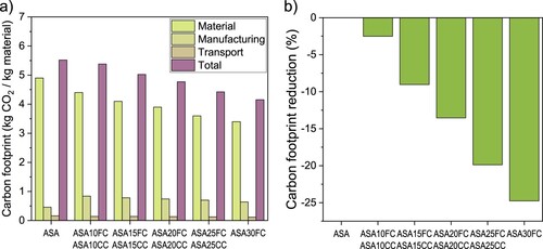
demonstrates that the carbon footprint per kilogram of material decreases gradually as the cork amount increases in the composites, reaching a reduction of 25% for ASA30FC. This reduction is primarily attributed to the decreased ASA content in the composites. Although an extra compounding step is required to produce the composites, the study shows that this does not result in a higher overall carbon footprint compared to pure ASA for any of the composites. Additionally, a small contribution comes from transportation, as the cork waste is sourced locally. No differences were found between FC and CC composites with the same amount of cork, since the particle size did not have an impact on the carbon footprint. Thus, developing these composites by valorising locally sourced cork waste presents a promising, more sustainable alternative to fossil fuel-derived plastics like ASA, especially those with high cork powder content.
Finally, a luminaire element is designed to valorise these materials. The luminaire was chosen as a product that will be subjected to a tensile stress due to its own weight when hung from the ceiling. ASA25CC was chosen as the material to print this design as it is the composite with the highest amount of CC that can be printed properly. The presence of CC will confer the luminaire with a more organic aesthetic than pure ASA, enhanced by the presence of the CC, visible to the naked eye. Moreover, from an industrial point of view, the possibility of using CC facilitates the up-scale of a possible production, facilitating the sieving of the initial cork waste. The inspiration for the development of this luminaire is drawn from the aesthetics of bird nests and huts made of materials such as straw and clay (see top-left corner of ), following a biomimetic process design. These designs are identified by a characteristic brown colour and a somewhat disordered and irregular lamellar structure typical of natural materials. This effect will be achieved by the combination of using cork composites and modifying the trajectory of each of the printing layers by employing different software designs.
Figure 11. The full design process divided into four blocks, (a) surface generation with the natural references; (b) surface contouring; (c) texturing contours with an attractor point and (d) closing surface. All modelled in Grasshopper.
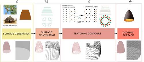
In our case, the plugin Grasshopper from the software Rhinoceros was used. This programme allows to create complex shapes and geometries using different connections between components, through algorithms. To achieve the bird nest aesthetic proposed, each of the curves that make up the printing layers of the piece were modified. An illustrated scheme together with the code divided into four working blocks are shown in . (a) shows a first block where the initial untextured surface of the luminaire is generated. (b) illustrates the following block, where the surface is subdivided in different layers, correlated with the layer height of the 3D printer. The next block, shown in (c), depicts how these layers are divided into points to modify the surface. In this block, a method based on the Attractor Point Function is used to generate a defined texture [Citation46]. This function consists of a series of blocks of operations that allows modifying the distance of the points of each layer with respect to a defined attractor point. The closer the points are to this attractor point, the more they will move from their original position. Therefore, a new layer is generated where some of those points are moved. This controlled movement of the points modifies the shape of the layer, which will no longer be circular, but with some protuberances. These protuberances will create small overhangs of the printing bead, creating a texture along the surface. Finally, (d) shows the block where the surface is closed to obtain a solid in Rhinoceros that can be exported as a STL format. This STL file is encoded so that the Simplify3D software of the FGF printer can recognise it, stablishing a layer height value equal to the one used in the generation of the contours of the Grasshopper code. This allows obtaining precisely the expected texture when slicing the design. It should be noted that this code can be used for the design of any type of products, where a partially or fully textured surface is desired. It would only be necessary to adjust the variable parameters that follow the specific design requirements and consider its manufacture. The fully-detailed Grasshopper code is shown in the Figures S15–S18.
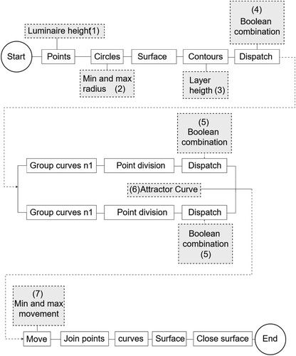
The flow of the code that generates the complete product in Grasshopper is shown in . The parameters that are required to shape the geometry of the design are framed in a grey rectangle (inputs): The height of the luminaire (1) and minimum and maximum radii (2) depend on the available printing volume and design requirements. The layer height (3) can also be tuned depending on the printer to be used. In this case, a layer height of 1.5 mm, valid for our ME-LFAM printer was set but this could be varied for benchtop FFF printers, or even vat photopolymerisation printers with micron-sized resolution. The layers of the luminaire will follow a repeating pattern (4), where only some layers are modified. This is customisable depending on the desired aesthetics. Then, the pattern of the dots of each layer is also defined in (5). The attractor curve (6) is defined as a function that generates modifications in the texture previously defined in (5). This is because the curve will act as an attractor of the points that move from the circular trajectory. Finally, the minimum and maximum distance that the points will move in the XY plane (parallel to the printing platform), creating the formation of the protuberances, is defined in (7).
Figure 12. The flow of variables and operations of the Grasshopper code. The input parameters are shown in a grey rectangle.
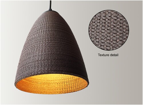
After creating the STL file, a bead width value (3.5 mm in our case) was also defined when selecting the printing conditions in order to increase the interlayer surface between two consecutive printed layers. This value generated small protrusions or overhangs while the prototype was being printed. In this way, a larger bead width allows part of the bead to be clamped on the previous one, avoiding overhangs and ensuring a correct printing. A digital photograph of the 3D-printed luminaire finished product is shown in . The design is able to withstand its own weight without delaminating and resist the subtle temperature variations that may arise from the light bulb. The detail of the texture shown in the proves that the combination of a cork-based material together with the use of new software design strategy allows the successful development of a product with a well-defined, bioinspired surface in the frame of biomimetics.
Figure 13. Image of the final product and detail of the texture.
4. Conclusions
In this work, we have developed a series of cork-based composites with contents from 10 to 30 wt.% cork using particles of sizes ranging from 0.4 to 1.8 mm, significantly larger than those typically reported in the literature. These composites were suitable for LFAM technologies, in particular by ME. The influence of cork size and concentration in the physical (i.e. colour and density) and mechanical properties was assessed. It was observed that the presence of cork did not decrease the density of the material, as expected. XCT and SEM analyses revealed that the cork morphology is altered during the processing, obtaining crushed particles embedded in the ASA matrix. The mechanical properties of the cork composites decreased with respect to those of pure ASA, as expected. However, it was observed that an increase from 10 to 30 wt.% of either FC or CC did not lead to a significant decrease in the mechanical properties. In particular, all the cork composites studied in this work presented Young’s modulus values between 1130 and 1360 MPa, tensile strength values between 20.2 and 28.9 MPa and elongation at break values between 2.5 and 3.0% for the XY specimens. These results are higher than those previously reported by other authors and us, even with lower cork contents. Therefore, the incorporation of high amounts of cork (10-30 wt.%) allows reducing the use of ASA (a fossil fuel-derived plastic) and makes it possible to take advantage of agro-waste that is currently incinerated, obtaining a new, more sustainable material. This is quantified through a carbon footprint analysis, which reveals that the carbon footprint of ASA can be reduced to 25% when using ASA30FC composites.
We also emphasise the potential of integrating parametric design software with AM technologies to model and customise final products according to user needs using the cork composites previously developed. This concept was exemplified in the biomimetic design of a luminaire inspired by bird nests. This approach significantly reduces material waste by leveraging AM technologies and valorising cork waste and enhancing the sustainability of the developed materials and designs. The inclusion of cork modifies the surface roughness and colour of the luminaire, imparting a brown hue and a more textured surface, resulting in a finish that resembles natural materials.
To the best of our knowledge, this is the first work to present the use of LFAM technologies for manufacturing cork composites. LFAM technologies are particularly appealing for industrial applications due to their higher deposition rates, which enable the production of the same object in a significantly shorter amount of time. Future research will focus on a more in-depth analysis of the sustainability of these materials, as well as the investigation of compounding cork waste with other materials. This includes exploring bio-based plastics and coupling agents to enhance the mechanical properties of the composites.
Supplemental Material
Download Zip (1.8 MB)Acknowledgements
The first part of this work was funded by the ADICORK project, through a collaboration agreement between Junta de Andalucía (Ministry of Agriculture, Livestock, Fisheries and Sustainable Development) and the University of Cádiz (research group INNANOMAT, ref. TEP-946). This agreement has been funded by UE. The second part of this work was funded by FUTURECORK project (ref. BF022). FUTURECORK is supported by the Biodiversity Foundation of the Ministerio para la Transición Ecológica y el Reto Demográfico (MITECO) within the framework of the Recovery, Transformation and Resilience Plan (PRTR), funded by the European Union – NextGenerationEU. PBP acknowledges the Ministry of Science, Innovation and Universities for the FPU predoctoral contract (FPU21/01402). SEM measurements were carried out at the DME-SC-ICyT-ELECMI-UCA.
Disclosure statement
No potential conflict of interest was reported by the author(s).
Data availability statement
The authors confirm that the data supporting the findings of this study are available within the article and the supporting information.
Additional information
Funding
References
- Li Y, Ren X, Zhu L, et al. Biomass 3D printing: principles, materials, post-processing and applications. Polymers (Basel). 2023;15:2692. doi:10.3390/polym15122692
- Moreno Nieto D, Molina SI. Large-format fused deposition additive manufacturing: a review. Rapid Prototyp J. 2020;26:793–799. doi:10.1108/RPJ-05-2018-0126
- Pignatelli F, Percoco G. An application- and market-oriented review on large format additive manufacturing, focusing on polymer pellet-based 3D printing. Prog Addit Manuf. 2022;7:1363–1377. doi:10.1007/s40964-022-00309-3
- Rajvanshi J, Sogani M, Kumar A, et al. Perceiving biobased plastics as an alternative and innovative solution to combat plastic pollution for a circular economy. Sci Total Environ. 2023;874:162441. doi:10.1016/j.scitotenv.2023.162441
- Romani A, Levi M, Pearce JM. Recycled polycarbonate and polycarbonate/acrylonitrile butadiene styrene feedstocks for circular economy product applications with fused granular fabrication-based additive manufacturing. Sustain Mater Technol. 2023;38:e00730. doi:10.1016/j.susmat.2023.e00730
- Moreno Nieto D, Casal López V, Molina SI. Large-format polymeric pellet-based additive manufacturing for the naval industry. Addit Manuf. 2018;23:79–85. doi:10.1016/j.addma.2018.07.012
- Nieto DM, Pintos PB, Sánchez DM, et al. Large format additive manufacturing in furniture design with novel cork based polymeric materials. In: Francisco Cavas-Martínez, Manuel D. Marín Granados, Ramón Mirálbes Buil and Oscar D. de-Cózar-Macías, editors. Advances in design engineering III. Cham: Springer International Publishing; 2023. p. 477–489.
- Zheng J, Suh S. Strategies to reduce the global carbon footprint of plastics. Nat Clim Chang. 2019;9:374–378. doi:10.1038/s41558-019-0459-z
- Rahman AM, Rahman TT, Pei Z, et al. Additive manufacturing using agriculturally derived biowastes: a systematic literature review. Bioengineering. 2023;10:845. doi:10.3390/bioengineering10070845
- Fernandes EM, Correlo VM, Mano JF, et al. Novel cork–polymer composites reinforced with short natural coconut fibres: effect of fibre loading and coupling agent addition. Compos Sci Technol. 2013;78:56–62. doi:10.1016/j.compscitech.2013.01.021
- Camarero JJ, Sánchez-Miranda Á, Colangelo M, et al. Climatic drivers of cork growth depend on site aridity. Sci Total Environ. 2024;912:169574. doi:10.1016/j.scitotenv.2023.169574
- Mestre A, Vogtlander J. Eco-efficient value creation of cork products: an LCA-based method for design intervention. J Clean Prod. 2013;57:101–114. doi:10.1016/j.jclepro.2013.04.023
- Ramos T, Matos AM, Sousa-Coutinho J. Strength and durability of mortar using cork waste ash as cement replacement. Mater Res. 2014;17:893–907. doi:10.1590/S1516-14392014005000092
- Atanes E, Nieto-Márquez A, Cambra A, et al. Adsorption of SO2 onto waste cork powder-derived activated carbons. Chem Eng J. 2012;211–212:60–67. doi:10.1016/j.cej.2012.09.043
- Novais RM, Senff L, Carvalheiras J, et al. Sustainable and efficient cork - inorganic polymer composites: An innovative and eco-friendly approach to produce ultra-lightweight and low thermal conductivity materials. Cem Concr Compos. 2019;97:107–117. doi:10.1016/j.cemconcomp.2018.12.024
- Fernandes EM, Correlo VM, Mano JF, et al. Cork–polymer biocomposites: mechanical, structural and thermal properties. Mater Des. 2015;82:282–289. doi:10.1016/j.matdes.2015.05.040
- Niknejad A, Moradi A. A novel solid cylindrical composite material made of agglomerated cork inserts and silicone rubber resin during the flattening process. Int J Mech Sci. 2016;115–116:105–122. doi:10.1016/j.ijmecsci.2016.06.007
- Martins CI, Gil V. Processing–structure–properties of cork polymer composites. Front Mater. 2020;7:297. https://www.frontiersin.org/article/10.3389fmats.2020.00297
- Romero-Ocaña I, Molina SI. Cork photocurable resin composite for stereolithography (SLA): influence of cork particle size on mechanical and thermal properties. Addit Manuf. 2022;51:102586. doi:10.1016/j.addma.2021.102586
- Gama N, Ferreira A, Evtuguin D, et al. Modified cork/SEBS composites for 3D printed elastomers. Polym Adv Technol. 2022;33:1881–1891. doi:10.1002/pat.5644
- Alvarez Gómez M, Moreno Nieto D, Moreno Sánchez D, et al. Additive manufacturing of thermoplastic polyurethane-cork composites for material extrusion technologies. Polymers (Basel). 2023;15:3291. doi:10.3390/polym15153291
- de León AS, Núñez-Gálvez F, Moreno-Sánchez D, et al. Polymer composites with cork particles functionalized by surface polymerization for fused deposition modeling. ACS Appl Polym Mater. 2022;4:1225–1233. doi:10.1021/acsapm.1c01632
- TDS SMARTFIL CORK, Accessed: July 10, 2024. [Online]. Available: https://www.smartmaterials3d.com/en/cork.
- Klyusov N, Garin N, Usenyuk-Kravchuk S, et al. A biomorphic approach to designing special-purpose vehicles for Arctic conditions. Biomimetics. 2023;8:360. doi:10.3390/biomimetics8040360
- Li Y, Zhao Y, Chi Y, et al. Shape-morphing materials and structures for energy-efficient building envelopes. Mater Today Energy. 2021;22:100874. doi:10.1016/j.mtener.2021.100874
- Kumar DS, Purani K, Viswanathan SA. The indirect experience of nature: biomorphic design forms in servicescapes. J Serv Mark. 2020;34:847–867. doi:10.1108/JSM-10-2019-0418
- Tao J, Tahmasebi P, Kader MA, et al. Wood biomimetics: capturing and simulating the mesoscale complexity of willow using cross-correlation reconstruction algorithm and 3D printing. Mater Des. 2023;228:111812. doi:10.1016/j.matdes.2023.111812
- Ufodike CO, Ahmed MF, Dolzyk G. Additively manufactured biomorphic cellular structures inspired by wood microstructure. J Mech Behav Biomed Mater. 2021;123:104729. doi:10.1016/j.jmbbm.2021.104729
- F. Pérez-Arribas, parametric generation of small ship hulls with CAD software. J Mar Sci Eng. 2023;11:976. doi:10.3390/jmse11050976
- Efstathiadis A, Symeonidou I, Tsongas K, et al. Parametric design and mechanical characterization of 3D-printed PLA composite biomimetic voronoi lattices inspired by the stereom of sea urchins. J Compos Sci. 2023;7:3. doi:10.3390/jcs7010003
- Gokmen S. Stripped and layered fabrication of minimal surface tectonics using parametric algorithms. Curved Layered Struct. 2023;10:20220210. doi:10.1515/cls-2022-0210
- Costantino D, Grimaldi A, Pepe M. 3D modelling of buildings and urban areas using grasshopper and Rhinocersos. Geographia Technica. 2022;17:167–176. doi:10.21163/GT_2022.171.13
- García-Dominguez A, Claver J, Sebastián MA. Optimization methodology for additive manufacturing of customized parts by fused deposition modeling (FDM). application to a shoe heel. Polymers (Basel). 2020;12:2119. doi:10.3390/POLYM12092119
- Burgos Pintos P, Sanz de León A, Molina SI. Large format additive manufacturing of polyethylene terephthalate (PET) by material extrusion. Addit Manuf. 2024;79:103908. doi:10.1016/j.addma.2023.103908
- Duty C, Ajinjeru C, Kishore V, et al. A viscoelastic model for extrusion-based 3D printing of polymers what makes a material printable ? J Manuf Process. 2017;Submitted:526–537. doi:10.1016/j.jmapro.2018.08.008
- Ajinjeru C, Kishore V, Liu P, et al. Determination of melt processing conditions for high performance amorphous thermoplastics for large format additive manufacturing. Addit Manuf. 2018;21:125–132. doi:10.1016/j.addma.2018.03.004
- Northcutt LA, Orski SV, Migler KB, et al. Effect of processing conditions on crystallization kinetics during materials extrusion additive manufacturing. Polymer. 2018;154:182–187. doi:10.1016/j.polymer.2018.09.018
- Burgos Pintos P, Moreno Sánchez D, Delgado FJ, et al. Influence of the carbon fiber length distribution in polymer matrix composites for large format additive manufacturing via fused granular fabrication. Polymers (Basel). 2024;16:60. doi:10.3390/polym16010060
- Yeole P, Hassen AA, Kim S, et al. Mechanical characterization of high-temperature carbon fiber-polyphenylene sulfide composites for large area extrusion deposition additive manufacturing. Addit Manuf. 2020;34:101255. doi:10.1016/j.addma.2020.101255
- Copenhaver K, Smith T, Armstrong K, et al. Recyclability of additively manufactured bio-based composites. Compos B Eng. 2023;255:110617. doi:10.1016/j.compositesb.2023.110617
- Brites F, Malça C, Gaspar F, et al. Cork plastic composite optimization for 3D printing applications. Procedia Manuf. 2017;12:156–165. doi:10.1016/j.promfg.2017.08.020
- Magalhães da Silva SP, Antunes T, Costa MEV, et al. Cork-like filaments for additive manufacturing. Addit Manuf. 2020;34:101229. doi:10.1016/j.addma.2020.101229
- Daver F, Lee KPM, Brandt M, et al. Cork–PLA composite filaments for fused deposition modelling. Compos Sci Technol. 2018;168:230–237. doi:10.1016/j.compscitech.2018.10.008
- Nóvoa PJRO, Ribeiro MCS, Ferreira AJM, et al. Mechanical characterization of lightweight polymer mortar modified with cork granulates. Compos Sci Technol. 2004;64:2197–2205. doi:10.1016/j.compscitech.2004.03.006
- Dairi B, Bellili N, Hamour N, et al. Cork waste valorization as reinforcement in high-density polyethylene matrix. Mater Today Proc. 2022;53:117–122. doi:10.1016/j.matpr.2021.12.420
- Tedeschi A, Wirz F. Aad algorithms-aided design: parametric strategies using grasshopper. Brienza: Le Penseur; 2015.