Abstract
Background and purpose Polyethylene is commonly employed for bearings in acetabular cups used in hip replacements. Assessment of in vivo wear is important for evaluation and monitoring of wear in individual patients, as well as in different implant designs. Polyethylene wear is quantified by comparisons of radiographic measurements made on sequential pelvic radiographs. Variations in pelvic orientation and variation in direction of wear may cause underestimation of polyethylene wear measurements. The purpose of this study was to quantify these effects on 2-dimensional measurements of polyethylene wear.
Methods A computer program designed to simulate radiographs was employed to generate virtual radiographs of a virtual pelvis with a total hip replacement. Effects caused by variation in pelvic spatial orientation and variations in wear direction on wear measurements were analyzed separately. A Monte Carlo computational algorithm was employed to describe the combined effects of these two factors.
Results Variation in pelvic orientation induced a mean underestimation of wear of 0.4% (0–2.6). Variation in direction of wear introduced a mean underestimation of 8.5% (0–42). A mean underestimation of wear of 9% (0–99) was found when varying both pelvic orientation and direction of wear simultaneously.
Interpretation Errors caused by variations in pelvic orientation and wear direction are likely to be small compared to other sources of error when performing polyethylene wear measurements in acetabular components.
Polyethylene is commonly used as a bearing in acetabular components in hip replacements. Polyethylene wear particles induce osteolysis, which contributes to failure of total hip replacements (Maloney et al. Citation1993, Dowd et al. Citation2000, Barrack et al. Citation2002, Orishimo et al. Citation2004). Hopefully, new generations of “hard-on-hard” combinations may reduce wear-related problems (Shetty and Villar Citation2006); however, polyethylene is still commonly used and exact determination of polyethylene wear is therefore important (Martell and Berdia Citation1997). Measurements of polyethylene wear in acetabular components in situ are mainly obtained by comparisons of radiographic measurements from pairs of sequential radiographs, the duo-radiographic method (Charnley and Halley Citation1975). Typically, measurements made on early postoperative radiographs are compared with radiographs from the latest follow-up. Wear is described as displacement of the prosthetic femoral head relative to the acetabular component, in terms of angles and distances. The main direction of wear in respect to to the radiographic film plane influences the measurements of wear distance. When radiographs are obtained with the main wear direction oblique to the plane of the film, the projection of the wear length is foreshortened.
By radiography, 3-dimensional objects are transformed into 2-dimensional pictures. The spatial orientation of the object is one among several factors affecting picture formation (Katz Citation1979, Siebenrock et al. Citation2003, Tannast et al. Citation2005). Consequently, both pelvic orientation and wear direction in the acetabular cup contribute to radiographic underestimation of the wear distance measured.
We quantified the effects caused by variations in pelvic orientation and acetabular wear direction on 2-dimensional radiographic polyethylene wear measurements of acetabular cup bearings.
Material and methods
Acetabular wear can be measured radiographically by 2-dimensional and 3-dimensional techniques (AP radiographs only, and AP and lateral radiographs, respectively) (Devane et al. Citation1995). 3- dimensional techniques give a higher wear rate in 5% of the hips analyzed (Sychterz et al. Citation1999). 2- dimensional techniques are generally considered to have sufficient accuracy for routine clinical assessment of wear (Hui et al. Citation2003).
Foss et al. (Citation2007c) quantified pelvic rotational differences between sequential radiographs in clinical material by use of a new method named the rotation ratios method (RRM). The RRM describes altered pelvic orientation between pairs of sequential standard AP pelvic radiographs obtained from the same pelvis (Foss et al. Citation2007a, Citationb, Citationc). Two ratios are calculated, based on marking of 5 reference points on standard pelvic AP radiographs. Pelvic rotations around two axes can then be described based on the differences between these two ratios on the two radiographs analyzed using a set of formulae.
The clinical material consisted of 262 standard supine pelvic radiographs in 46 patients with total hip replacement (THR). A minimum of 3 radiographs (mean 5.7 (3-10)) for each of the patients were analyzed. The 97.5 percentiles of rotational differences between pairs of radiographs were 3.4 degrees of rotation around the vertical axes and 9.7 degrees of rotation around the transversal axes. As a consequence, the cutoff points of pelvic orientations selected in the present study were based on these results by including pelvic movements inside ± 3.4 degrees of vertical rotation and ± 9.7 degrees of transversal rotation.
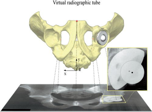
A computer program was designed for simulation of radiographs, representing a virtual radiographic laboratory in which all relevant variables can be defined mathematically (Foss et al. Citation2007b). Virtual rigid-point objects are defined in a 3-axial (x, y, and z) orthogonal coordinate system. The x-axis is transversal, the y-axis is anteroposterior, and the z-axis is longitudinal. The virtual object’s spatial orientation, the radiographic focusing, the focus-film distance, and the object-.lm distance are defined separately and virtual radiographs are made. A virtual pelvis with a THR was “mounted” into this radiographic laboratory (). The virtual pelvis was based on 3-dimensional measurements from a pelvic model as described previously (Foss et al. Citation2007a). Pelvic rotations around the x-axis were termed transversal rotations and those around the z-axis were termed vertical rotations. Acetabular wear directions were altered in the coronal plane (the x-z plane) and the sagittal plane (the y-z plane). The center of the acetabular component was chosen as the acetabular reference point, as used in computer-aided measuring programs (Sychterz et al. Citation1997, Martell and Berdia Citation1997) and displacements of the caput center were related to the center of the acetabular cup. The distance between the center of the femoral head and the center of the acetabular cup was set to be 1.0 mm, representing virtual polyethylene wear. Yamaguchi et al. (Citation1999b) have reported the main direction of polyethylene wear in vivo to be mean 8.1 (SD 24) degrees laterally in the coronal plane and 4.1 (SD 24) degrees anteriorly in the sagittal plane. As a consequence, the direction of virtual wear in the present study was initially directed 8.1 degrees laterally and 4.1 degrees anteriorly, and the effects of varying the direction of wear inside the ± 2 SD intervals were examined.
Figure 1. Virtual pelvic radiographs were made using computer simulation. The virtual pelvis was represented by 5 points: the most caudal part of the two teardrops, the most distal part of the two sacro-iliac joints, and the midpoint of the most cranial part of the pelvic symphysis. The virtual total hip replacement was represented by the center of the acetabular cup (marked with a cross-hair) and the center of the femoral head (marked with a circle). The projected distance between these two represents both polyethylene wear and the projected wear direction. Virtual pelvic rotations were performed around the x- and the z-axes, and wear directions were altered in the coronal plane and the sagittal plane. The effects on the virtual wear measurements were then quantified.
The pelvic start orientation was 5 degrees of reclination, defined as the angle between the plane through the anterior pubic tubercles and the anterior superior iliac spines (McKibbin plane) and the coronal plane. This orientation represents an average pelvic tilt in adults in supine position (Anda et al. Citation1990). Focus-to-.lm distance was set to 118 cm. The central beam was simulated as being directed perpendicular to the virtual radiographic film and focused on the cranial midpoint of the pubic symphysis, as commonly used in radiographic evaluation of the hip. First, the direction of wear was kept constant (8.1 degrees lateral and 4.1 degrees anterior) while virtual pelvic rotations were made in order to investigate the effects caused by pelvic rotations alone. The virtual pelvis was simulated as being rotated in series with incremental steps of 2.0 degrees from –30 to +30 degrees around the vertical axis with incremental steps of 2.0 degrees around the transversal axes inside the –30-degree to +30-degree interval. By making a virtual radiograph in each position, 961 virtual images were produced. The virtual projections of the distance between the center of the femoral head and the center of the acetabular cup were quantified on each virtual radiograph.
Secondly, the pelvic orientation was kept constant (in its start orientation) while the direction of wear was varied inside the ± 2 SD intervals found by Yamaguchi et al. (1999c). The wear direction was altered in incremental steps of 2.0 degrees inside the –41-degree to +57-degree interval in the coronal plane and –44-degree to +52-degree interval in the sagittal plane, with 2,450 virtual radiographs made.
A Monte Carlo method was employed to further describe the effects of variations in pelvic orientation and direction of wear. 4 normally distributed data series were generated (Labview; National Instruments, Austin, TX) based on the clinical data for pelvic rotation and wear direction presented earlier. Pelvic orientations were defined within ± 9.7 degree intervals around the transversal axis and within ± 3.4 degree intervals around the vertical axis. Wear direction in the coronal plane (inside the 41-degree to +57-degree intervals) and in the sagittal plane (inside the −44-degree to +52-degree intervals) were also defined. Data from these 4 series were used as input data into the Monte Carlo algorithm representing pelvic orientation related to the transversal and vertical axes and wear directions (related to the coronal and sagittal planes).
One Monte Carlo analysis was first performed, including 100,000 pelvic orientations, while the wear direction was kept constant (8.1 degrees laterally and 4.1 degrees anteriorly). A second analysis was performed, including 100,000 of wear directions, while keeping the pelvic orientation constant (5 degrees of reclination). A third analysis was finally performed, in which the 100,000 pelvic orientations and the 100,000 wear directions were varied simultaneously.
Results
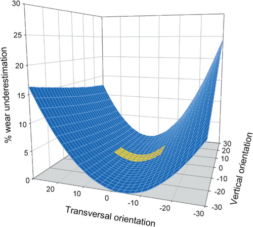
The correlation between virtual pelvic rotations and the percentage of underestimation of polyethylene wear is presented in . This 3-dimensional graph describes the effects seen within the ranges of virtual pelvic rotations that were initially selected. The yellow, lower part of the graph describes the effects found when the ranges of rotation were limited to those found clinically. Simultaneous rotations around the two axes may enhance, or to some extent eliminate, the effects on underestimation of wear. A maximum of 2.6% underestimation of wear within pelvic rotational ranges was found clinically. Only a mean of 0.4% wear underestimation was found when the direction of wear was kept constant and only the pelvic orientation was varied.
Figure 2. The correlation between the orientation of the virtual pelvis and the degree of underestimation of wear. The ranges of pelvic orientation were initially selected arbitrarily to be larger than those found in clinical settings. The yellow area represents variations in pelvic orientation found in clinical material, and a maximum of 2.6% of underestimation of wear was found.
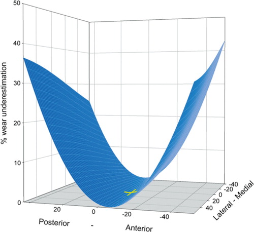
The percentages of wear underestimation related to direction of wear are presented in . A maximum of 42% and a mean of 8.5% underestimation of wear were found when varying the wear direction only. Variation in direction of wear in the sagittal plane had a large influence on underestimation of wear, resulting in oblique angles between the direction of wear and the radiographic film plane. In contrast, variations in the coronal plane had only a small effect on underestimation of wear since the parallelism between the direction of wear and the film plane remains constant.
Figure 3. A maximum of 42% underestimation of wear was found when the wear directions were altered in the coronal plane (lateral-medial) and the sagittal plane (anteriorposterior) within ranges found clinically. The yellow crosshair marks the most common direction of wear described by Yamaguchi et al. (date) (8.1 degrees laterally and 4.1 degrees anteriorly). Variations in direction of wear in the coronal plane hade little effect on wear measurements since the parallelism between the direction of wear and the film plane remains unaltered.
A mean of 8.9% (0–99) wear underestimation was found when varying both pelvic orientation and wear direction simultaneously (2.5 percentile: 0.6; 97.5 percentile: 44.1).
Discussion
In vivo measurements of polyethylene wear in acetabular components are mainly based on comparisons of measurements from sequential pelvic radiographs. Polyethylene is radiolucent, which makes direct radiographic measurement difficult. Consequently, an indirect approach is used whereby the migration of the femoral prosthetic head relative to the acetabular component is quantified. Several assumptions must be made in such a procedure, which can introduce potential sources of error.
The prosthetic head must be in contact (fully reduced) with the polyethylene inside the acetabular component when radiographs are taken. This may not be so when compression forces through the hip joint are small, e.g. radiography of patients in supine position. Several studies have investigated the influence of compression forces on polyethylene measurements (Smith et al. Citation1999, Martell et al. Citation2000, Moore et al. Citation2000, Bragdon et al. Citation2006, von Schewelov et al. Citation2006). Radiographs obtained in both supine and erect position, and also radiographs obtained in supine position with and without a small leg raise, were compared. The results were not conclusive. Small differences were found that were of little clinical importance, but there was a statistically significant difference of 0.5 mm linear wear. The prosthetic head may not be fully reduced shortly after hip replacement; consequently, one should avoid using radiographs taken immediately postoperatively as baseline in wear measurements (Martell et al. Citation2000).
Combinations of metal backings and polyethylene inserts are often selected in cementless acetabular components. Wear on the back-side of the polyethylene insert may occur (back-side wear), together with wear of the articular surface (Yamaguchi et al. Citation1999a, Wasielewski et al. Citation2005). Such additional wear remains undetected by techniques of wear measurement that are currently available. An investigation into the effect of radiographic quality has shown that suboptimal radiographs reduce the accuracy of wear measurements (Sychterz et al. Citation2001).
The effect of the radiographic focusing on polyethylene wear measurements has been investigated (Collier et al. Citation2003). Radiographs of a phantom with zero wear were obtained with different focusing along the cephalo-caudal axis. Both 2-dimensional and 3-dimensional wear analyses were performed and the polyethylene wear measurements were expected to be zero. In some cases, a false impression of wear was detected—exceeding the amount of wear expected to be present 5 years after the implantation.
Investigations of retrieved acetabular cups have demonstrated multiple directions of wear in approximately 30% of the cups (Akisue et al. Citation1999, Yamaguchi et al. Citation1999b). The volumetric wear will thus be underestimated by radiographic measurements, assuming a single direction of wear only.
Wear can be described in terms of linear wear and volumetric wear. 2-dimensional analysis mainly describes linear wear (the distance of motion of the femoral head relative to the acetabular cup). Several conversion formulae can be used to calculate the volumetric wear based on linear measurements (Kabo et al. Citation1993, Charnley et al. Citation1969, Derbyshire Citation1998). They all include assumption of a certain amount of cylindrical wear but some also include other factors based on different complexities of the polyethylene liner geometry and direction of wear. The percentage of underestimation of wear caused by variations in pelvic orientation and direction of wear will be approximately the same in both linear and volumetric wear rates, as long as most of the wear zone lies within the cylindrical part of the polyethylene liner.
We used a virtual 1.0-mm wear vector during the simulation, but the rate of underestimation of wear will be unaffected by the magnitude of wear as long the results are presented as percentages.
Initially, we performed simulations of pelvic radiographs within a large arbitrary range of pelvic orientations to demonstrate the principle of the effect on wear measurements. Changes in pelvic orientation found clinically were relatively small, however, resulting in only small effects on wear measurements. One shortcoming of our study is the limited amount of data available related to variations in pelvic orientation and wear direction found clinically. To our knowledge, only one publication has described pelvic rotations found clinically (Foss et al. Citation2007c), and one other described the direction of wear in respect of pelvises (but not regarding acetabular cups only) (Yamaguchi et al. Citation1999b). The principles we describe are valid even if the ranges of pelvic movement or wear direction would be different from those we employed.
In conclusion, the underestimation of wear induced by variations in pelvic orientation and in main wear direction appears to be small compared to other sources of error when performing polyethylene wear measurements in acetabular components using 2-dimensional techniques on standard pelvic radiographs.
We wish to thank Dr B. Evans, Cambridge, UK for language correction and Prof. Stian Lydersen of the Norwegian University of Science and Technology (NTNU), Trondheim, Norway for his assistance with the statistical analysis.
No competing interests declared.
Contributions of authors
OAF and JK designed study, performed the data analysis, and wrote the manuscript. JK performed the computer programming and simulation. PB and SA were mainly involved in writing of the manuscript.
- Akisue T, Bauer T W, Yamaguchi M, Matejczyk M B, Stulberg B N, Wilde A H. Multidirectional deformation in fully congruent acetabular components. J Arthroplasty 1999; 14: 1011–8
- Anda S, Svenningsen S, Grontvedt T, Benum P. Pelvic inclination and spatial orientation of the acetabulum. A radiographic, computed tomographic and clinical investigation. Acta Radiol 1990; 31: 389–94
- Barrack R L, Castro F P, Szuszczewicz E S, Schmalzried T P. Analysis of retrieved uncemented porous-coated acetabular components in patients with and without pelvic osteolysis. Orthopedics 2002; 25: 1373–8
- Bragdon C R, Thanner J, Greene M E, Malchau H, Digas G, Harris W H, Karrholm J. Standing versus supine radiographs in RSA evaluation of femoral head penetration. Clin Orthop 2006, 448: 46–51
- Charnley J, Halley D K. Rate of Wear in Total Hip-Replacement. Clin Orthop 1975, 112: 170–9
- Charnley J, Kamangar A, Longfiel M D. Optimum Size of Prosthetic Heads in Relation to Wear of Plastic Sockets in Total Replacement of Hip. Med Biol Eng 1969; 7: 31–9
- Collier M B, Kraay M J, Rimnac C M, Goldberg V M. Evaluation of contemporary software methods used to quantify polyethylene wear after total hip arthroplasty. J Bone Joint Surg (Am) 2003; 85: 2410–8
- Derbyshire B. The estimation of acetabular cup wear volume from two-dimensional measurements: a comprehensive analysis. Proc Inst Mech Eng 1998; 212: 281–91
- Devane P A, Bourne R B, Rorabeck C H, Hardie R M, Horne J G. Measurement of polyethylene wear in metal-backed acetabular cup. 1.3-dimensional technique. Clin Orthop 1995, 319: 303–16
- Dowd J E, Sychterz C J, Young A M, Engh C A. Characterization of long-term femoral-head-penetration rates. Association with and prediction of osteolysis. J Bone Joint Surg (Am) 2000; 82: 1102–7
- Foss O A, Klaksvik J, Benum P, Anda S. Pelvic rotations: A pelvic phantom study. Acta Radiol 2007a; 48: 650–7
- Foss O A, Klaksvik J, Benum P, Anda S. The rotation ratios method: A method to describe altered pelvic orientation in sequential radiographs. Acta Radiol 2007b; 48: 1011–9
- Foss O A, Klaksvik J, Benum P, Anda S. Validation of the rotation ratios method. Acta Radiol 2007c; 48: 658–64
- Hui A J, McCalden F W, Martell J M, MacDonald S J, Bourne R B, Rorabeck C H. Validation of two and threedimensional radiographic techniques for measuring polyethylene wear after total hip arthroplasty. J Bone Joint Surg (Am) 2003; 85: 505–11
- Kabo J M, Gebhard J S, Loren G, Amstutz H C. In vivo wear of polyethylene acetabular components. J Bone Joint Surg (Br) 1993; 75: 254–8
- Katz J F. Precise Identification of radiographic acetabular landmarks. Clin Orthop 1979, 141: 166–8
- Maloney W J, Peters P, Engh C A, Chandler H. Severe osteolysis of the pelvis in association with acetabular replacement without cement. J Bone Joint Surg (Am) 1993; 75: 1627–35
- Martell J M, Berdia S. Determination of polyethylene wear in total hip replacements with use of digital radiographs. J Bone Joint Surg (Am) 1997; 79: 1635–41
- Martell J M, Leopold S S, Liu X. The effect of joint loading on acetabular wear measurement in total hip arthroplasty. J Arthroplasty 2000; 15: 512–8
- Moore K D, Barrack R L, Sychterz C J, Sawhney J, Yang A M, Engh C A. The effect of weight-bearing on the radiographic measurement of the position of the femoral head after total hip arthroplasty. J Bone Joint Surg (Am) 2000; 82: 62–9
- Orishimo K F, Claus A M, Sychterz C J. Relationship between polyethylene wear and osteolysis in hips with a second-generation porous-coated cementless cup. J Bone Joint Surg (Am) 2004; 86: 1095–9
- Shetty V D, Villar R N. Development and problems of metalon-metal hip arthroplasty. Proc Inst Mech Eng 2006; 220: 371–7
- Siebenrock K A, Kalbermatten D F, Ganz R. Effect of pelvic tilt on acetabular retroversion: A study of pelves from cadavers. Clin Orthop 2003, 407: 241–8
- Smith P N, Ling R S, Taylor R. The in.uence of weightbearing on the measurement of polyethylene wear in THA. J Bone Joint Surg (Br) 1999; 81: 259–65
- Sychterz C J, Engh C A, Shah N, Engh C A. Radiographic evaluation of penetration by the femoral head into the polyethylene liner over time. J Bone Joint Surg (Am) 1997; 79: 1040–6
- Sychterz C J, Yang A M, McAuley J P, Engh C A. Twodimensional versus three-dimensional radiographic measurements of polyethylene wear. Clin Orthop 1999, 365: 117–23
- Sychterz C J, Young A M, Engh C A. Effect of radiographic quality on computer-assisted head penetration measurements. Clin Orthop 2001, 386: 150–8
- Tannast M, Zheng G, Anderegg C, Burckhardt K, Langlotz F, Ganz R, Siebenrock K A. Tilt and rotation correction of acetabular version on pelvic radiographs. Clin Orthop 2005, 438: 182–90
- von Schewelov T, Onsten I, Markusson P, Carlsson A. Weight bearing radiographs are not necessary for measurement of polyethylene penetration in total hip prostheses: a radiostereometric study of 111 patients examined in weight-bearing and supine position. Acta Orthop 2006; 77: 104–8
- Wasielewski R C, Jacobs J J, Arthurs B, Rubash H E. The acetabular insert-metal backing interface. An additional source of polyethylene wear debris. J Arthroplasty 2005; 20: 914–22
- Yamaguchi M, Bauer T W, Hashimoto Y. Deformation of the acetabular polyethylene liner and the backside gap. J Arthroplasty 1999a; 14: 464–9
- Yamaguchi M, Hashimoto Y, Akisue T, Bauer T W. Polyethylene wear vector in vivo: A three-dimensional analysis using retrieved acetabular components and radiographs. J Orthop Res 1999b; 17: 695–702