
 ?Mathematical formulae have been encoded as MathML and are displayed in this HTML version using MathJax in order to improve their display. Uncheck the box to turn MathJax off. This feature requires Javascript. Click on a formula to zoom.
ABSTRACT
To enhance the water flux and salt rejection of reverse osmosis membranes, thin film nanocomposite reverse osmosis membranes were prepared by incorporating functionalised single-walled carbon nanotubes (SWNTs). The functionalised SWNTs were obtained by chemical process such as mixed acid oxidation and substitution reaction. The SWNTs were characterised by HRTEM, FTIR, TGA, Raman spectra, UV-Vis and XPS, etc. The surface morphology and structure of membrane were characterised by SEM and contact angle measurement, respectively. The results showed that carboxyl, acyl, amide and amine were successfully grafted on the tip and inner wall of the single-walled carbon nanotubes. The dispersity of the functionalised SWNTs in water was tested, indicating a good hydrophilic property. The polyamide/modified CNT nanocomposite reverse osmosis membrane was prepared. Compared with the bare polyamide membrane, the SWNT-polyamide thin film nanocomposite membranes showed higher property in hydrophilic surface and its water flux, as along with salt rejection, improved dramatically. The experimental results revealed that the modified SWNTs (especially those containing hydrophilic groups such as carboxyl groups and amino groups) well dispersed in the polyamide thin film layer, and hence improved the water permeation, and the salt rejection.
Abbreviation:
1. Introduction
Since CNTs was discovered by Iijima [Citation1] in 1991, it has become a viable candidate for a wide applications and has caused a worldwide interest such as extraordinary optical properties, electronics, thermal and mechanical properties [Citation2–10]. However, CNTs are easy to reunite and have bad water dispersion, since they are inherently insoluble in most organic and aqueous solvents, and poor chemically compatible with the polymer matrix due to the surface defects, the lack of reactive group, together with the strong Van der Waals’ force and huge specific surface area or high length-diameter ratio. These properties limit its application.
In order to improve the hydrophilicity and the dispersity of carbon nanotubes, a great many of researches such as oxidation with HNO3 [Citation11–13], or mixed acid H2SO4/HNO3 (1:1; 1:1.6; 3:1; 3:2, v/v) [Citation14–17] have been reported in recent years. It proved that acid oxidation could not only remove the amorphous carbon in the carbon nanotubes but improve the dispersity, concentration and the stability of CNTs in polar solvent. More importantly, it allowed the structure of CNTs for further modification. We wonder whether the more reagent are used, the better dispersion will be obtained. Kanbur teams [Citation14] have functionalised CNTs with different ratios of sulphuric and nitric acid. Result showed that modified CNTs had a stable dispersion and the conductive performance increased when the content of H2SO4, -SO3H increased. However, Richard Sawick et al. [Citation18] in the research of mesoporous cyclodextrin-silica nanocomposites for the removal of pesticides found that the ideal adsorption capacity did not follow the rule that the higher the concentration was, the more the binding sites were, but it was affected by their position and direction. There are other ways to improve the hydrophilicity and the dispersity of carbon nanotubes. Y. Hattori et al. [Citation19] used fluorinating grafted functional group on the inner wall of the carbon nanotubes. Other researches were conducted to silanize the carbon nanotubes [Citation17], to graft the polystyrene by radiation-induced method [Citation20], to graft alkyldiamines H2N(CH2)2nNH2 (n = 1–4) by condensation reaction [Citation21], or to graft benzoic acid by covalent bond [Citation22], which all improved the CNTs’ solubility in organic solvent and enhanced the adhesion strength between carbon nanotubes and substrate interface.
Researches have indicated that water could migrate through narrow CNT [Citation1,Citation23,Citation24] in high speed and almost be independent of the length of the CNTs [Citation25]. According to that, Lin Zhang et al. [Citation15] and Haiyang Zhao et al. [Citation26] synthesised the polyamide/MWNTs membrane. Compared with the raw polyamide composite membrane, the increase of the amount of MWNTs (contains hydrophilic group) in a membrane would enlarge the water flux, while the salt rejection remained relatively high (>90%) in spite of a slight decrease. Our research group have done a series of simulations on water flux and salt rejection of modified single-walled and multi-walled carbon nanotubes [Citation27,Citation28], The results showed that when certain number and type of functional group (-COOH, -CONH2 and -NH2) were added to the interior and/or on the tip of single-walled (10, 10)(1.356 nm) or (13, 13)(1.763 nm), 100% salt rejection could be obtained and high water flux (13 times of the traditional reverse osmosis membrane) be maintained. In view of that, a series of tip and inner modification of SWNTs (with 3.5 nm inner diameter) were directly conducted in this article and SWNTs were embedded throughout the polyamide thin film of an interfacial composite RO membrane for desalination. This built the foundation applicable to the separation of membrane preparation and further to the field of seawater desalination in the future.
This article modified the single-walled carbon nanotubes based on the mixed acid (sulphuric acid, nitric acid) oxidation method, and further converted carboxyl to amino to achieve water-soluble improvement of CNTs. At the same time, we prepared SWNT-polyamide nanocomposite membranes by interfacial polymerisation. The functionalised SWNTs were characterised by HRTEM, FTIR, XPS, TGA, Raman spectra, and Uv-vis. The SWNT-polyamide nanocomposite membrane were characterised by SEM, contact angle goniometer, and water flux and salt rejection evaluation.
2. Experiments
2.1. Materials and solvents
Single-walled carbon nanotubes (SWNTs) (purity >95%, diameter 3.5 nm, length 5–30 μm, Ash < 0.5 wt%, SSA > 450 m2/g, EC > 100 s/cm), sulphuric acid (95%−98%), nitric acid (65%−68%), pyridine (Py), dimethylformamide (DMF), thionyl chloride (SOCl2), ammonium carbonate ((NH4)2CO3), tetrahydrofuran(THF), methanol, sodium, bromine, PTFE membrane (diameter 50 mm, pore size 0.22 μm). Polysulfone (PSF) membranes, m-Phenylenediamine (MPD, 99%), trimesoyl chloride (TMC, 98%), n-Hexane (97%).
2.2. Preparation of functionalised SWNTs
Since SWNTs are generally seriously bundled, pristine SWNTs were immersed in 80 ml of concentrated H2SO4/HNO3 (3:1, v/v) solution at 60 °C and treated by stirring reflux for 4 h. The resulting solution was diluted by deionised water and vacuum-filtered in PTFE membrane until the pH of the filtrate turned to be neutral. The product (I) was dried in vacuum drying oven at 60 °C for 24 h.
The product (I) was stirred in an excess mixture solution of DMF and SOCl2 (1:9) at 85 °C for 30 h. The main purpose of this process is to convert the carboxylic acids into acyl chlorides. An excess of SOCl2 was removed by reduced pressure distillation. The product (II) was washed by THF and vacuum-filtered in PTFE membrane and then dried under vacuum at 60 °C for 24 h.
320 mg of Product (II) was added into 15,000 mg (NH4)2CO3 suspension which was dispersed in 50 ml DMF. Then 50 ml pyridine was added slowly into the reactor under continuous stirring at room temperature. Subsequently, the solution was treated by stirring reflux at 70 °C for 46 h. The product was obtained by PTFE membrane and washed with water and ethanol individually. Finally, the product (III) -amide SWNTs was dried in vacuum drying oven at 60 °C for 12 h.
To get amino SWNTs, about 1200 mg Na was immersed in 100 ml methanol, the resulting solution was mixed with 2 ml bromine and 260 mg product (III). The mixed solution was stirred at 70 °C for 24 h and then 1 ml Br2 were dropped in followed by another 24 h continuous stirring. The collected black solid was filtered and then washed with saturated sodium carbonate, water and ethanol separately. The solid product (IV) was dried at 60 °C for 12 h.
2.3. Characterisation of SWNTs
The morphology and the wall thickness of the samples were observed with High resolution Transmission Electron Microscope (HRTEM, JEM 2100F). The chemical structures were confirmed with Raman spectra (British Renishaw Company, Gloucestershire, UK) and Fourier infrared transform (FT-IR, Nicolet IR200, AFN0800865) spectrum. The grafting ratio was characterised by Thermo-gravimetric analyzer (HCT-1, 12-036). The stability was tested by Uv-Vis spectrophotometer (TU-1901, Pgeneral, China). The degree of element before and after chemical treatments was illustrated with X-ray photoelectron spectroscopy analysis (XPS, Thermol scientific, Escalab 250Xi).
2.4. Fabrication and characterisation of polyamide membrane and SWNT-polyamide membrane
A PSF ultrafiltration membrane was taped to a glass plate mold and fixed it with four clamps. Then the film was washed for several times with ultrapure water to remove the impurities and blow off moisture and bubbles on the surface with N2. To start the interfacial polymerisation, 100 mL of 2.0 wt% MPD aqueous solution was poured onto the top surface of the PSF substrate in the glass plate mold, which was horizontally held for 5 min to ensure the penetration of MPD solution into the pores of the substrate. After, the MPD solution was pour out, the residual solution on the film surface was removed with N2. 100 mL of 0.2 wt% TMC solution in n-hexane was continuously poured onto the substrate surface for up to 30 s. Then, the membrane was taken out and placed in the 80 °C oven for 10 min. The polyamide membrane was abbreviated as PA Membrane.
The 0.05 g of the various types of SWNTs were dispersed in 100 mL of 2.0 wt% MPD aqueous solution to prepare the 0.05 wt% CNT-dispersed solution, respectively. The process for the preparation of SWNT-polyamide membrane was similar to the preparation of PA membrane. The polyamide membranes with the various types of SWNTs (PA-SWNTs, PA-SWNT-COOH, PA-SWNT-CONH2, PA-SWNT-NH2) were abbreviated as PA–CNT1, PA–CNT2, PA–CNT3, PA–CNT4 membrane, respectively.
The morphology of membrane surface was observed with scanning electron microscopy (SEM) (S-4800, Japan). The hydrophilicity of membrane surface was characterised by contact angle goniometer (DSA100, Germany). The contact angles of samples were measured by 1 μl water at room temperature, and the average of at least six measurements at different locations of the sample was observed. Water flux and salt rejection was evaluated by Nanofiltration membrane performance evaluation instrument (GY70-6, China) and conductivity meter (DDS-307, China).
2.5. Membrane filtration test
Filtration experiments were conducted by lab-scale cross-flow membrane test unit with the effective filtration areas being cm2 and
cm2 with the 0.3 cm of channel height, respectively. The pressure was maintained at about 2.0 MPa and the feed solution was 2000 mg/L of NaCl solution (pH = 8) whose conductivity was about 3.0 mS/cm in this study. The temperature was controlled at 25 °C. These membrane filtration conditions have been generally used in BWRO membrane systems by others [Citation29,Citation30]. Cross flow velocity at the membrane surface was 1 Lmin−1 in the filtration system. Water flux was measured by weighing the permeate solution after the membranes were compressed for 2 h at 2.0 MPa and permeated water was collected for 1 min. Membrane flux, J, was calculated using EquationEquation (1)
(1)
(1) :
(1)
(1) where
is the volume of permeate collected between two weight measurements,
is the membrane surface area, and
is the time between two weight measurements. Salt rejection was calculated using the following EquationEquation (2)
(2)
(2) :
(2)
(2) where R is the salt rejection parameter, Cp is the salt concentration in permeate, and Cf is the salt concentration in feed. The salt concentrations were measured using conductivity meter (DDS-307, China).
3. Results and discussion
3.1. Characterisation of SWNTs
3.1.1. HRTEM
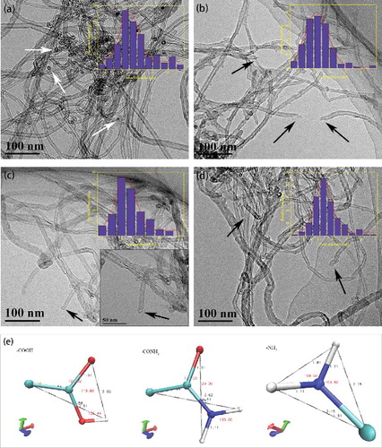
HRTEM can clearly indicate the appearance of carbon nanotubes, so that the inner diameter of the measurement is more accurate. Because the inside and outside diameters of carbon nanotubes were not uniform, the inner diameter of carbon nanotubes were analysed by Gaussian distribution to avoid the individual deviation. Then, the inner modification of CNTs can be illustrated by the change of the inner diameter. shows the HRTEM images of the pristine SWNTs and functionalised SWNTs. It was clear that the pristine SWNTs (a) were curled and agglomerated in aqueous solution, almost all the tips of the pristine SWNTs were closed (pointed by white arrows), which was a feature of unmodified SWNTs. After functionalisation, the samples were well dispersed in aqueous solution and showed a loose morphology. The tips of many SWNTs were opened (pointed by black arrows) as shown in picture (b) (c) (d). In addition, it could be concluded that the chemical treatment under the present condition did not cause any damage to the tubular shape. Moreover, the inner diameter distribution in illustrated that the inner diameter of the pipe became narrower than the original one on the condition that the length of -COOH, -CONH2 and -NH2 were approximately 0.356, 0.365 and 0.215 nm (the length data was obtained by molecular simulation, as shown in Picture (e)), And the inner diameter difference between original CNTs and grafted CNTs was nearly equal to the length of corresponding functional group, which meant that the functional groups were successfully grafted interior to the CNTs.
Figure 1. HRTEM images of: (a) P-SWNT, (b) SWNT-COOH, (c) SWNT-CONH2, (d) SWNT-NH2, (e) the bond length of simulation.
3.1.2. XPS
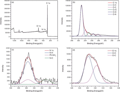
X-ray photoelectron spectroscopy (XPS) was used to confirm the surface functionalisation of the carbon nanotubes. – represented the XPS of P-SWNT, SWNT-COOH, SWNT-COCl, SWNT-CONH2, SWNT-NH2, respectively. showed that the atomic concentrations of carbon (C 1s, 284 ev) and oxygen (O 1s, 531 ev) of P-SWNT were 97.09% and 2.41%. Moreover, the sum of the carbon and oxygen was 1 if impurities were ignored. The binding energy of C element in P-SWNTs could be deconvoluted into four peaks at 283.04, 284.19, 285.35, 286.83 eV, respectively, which corresponded to C-C, C = C, C-H, C-O, respectively. The O 1s spectra displayed two peaks at 529.79 and 531.74 eV, which were attributed to O-H, O-C. showed that carboxylic was successfully attached to SWNTs due to the significant increase of oxygen content (C 85.36%, O 13.47%). In addition, the peakfit of C and O element in (b,c) reconfirmed the successful attachment of COOH group on SWNTs. A new elements chloride (Cl 2p, 198 eV) was also found in , proving that acyl chlorine was successfully grafted on SWNTs with 0.79% content. However, the content of Cl 2p and O 1s was reduced to 0.21% and 7.49% respectively in . This implied that the amides were generated while acyl chlorine was not entirely transformed into amide. Comparing with the peakfit spectra of C and O in and , the keys of C = O disappeared and turned into -NH2, indicating that the carbonyl was replaced by amino.
Figure 2. (a) XPS spectrum of P-SWNT, (b) C 1s, (c) O 1s.
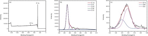
Figure 3. (a) XPS spectrum of SWNT-COOH, (b) C 1s, (c) O 1s.
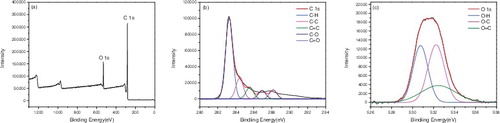
Figure 4. (a) XPS spectrum of SWNT-COCl, (b) C 1s, (c) O 1s.
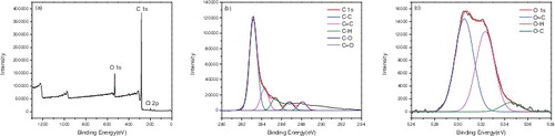
Figure 5. (a) XPS spectrum of SWNT-CONH2, (b) C 1s, (c) N 1s, (d) O 1s.
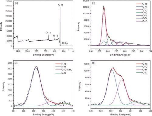
Figure 6. (a) XPS spectrum of SWNT-NH2, (b) C 1s, (c) N 1s, (d) O 1s.
3.1.3. Raman spectra
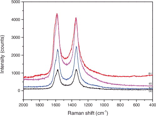
shows the Raman spectra of SWNTs species. (a–d) represents P-SWNT, SWNT-COOH, SWNT-CONH2, SWNT-NH2, respectively. As can be seen from , the peak position of the SWNTs did not change after modification. The D band that appeared in the region around 1340 cm−1 represent amorphous carbon or SP3 carbon atoms. The G band (around 1580 cm−1) represented crystalline carbon or SP2 carbon atoms. Thus, the intensity ratio of D-band to G-band (ID/IG) roughly represented the ratio of amorphous carbon to crystalline carbon, which could be used to characterise the structure of carbon tubes. The ID/IG values of (a) (b) (c) (d) were 1.005, 0.947, 1.070 and 0.956, respectively. The increase of the peak intensity of ID/IG revealed more defects on the surface of carbon tubes or the introduction of functional groups. These decreased ID/IG values of SWNTs suggested that the functional groups grafted on the surfaces of SWNTs probably increase the sole dispersibility of SWNTs. In addition, the strength of the characteristic peaks obviously increased after the chemical treatment. It showed that CNTs were tightly packed with each other after modification, and the number of carbon tubes in unit volume increased [Citation31,Citation32].
Figure 7. Raman spectra of (a) P-SWNT, (b) SWNT-COOH, (c) SWNT-CONH2, (d) SWNT-NH2.
3.1.4. FT-IR
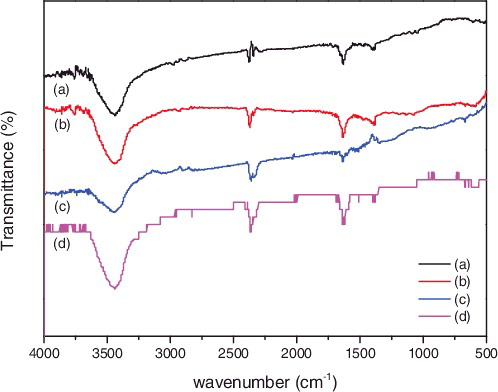
represents the FT-IR spectrum of (a) P-SWNT, (b) SWNT-COOH, (c) SWNT-CONH2, (d) SWNT-NH2, respectively. Compared with (a) and (b), the peaks at 2878 cm−1 and 2975 cm−1 corresponded to the symmetric and asymmetric stretching vibration peak of methylene (-CH2-), which indicated that the structure of methylene was not changed by oxidation. The peaks of C = C aromatic ring stretching appears at the wavenumber of around 1635 cm−1. The new bands appeared at 1721 cm−1, which together with 3440 cm−1 and 1074 cm−1 bands, corresponded to the C = O stretching vibrations and the presence of hydroxyl group (-OH). Those results indicated that the COOH was successfully attached onto SWNTs. The strong stretching vibration absorption peak at the vicinity of 1388 cm−1 in (c) was assigned to bond of C-N, this result clearly indicated that the amide (-CONH2) was successfully attached onto the SWNTs. As well, the amino was grafted on SWNTs as shown in (d) around the wavenumber of 1630 cm−1.
Figure 8. FTIR spectra of functionalized SWNTs: (a) P-SWNT, (b) SWNT-COOH, (c) SWNT-CONH2, (d) SWNT-NH2.
3.1.5. TGA
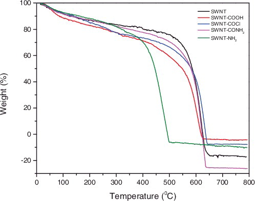
Thermo-gravimetric analyzer (TGA) can not only be used to investigate the thermal stability of modified carbon nanotubes, but also be used to calculate the grafting ratio of the carbon nanotubes. The TGA thermograms of pristine SWNTs and functionalised SWNTs are shown in . (A sample was heat-treated at a linear heating rate of 10 °C/min up to 800 °C under an argon flow). The sample decompositing temperature is subject to change with different functional groups. A slight weight loss around 100 °C could be observed in five curves, which was assigned to weight loss of moisture absorbed in the sample. The obvious weight loss of p-SWNTs was at 500 °C. After modification, the weight loss of SWNT-COOH from 100 to 460 °C assigned to the weight loss of COOH group, and the loss rate was about 22%. For SWNT-COCl, the weight loss rate was about 22% and the chloride was decomposed between 100 and 460 °C. Similarly, SWNT-CONH2 caused a 17% weight loss, which attributed to the decomposition of amide. For SWNT-NH2, a 15% weight loss rate between 100 and 350 °C was due to the decomposition of amino group. In order to probe the reason of negative weight loss in , we did a blank test of crucible thermo-gravimetric experiment. Results showed that the negative in ordinate was ascribed to the thermal weight loss of the crucible.
Figure 9. TGA thermograms of P-SWNT, SWNT-COOH, SWNT-COCl, SWNT-CONH2, SWNT-NH2 (A sample was heat-treated at a linear heating rate of 10 °C/min up to 800 °C under an argon flow).
3.1.6. UV-Vis analysis
In order to explore the effect of different functional groups on the dispersion properties of carbon nanotube in aqueous solution, the sediment percentage of carbon nanotube suspension in a short period of time at the same concentration was measured with UV-Vis spectrophotometer (TU-1901). The less settlement percentage means the higher suspension stability. Aqueous solution of different sample were treated with 30 min ultrasonic, then were scanned by UV-Vis spectrophotometer under 260 nm absorpting wavelength to measure the absorbance of suspension and marked as A0. With the suspension put in high-speed centrifuge (HC-3018) and the speed set to 7000 r/min, the absorbance of supernatant fluid, marked as A1 was measured in high-speed centrifugation. shows the absorbance of different samples under same conditions.
Table 1. The absorbance of different tubes under same conditions. (The maximum absorption wavelength is 260 nm).
The sediment percentage was obtained by the formula: (A0-A1)/A0*100%. shows that the largest sediment percentage was P-SWNT as high as 75.1%, because that P-SWNT was very long and curled. Furthermore, the big particle size together with the poor mutual exclusive effect between carbon nanotubes, made the effective particle size larger and easier to form large aggregates. After centrifugation, the supernatant concentration became significantly lower than the initial concentration, and the settlement percentage was larger. When the functional groups were grafted to the tubes during modification, the degree of entanglement between tubes became lower, which made it difficult to form large aggregate and the stability of suspension was improved accordingly. shows that the dispersing performance of the carbon nanotube was dramatically improved by chemical treatment.
3.1.7. Precipitation method
In order to further measure the stability of the modified carbon nanotubes, this paper studied the water dispersion properties of SWNTs by the precipitation method. P-SWNT, SWNT-COOH, SWNT-COCl, SWNT-CONH2, SWNT-NH2 were dispersed in water and were treated with ultrasonic for 30 min, then were let stand for a period of time. lists the dispersion diagrams after a stand if 0 h (a), 24 h (b), 3 weeks (c), respectively. (Samples from left to right in turn are for P-SWNT, SWNT-COOH, SWNT-COCl, SWNT-CONH2, SWNT-NH2.).
Figure 10. Dispersion and stability of samples after ultrasonic 0 h (a), 24 h (b), 3 week (c).
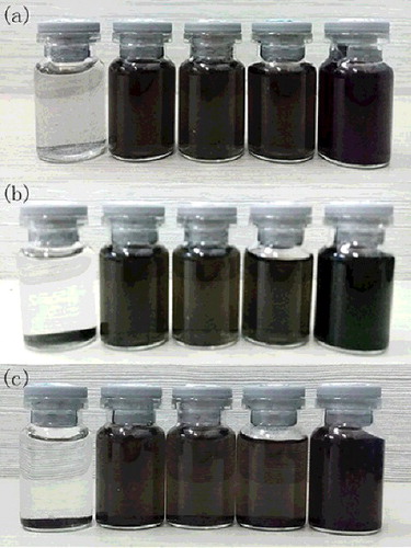
shows that P-SWNT started coagulation precipitation after 24 h, while functionalised SWNTs kept a good dispersity and stability for Three weeks or even longer.
3.2. Characterisation of SWNT-polyamide thin film nanocomposite membrane
3.2.1. SEM
The SEM images of surface morphology of the polyamide and SWNT-polyamide thin film nanocomposite membrane are shown in . Since the surface SEM images of raw SWNTs have similar surface morphologies with functionalised SWNTs, we list only two SEM images of the polyamide film with and without added SWNTs. This phenomenon may be related to the steady spread of single-walled carbon nanotube on surface of the membrane. Compared with the morphology (A and B) of two composite membrane, SWNT-polyamide membrane showed more knot-like structures than PA membrane. This difference of SWNT-polyamide composite surface morphologies was possibly related to the modified SWNTs with hydrophilic functional groups. The reaction rate of amino and TMC was slower than that of MPD and TMC during the interfacial polymerisation process.
Figure 11. The SEM images of surface morphology of (A) PA, (B) PA-SWNTs.
3.2.2. Water flux and salt rejection
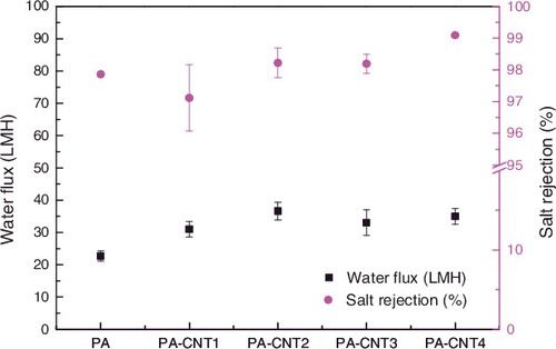
shows the water flux and salt rejection of membranes prepared by various types of CNT (2000 ppm of NaCl feed solution, 2.0 MPa of feed pressure). All membrane performance results shown in are the average values obtained by more than three measurements from the three membrane samples prepared at different times. From this figure, it could be seen that the water flux and salt rejection of SWNT-polyamide membrane increased compared with bare PA membrane. This was because the addition of modified groups within the nanotubes modified hydrophobic carbon nanotubes into hydrophilic one, which made water molecules easier to approach carbon nanotubes. As a result, the water flux increases. The negatively charged group of carbon nanotubes had a positive effect on positively charged Na+ and repels Cl− that prevent Cl− entering carbon nanotubes and attract Na+. The positively charged group was also the same principle. So, the desalination rate increases. What is worth mentioning is that the addition of hydrophilic groups such as carboxyl groups and amino groups, made the water flux and salt rejection of SWNT-polyamide membranes improve dramatically.
Figure 12. Water flux and salt rejection of membranes prepared by various types of CNT (2000 ppm of NaCl feed solution, 2.0 MPa of feed pressure).
3.2.3. Contact angles
Measured values of SWNT-polyamide membrane water contact angle are plotted in . It was found that the contact angle of the SWNT-polyamide membrane was much lower than the PA membrane, indicating that the hydrophilicity of PA-SWNTs composite membrane was improved. The decease of contact angle attributed to, on one hand, incorporating the functionalised SWNTs with hydrophilic groups such as carboxyl groups and amino groups; on the other hand, the reduction of surface roughness.
Figure 13. Contact angle of PA membrane and PA-CNT composite membranes.
4. Conclusion
This article modified the SWNTs with 3.5 nm diameter by using mixed acid (H2SO4, HNO3) oxidation and further modification. The products were characterised by HRTEM, FTIR, XPS, TGA, Raman spectra and UV-Vis, etc. and it was confirmed that carboxyl, carbonyl chloride, amide and amine were successful grafted onto/into the SWNTs. The grafted content of COOH groups was 22%, and the grafting content were 22%, 17% and 15% in SWNT-COCl, SWNT-CONH2 and SWNT-NH2, respectively. By calculating the percentage of settlement and comparing sedimentation experiments, we can draw a conclusion that the dispersion and stability was significantly improved by the functionalised SWNTs than by p-SWNTs. From the evaluation by membrane performance evaluation instrument, it draw a conclusion that the water flux and salt rejection of SWNT-polyamide membrane was increased compared with bare PA membrane. In particular, the addition of hydrophilic groups such as carboxyl groups and amino groups, made the water flux as well as salt rejection of SWNT-polyamide membranes improve dramatically.
Acknowledgement
The authors thank Professor Xueli Gao from Ocean University of China for free use of membrane testing equipment.
Disclosure statement
No potential conflict of interest was reported by the authors.
Additional information
Funding
References
- Iijima S. Helical microtubules of graphitic carbon. Nature. 1991;354:56–58.
- Dervishi E, Li Z, Xu Y, et al. Carbon nanotubes: synthesis, properties, and applications. Parti Sci Technol. 2009;27:107–125.
- Heller I, Kong J, Heering HA, et al. Individual single-walled carbon nanotubes as nanoelectrodes for electrochemistry. Nano Lett. 2005;5:137–142.
- Stoner BR, Brown B, Glass JT. Selected topics on the synthesis, properties and applications of multiwalled carbon nanotubes. Diam Relat Mater. 2014;42:49–57.
- Ajayan PM. Nanotubes from carbon. Chem Rev. 1999;99:1787–1800.
- Williams KA, Veenhuizen TMP, de la Torre BG, et al. Nanotechnology: carbon nanotubes with DNA recognition. Nature. 2002;420:761.
- Battigelli A, Menard-Moyon C, Da Ros T, et al. Endowing carbon nanotubes with biological and biomedical properties by chemical modifications. Adv Drug Deliv Rev. 2013;65:1899–1920.
- Tarfaoui M, Lafdi K, El Moumen A. Mechanical properties of carbon nanotubes based polymer composites. Compos B. 2016;103:113–121.
- Di Giacomo R, Maresca B, Angelillo M, et al. Bio-nano-composite materials constructed with single cells and carbon nanotubes: mechanical, electrical, and optical properties. IEEE Trans Nanotechnol. 2013;12:1026–1030.
- Kotsilkova R, Ivanov E, Krusteva E, et al. Isotactic polypropylene composites reinforced with multiwall carbon nanotubes, part 2: Thermal and mechanical properties related to the structure. J Appl Polym Sci. 2010;115:3576–3585.
- Kyotani T, Nakazaki S, Xu W-H, et al. Chemical modification of the inner walls of carbon nanotubes by HNO3 oxidation. Carbon. 2001;39:782–785.
- Gromov A, Dittmer S, Svensson J, et al. Covalent amino-functionalisation of single-wall carbon nanotubes. J Mater Chem. 2005;15:3334.
- Jing-zhi Z, Jian H, Fei-peng D. Modification of carbon nanotubes with sodium p-aminobenzenesulfonate and its effect on Cu2+ adsorption. New Carbon Mater. 2013;28:14–19.
- Kanbur Y, Küçükyavuz Z. Surface Modification and Characterization of Multi-Walled Carbon Nanotube. Fullerene Nanotubes Carbon Nanostruct. 2011;19:497–504.
- Zhang L, Shi G-Z, Qiu S, et al. Preparation of high-flux thin film nanocomposite reverse osmosis membranes by incorporating functionalized multi-walled carbon nanotubes. Desalin Water Treat. 2011;34:19–24.
- He ZH, Gao GB, Zhang YM. Modification and dispersion of multi-walled carbon nanotubes in water. Russ J Phys Chem. 2014;88:1191–1195.
- Kathi J, Rhee KY. Surface modification of multi-walled carbon nanotubes using 3-aminopropyltriethoxysilane. J Mater Sci. 2008;43:33–37.
- Sawicki R, Mercier L. Evaluation of mesoporous cyclodextrin-silica nanocomposites for the removal of pesticides from aqueous media. Environ Sci Technol. 2006;40:1978–1983.
- Hattori Y, Watanabe Y, Kawasaki S, et al. Carbon-alloying of the rear surfaces of nanotubes by direct fluorination. Carbon. 1999;37:1033–1038.
- Jung C-H, Kim D-K, Choi J-H. Surface modification of multi-walled carbon nanotubes by radiation-induced graft polymerization. Curr Appl Phys. 2009;9:S85–S87.
- Saito T, Matsushige K, Tanaka K. Chemical treatment and modification of multi-walled carbon nanotubes. Physica B. 2002;323:280–283.
- Darabi HR, Jafar Tehrani M, Aghapoor K, et al. A new protocol for the carboxylic acid sidewall functionalization of single-walled carbon nanotubes. Appl Surf Sci. 2012;258:8953–8958.
- Tiwari JN, Tiwari RN, Chang YM, et al. A promising approach to the synthesis of 3D nanoporous graphitic carbon as a unique electrocatalyst support for methanol oxidation. ChemSusChem. 2010;3:460–466.
- Tiwari JN, Kemp KC, Nath K, et al. Interconnected Pt-nanodendrite/DNA/reduced-graphene-oxide hybrid showing remarkable oxygen reduction activity and stability. ACS Nano. 2013;7:9223–9231.
- Verweij H, Schillo MC, Li J. Fast mass transport through carbon nanotube membranes. Small. 2007;3:1996–2004.
- Zhao H, Qiu S, Wu L, et al. Improving the performance of polyamide reverse osmosis membrane by incorporation of modified multi-walled carbon nanotubes. J Membr Sci. 2014;450:249–256.
- Li Q, Yang DF, Shi JS, et al. Biomimetic modification of large diameter carbon nanotubes and the desalination behavior of its reverse osmosis membrane. Desalination. 2016;379:164–171.
- Li Q, Yang DF, Wang JH, et al. Biomimetic modification and desalination behavior of (15,15) carbon nanotubes with a diameter larger than 2 nm. Acta Phys -Chim Sin. 2016;32(X):001–009.
- Lee KP, Arnot TC, Mattia D. A review of reverse osmosis membrane materials for desalination—development to date and future potential. J Membr Sci. 2011;370:1–22.
- Huang H, Qu X, Dong H, et al. Role of NaA zeolites in the interfacial polymerization process towards a polyamide nanocomposite reverse osmosis membrane. RSC Adv. 2013;3:8203.
- Yang J-Y, Shi T-J, Jin W-Y, et al. Modification of multi-walled carbon nanotubes with p-Aminobenzenesulfonic acid by a two-step method. Acta Chim Sin. 2008;66:552–556.
- Cao Z, Qiu L, Yang Y, et al. The effects of surface modifications of multiwalled carbon nanotubes on their dispersibility in different solvents and poly(ether ether ketone). J Mater Res. 2014;29:2625–2633.