
 ?Mathematical formulae have been encoded as MathML and are displayed in this HTML version using MathJax in order to improve their display. Uncheck the box to turn MathJax off. This feature requires Javascript. Click on a formula to zoom.
ABSTRACT
The availability of reliable field data is critical for the advancement of geotechnical engineering. This is particularly the case for piled foundations; due to the substantial geotechnical uncertainties. The settlement (performance) predictions from established analytical methods may deviate from field measurements by as much as an order of magnitude. This paper provides a statistical assessment of the uncertainty of predictions of pile performance under axial loading using an openly accessible geotechnical database of pile load tests from the United Kingdom. The collected database information was classified by pile type, location, test data quality and availability of geotechnical data. With reference to the data from fine-grained soils, two analytical models were employed to predict foundation settlement. The settlement prediction performance was then studied statistically and the model bias and error compared with reference to the aforementioned categories to identify the impact of different sources of uncertainty and evaluate the use of both models for future geotechnical practice. The two models investigated generally over-predict settlement, which is likely due to conservative selection of key model parameters, such as soil strength.
1. Introduction
For axially loaded piles, failure is typically associated with excessive settlement. The available literature on theoretical simulations is vast and encompasses three families of models: approximate analytical formulations in one or multiple dimensions (Randolph and Wroth Citation1978; Baguelin and Frank Citation1980; Scott Citation1981; Mylonakis and Gazetas Citation1998; Mylonakis Citation2001; Guo Citation2012; Anoyatis Citation2013; Vardanega, Williamson, and Bolton Citation2012a; Vardanega et al. Citation2018; Crispin, Leahy, and Mylonakis Citation2018), elastic Green’s functions/boundary-element type solutions (Butterfield and Banerjee Citation1971; Poulos and Davis Citation1980; Kaynia Citation1982; El-Marsafawi Citation1994), finite-element models (Ottaviani Citation1975; Baguelin and Frank Citation1980) and various empirical or semi-empirical schemes (Seed and Reese Citation1957; Coyle and Reese Citation1966; Kraft, Ray, and Kagawa Citation1981). Despite the variety and the sophistication of available models, engineers “may never be able to estimate axial pile capacity in many soil types more accurately [on the average] than about ±30%” (Randolph Citation2003, 848), due to inevitable aleatory uncertainty, which makes piling engineering a challenge even for geotechnical specialists. While the statement of Randolph (Citation2003) refers to pile capacity, it is a salutatory reminder of the very real challenge in predicting to a high degree of accuracy the performance of piled foundations.
Reduction of uncertainty in pile settlement predictions is a fundamental geotechnical engineering need, and therefore, conducting full-scale field tests to establish performance is often necessary on large and/or complex projects. Although such tests are not uncommon in practice, they are expensive, time-consuming and in some cases difficult to carry out and interpret. This frequently leads to conservative design practice which, while acceptable from a safety perspective, does come at a lower value for money. To identify the causes of design conservatism, both system uncertainty and parameter uncertainty should be considered (Bolton Citation1981), which can be difficult when the availability of geotechnical data is low. This can be addressed by developing open databases of high-quality field data. The significance of such online tools has been recognised by various investigators from different countries who have compiled databases with pile data. These include databases from North America (Paikowsky et al. Citation2004), Western Europe (Galbraith, Farrell, and Byrne Citation2014), North Africa (AbdelSalam, Baligh, and El-Naggar Citation2015) and South-East Asia (Ong et al. Citation2021). Global databases have also been recently compiled for tests in sands by a Chinese-UK-Australian consortium (Yang et al. Citation2015, Citation2016) and the Deep Foundation Institute and UC-Irvine (Find A Pile.com, Lemnitzer and Favaretti Citation2013) for lateral-load tests. Phoon and Tang (Citation2019a) have recently combined two databases to study capacity of static load tests on steel piles founded in various soil types. The joint industry research project Pile-Soil Analysis (PISA) has produced significant results and reports detailing premium quality site data (Burd et al. Citation2020a, Citation2020b; Byrne et al. Citation2017, Citation2020; Zdravković et al. Citation2020a, Citation2020b).
In the United Kingdom, a significant volume of piling is carried out on firm clayey sediments. Many results of full-scale pile tests have been reported for London Clay (e.g. Whitaker and Cooke Citation1966; Patel Citation1992), but the raw data is often not openly accessible and is held by various entities. Designers mostly rely on early empirical and analytical models from classic sources such as Skempton (Citation1959), Tomlinson and Woodward (Citation2015), Salgado (Citation2008), and Fleming et al. (Citation2009) to carry out routine design work. The parameters involved in these models are based mostly on judgment and often only a limited number of tests. As codes of practice become more performance oriented, high quality data are essential for calibrating design procedures. Where data is particularly powerful is in calibrating key model parameters e.g. “α-values” (see, for instance: Skempton Citation1959; Patel Citation1992; Salgado Citation2008).
Combining the data collected from load tests on firm clay sediments in the UK is essential for better calibration of geotechnical design models, reducing uncertainty and assessing the potential for foundation re-use by better estimating “reserve capacity” in existing construction. Such data is vital for validating (or falsifying) theoretical models. To this end:
A large, openly accessible UK pile test database categorised according to pile type, location, test data quality and availability of geotechnical data was assembled.
Two easy-to-implement analytical models for non-linear pile settlement by Vardanega, Williamson, and Bolton (Citation2012a); updated in Vardanega et al. (Citation2018) and Crispin, Leahy, and Mylonakis (Citation2018) were employed to predict the settlement of piles embedded in fine-grained deposits.
The settlement predictions of the two models were then compared with measured results from the database and the computed model bias and errors assessed for the aforementioned categories.
Conclusions as to which parameter uncertainties have the most impact on settlement prediction performance are highlighted.
2. Database assembly
A considerable amount of geotechnical data has been obtained since the emergence of soil mechanics as a discipline during the early twentieth century. Much of this information is dispersed and not compiled in a usable manner, either published in a scattered array of conference proceedings, reports, books, dissertations and journals (or in stored box files in the offices of geotechnical engineering consultants). Compiling an opensource electronic database that is UK specific allows for detailed analysis of foundation performance informed by the considerable high-quality geotechnical characterisation data that has already been funded by significant research investments (e.g. Gasparre et al. Citation2007a, Citation2007b; Hight et al. Citation2007 and Kamal et al. Citation2014). High quality testing can be achieved, reported, and employed in analysis and design, as recently demonstrated by the PISA project publications (e.g. Burd et al. Citation2020a, Citation2020b; Byrne et al. Citation2017, Citation2020; Zdravković et al. Citation2020a, Citation2020b). Earlier efforts include the Imperial College Method for piles (Jardine et al. Citation2005, Citation2006). However, for standard construction works such data is rarely available.
The DINGO project (Vardanega et al. Citation2021a, Citation2021b) collected over 500 pile load tests from the UK into an open-source database. The industry data and the publications searched for data from the literature is available in the final project report by Vardanega et al. (Citation2021b) which also includes full details about the building and presentation of the database.
The collected data is comprehensive including various kinds of pile tests (constant rate of penetration (CRP), maintained load (ML), Osterberg style), pile types (bored, driven, cast in situ, continuous flight auger (CFA), straight shafted, under-reamed) and pile materials (concrete, steel, mixed, composite, etc.), locations across the UK and soil types (clay, chalk, sand, superficials, etc.). Nevertheless, some information such as pile Young’s modulus for bored piles, pile axial strains and near-pile excess pore water pressure with depth, and time lag between completion of construction and field testing could not be obtained.
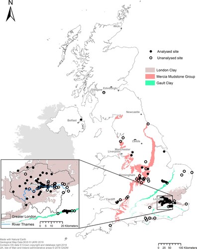
A summary of the variety of types of data is shown in , where the pile tests included in the DINGO Database are subcategorised by: “Geology”, “Data source”, “Pile Type” and “Era of construction” (epoch). No further subcategorisation has been attempted due to the amount of data available. A summary geology map of the DINGO database tests in fine-grained deposits is given in . shows there is good geographical coverage of tests across the UK and a good spread of results in the London area. In this paper, the 186 tests conducted in fine-grained soils were analysed in detail.
Figure 1. Distribution of the DINGO Database pile test in the main subcategories. (Some geology categories are overlapping, i.e. a single pile may be in multiple categories.)
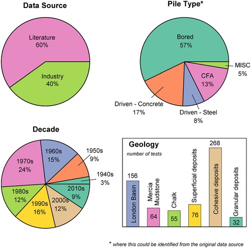
Figure 2. GIS geology map showing the geographic distribution of the DINGO Database tests for fine-grained deposits.
3. Model presentation
Two analytical approaches for pile settlement are reviewed in this section. Both were chosen for their relative ease of use and ability of implementation with hand calculations or a spreadsheet. These closed-form solutions have been employed for simulating axial pile response and performing comparisons with the test data:
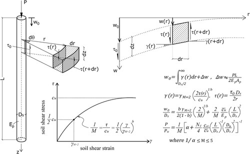
Model 1 is a practical closed-form solution suitable for hand calculation (Vardanega, Williamson, and Bolton Citation2012a; Vardanega et al. Citation2018), based on mobilised strength design (MSD) principles. Model 1 introduces a uniaxial power-law constitutive model for shear stress, a function of shear strain, that allows accounting for material non-linearity in the soil surrounding the pile, and pile compressibility, without sacrificing simplicity in application. The formulation does not, however, account for pile tip resistance and, therefore, gradually loses accuracy as the pile base engages. A summary of the formulation is provided in .
Figure 3. Summary of analytical solution for nonlinear pile settlement considering shearing of concentric cylinders around the pile, pile compression, and non-linear stress-strain relation (strength mobilisation function from Vardanega and Bolton Citation2011a), hereafter referred to as “Model 1” (see Vardanega, Williamson, and Bolton Citation2012a; Vardanega et al. Citation2018 for further details on the development of the model). Symbols are defined in the notation list.
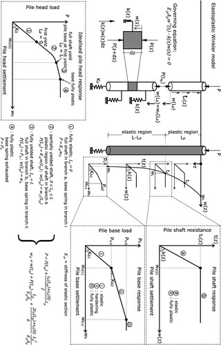
Model 2 is an analytical closed-form elastoplastic solution encompassing depth-dependent soil stiffness and strength in the form of elastic-perfectly plastic “t-z” curves, an elastoplastic tip resistance described by a bilinear force-displacement, and soil yielding propagating unilaterally from the surface towards the base. Based on these assumptions, a closed-form solution for pile settlement is derived (Crispin, Leahy, and Mylonakis Citation2018). The method can easily handle layered profiles such as those encountered in the study at hand and is suitable for spreadsheet or hand calculation. A summary of the formulation is provided in . Additional information on the models is provided in the original publications (Vardanega, Williamson, and Bolton 2012a; Vardanega et al. 2018; Crispin, Leahy, and Mylonakis 2018) and in the follow-up papers of: Vardanega (Citation2015), Voyagaki et al. (Citation2019) and Crispin, Vardanega, and Mylonakis (Citation2019). A wider set of “t-z” curves is given in Bateman et al. (Citation2021).
Figure 4. Summary of analytical solution for elastoplastic pile settlement considering elastic – perfectly plastic shaft resistance and bilinear tip resistance, hereafter referred to as “Model 2” (modified after Crispin, Leahy, and Mylonakis Citation2018, see also Voyagaki et al. Citation2019 for further details regarding Model 2). Symbols are defined in the notation list.
3.1 Factor of safety, F
To present the results in a rational manner an assessment of the factor of safety is needed. To this end, the settlement at the pile head wo was be normalised with the shaft diameter Ds and the applied head force P expressed as a fraction of the nominal bearing capacity Pu for undrained conditions, which, for compression piles, can be estimated using Equation (1):
(1)
(1) where Pu,s and Pu,b are the ultimate shaft and base resistances, respectively.
is the mean undrained shear strength over the pile length, cub is the corresponding value at the tip, Ds is the pile shaft diameter, Db is the pile base diameter, L the pile length, and Nc is the bearing capacity factor for undrained conditions in clay. By casting Equation (1) in the form (P/Pu) the inverse of the design Factor of Safety (Ftotal), Equation (2) can be shown as:
(2)
(2)
4. Parameter selection
A summary of the 186 analysed tests conducted in fine-grained deposits under undrained conditions is shown in . The test sites and corresponding details are reported in the Appendix. The full set of information related to the test data can be accessed via the DINGO Database (Vardanega et al. Citation2021b).
Table 1. Summary statistics of the DINGO pile test database included in this study.
To demonstrate the variability of force-settlement response in the soil deposits studied in this work some fundamental model parameters have been assigned. In some cases, the values for London Clay have been assigned to the whole database due to lack of published information on the other deposits ().
Table 2. Key Model Parameters.
This study does not purport to calibrate the values given in . The main aim of the demonstration is: (a) to compare the field data against a baseline prediction to identify basic trends, (b) validate or falsify different theories as to the causes of the trends, and (c) compare the predictions of Models 1 and 2 to assess the relative importance of input parameters (mainly material properties) on modelling assumptions. The results of a sensitivity study on the importance of the model parameters is provided in the Supplemental data. The authors contend that sensible variations of the parameters listed in will not result in the general trends shown later in the paper changing significantly. Although values in are sensible to represent most of the data available in the database (e.g. suitable for certain deposits such as London Clay), one should accept that site by site and deposit by deposit one may assign different values. However, for instance, the use of α = 0.5 while a London Clay parameter has been used in other UK deposits (e.g. for Gault Clay and Oxford clay, Brettell et al. Citation2021).
It should also be stressed that the nominal failure load in Equation (1) (i.e. instead of the actual measured failure load) is adopted to derive the instantaneous factor of safety when interpreting the data, as a large number of the tests have not been carried out to failure. This would often be a requirement for employing a load test in design, however the focus of this study is on the performance of settlement predictions, therefore any test to a suitable load level has been included. While rigorous capacity prediction methods are available (e.g. Salgado Citation2008; Fleming et al. Citation2009; Guo Citation2012; Viggiani, Mandolini, and Russo Citation2012; Poulos Citation2017), this predicted load is mainly employed to select load levels at which to compare predicted and measured settlements. Therefore, this simple method with no additional input parameters is suitable for the analysis presented in this paper. Finally, even for the tests that have been carried out to failure, matching the measured failure load by means of Equation (1) would require calibration of the strength model parameters, which lies beyond the scope of this paper.
4.1 Soil parameter source
Recognising the critical role of the method of parameter determination on pile response (Poulos Citation1989, Citation1999, Citation2004), the analysed tests have been categorised by the source employed to determine the soil parameters, as shown in (updated from Vardanega et al. Citation2021a). This is split into the source of the soil strength parameters and the soil deformation parameters. Most of the data were Category III (78% of the subset in fine-grained soils) tests that include routine site-specific laboratory strength test data. High-quality deformation data was available from the same deposit (Category B) for the piles in London Clay, which accounted for over half of the data (56% of the subset). However, for a small percentage of the pile tests (4% of the subset) only soil description and/or geology information was available (Category IA). It should be noted that the nature of the dataset available for analysis means that Model 1 and Model 2 cannot be evaluated using site specific soil stiffness parameters as these could not be obtained.
Table 3. Classification of the DINGO data set based on data quality category for the fine-grained soils subset (updated from Vardanega et al. Citation2021a).
As prediction of pile performance requires both soil strength and deformation parameters, certain assumptions are required to allow piles with only Category I, II and/or Category A data to be analysed. Published literature on the soil deposit, such as CIRIA C570 (Chandler and Forster Citation2001) and C47, (Davis and Chandler Citation1973) for piles in Mercia Mudstone, was employed where available to estimate soil strength from a Category I description. Category II SPT data was correlated to undrained shear strength using Stroud (Citation1974). Sites with only Category A deformation data were analysed using the London Clay deformation parameters provided in Vardanega and Bolton (Citation2011b).
Two examples are provided in and for the extreme cases of a Category IIIB and Category IA source respectively. The test pile TP1 shown in , is from site R37-01 in the DINGO Database and was first reported by Patel (Citation1989, Citation1992). The cu(z) line ((b)) is based on triaxial test data from unconsolidated undrained (UU) triaxial compression tests on 100 mm samples from the site. In addition, the founding strata is London Clay, for which published correlations between deformation parameters and strength parameters are available (Vardanega and Bolton Citation2011b). Therefore, this pile is designated as having Category IIIB data.
Figure 5. Site R37-05, pile TP1 (a) Soil profile; (b) undrained shear strength variation with depth; and (c) model parameters derived from the soil investigation data for a database site classified as high quality (IV) and; (d) corresponding predicted load-settlement curves plotted against test data.
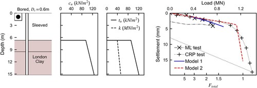
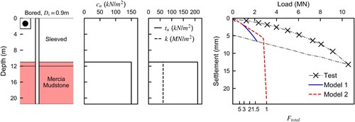
Figure 6. Site R24-01, pile P1(a) Soil profile; (b) undrained shear strength variation with depth; and (c) model parameters derived from the soil investigation data for a database site classified as low quality (I) and; (d) corresponding predicted load-settlement curves plotted against test data.
The maximum shaft resistance per unit length (tu) and Winkler spring stiffness (k) for Model 2 are shown in (c). These are both defined in . (d), shows the corresponding load-settlement curves for each analytical method (Model 1: Vardanega, Williamson, and Bolton (Citation2012a); Vardanega et al. (Citation2018); Model 2: Crispin, Leahy, and Mylonakis (Citation2018)) plotted against the measured experimental data. As evident in (d), both methods give very good predictions of the pile response.
An example where site investigation data do not suffice for direct predictions of the cu profile is given in . The pile test shown is pile P1 from site R24-01 in the DINGO Database and is a test in a site in Mercia Mudstone (MMG), in Cardiff, reported by Kilborn, Treharne, and Zarifian (Citation1989). Available information is limited to soil descriptions, geology and location of the site. The pile was, therefore, designated as Category IA and the cu profile was roughly estimated making the following assumptions based on CIRIA C570 (Chandler and Forster Citation2001): MMG was designated as grade IV and the SPT value from CIRIA C570 (table 3.3 page 29) was used with a Stroud factor of 5 (Stroud Citation1974). The corresponding predicted load – settlement curves are shown in (d), where the agreement with the test results is rather poor.
A full set of the undrained shear strength profiles and model parameters used for the pile tests in this study, as well as measured and predicted load − settlement curves, is provided in the Supplemental data. The instantaneous factor of safety, Ftotal, (equal to the inverse of P/Pu) is also provided.
5. Results
The measured settlements at specific safety factors have been interpolated and compared with predictions from both Model 1 and Model 2. These are shown in for different safety factors, geology categories, pile installation methods, data quality, methods of analysis, pile material properties, and epoch of the tests Note that only the range 0-1% of w0/Ds is shown on Figures 7-14 (see the Supplemental data to obtain the full set of data points). Also note that the number of data points (N) indicated on Figures 7-14 refers to the full set of data analysed in this study. and show results for different values of the instantaneous factor of safety, computed based on Equations (1) and (2), ranging from 1.5 to 5, which are associated with as many as 186 field tests (the number of tests decreases as the applied load increases since in many cases the tests were not carried out to failure). As evident in , points located above the 1:1 line indicate unconservative predictions and vice versa. At low applied loads (Ftotal = 5), both methods seem to provide somewhat conservative predictions. As the load increases, some of the settlement data get significantly overpredicted. However, it is possible that where the capacity is significantly overpredicted by Equation (1), some significantly under-predicted settlements may not visible in the results. This is due to the (expected) absence of measured settlement values above the actual failure load to compare with the relatively low prediction of settlement.
Figure 7. Predicted versus measured pile head settlement plot for the full set of data analysed in this study (model parameters from ).
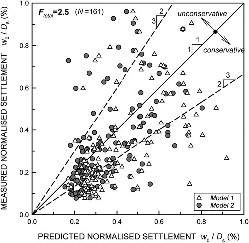
Figure 8. Predicted versus measured pile head settlement plot for different values of factors of safety for the full set of data analysed in this study (model parameters from ).
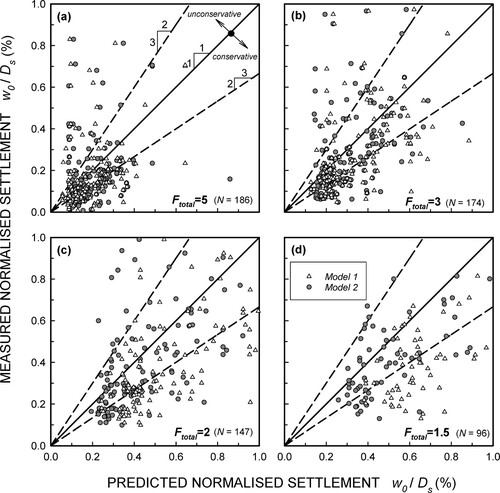
Figure 9. Predicted versus measured pile head settlement plot organised by soil parameter source (categories described in , model parameters from ).
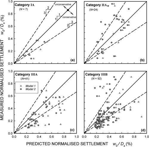
Figure 10. Predicted versus measured pile head settlement plot organised by geology category (parameters from ).
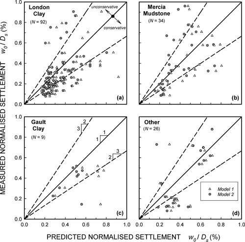
Figure 11. Predicted versus measured pile head settlement plot organised by epoch of the tests (parameters from ).
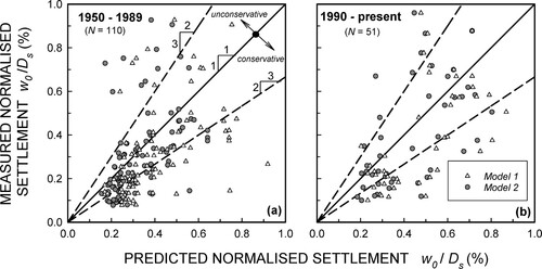
Figure 12. Predicted versus measured pile head settlement plot organised by construction method (parameters from ).
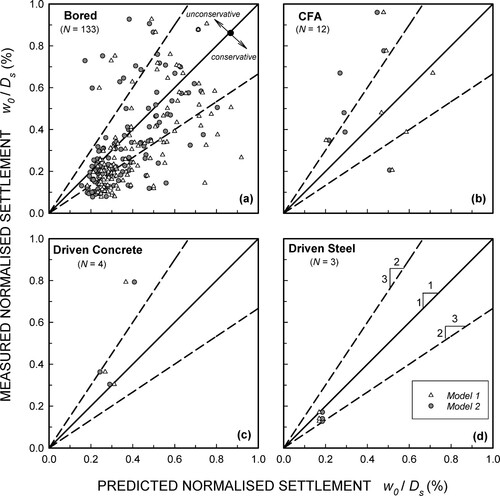
Figure 13. Predicted versus measured pile head settlement plot organised by slenderness of the test pile (parameters from ).
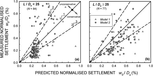
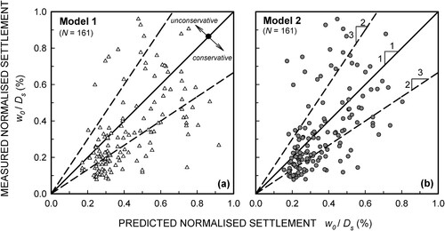
Figure 14. Predicted versus measured pile head settlement comparing Model 1 and Model 2 (parameters from ).
The mean measured normalised settlement is 0.7% and the median is 0.3%. As both the mean and median pile diameter is 0.6 m, this gives settlements of 4 and 2 mm respectively. These low values imply that current pile designs are conservative when considering settlement and, therefore, there is possible reserve capacity available for foundation reuse. However, the standard deviation of the measured normalised settlement is 1.5% which, although it is affected by some significant outliers, highlights the need for settlement prediction in pile design.
For applied loads up to 40% of ultimate (2.5 < Ftotal < 5) and despite the scatter of data, a clustering in measured normalised settlements is observed in and , centred near 0.1% for Ftotal = 5, near 0.15% for Ftotal = 3 and near 0.2% for Ftotal = 2.5. This suggests proportionality between settlement and applied load within the specific dataset. Accordingly, the following simple fitted formula can be considered:
(3)
(3) in which η1 and η2 are fitted coefficients. Based on the above observations, η1 ≈ 0.6, η2 ≈ 0; the above formula goes through the mid-range of the dataset with approximately 50% of the points above and below. This expression can be used as a rule-of-thumb predictor of pile settlement in clay under undrained conditions for P/Pu < 40%.
reports results for four different methods of parameter determination (Categories IA, IIA, IIIA and IIIB) based on 161 field tests split according to . It appears that there is no systematic improvement in the accuracy of the predictions when moving from Category IA to Category IIIB. Specifically, the tendency towards conservative predictions improves when moving from Category IA to Category IIA, yet worsens in Category IIIA and improves again (slightly) in Category IIIB. No improvement in the quality of the predictions is observed between Category IIA (involving in-situ strength data) and IIIB (involving laboratory strength and stiffness data). These observations may suggest that laboratory data may underestimate clay strength (and, indirectly, stiffness) due to sample disturbance, and provides support as to the use of in-situ strength data in pile settlement predictions in clay.
presents data for four different geology categories (London Clay – LC; Gault Clay – GLT, Mercia Mudstone – MMC, and Others). The observed trends are analogous to those in Figures 7–9, with the settlement predictions being somewhat on the conservative side by both methods. An exception is observed with the Mercia Mudstone where there is no apparent bias in the settlement predictions, especially at high loads, and the Gault Clay where the overprediction in settlement is shown to be more considerable (see ).
shows results for the epoch of the tests, grouped in two groups: “old tests” dating from the 1950s to 1980s, and “new tests” dating from the 1990s to 2010s. No clear difference in the quality of the settlement predictions is observed between the two groups, with a tendency for somewhat conservative predictions from both methods being apparent, especially at low loads. This observation suggests that there is not systematic variation with time in the quality of the predictions influenced, say, by better sampling in the field, better testing in the laboratory (e.g. due to the introduction of digital measurements in the 1990s), better equipment in the field etc.
It should be recognised that the method of installing piles, (e.g. drilling with or without support fluids) is another variable in regard to the performance of piles and why often theory has to be replaced with empirical methods from test pile data. In data are split into four groups based on installation method (“Bored”, “Driven-Concrete”, “Driven-Steel”, and “Continuous Flight Auger”). As about 82% of the 161 tests are associated with bored piles, the aforementioned observations refer mostly to the specific group.
Previous studies have subdivided pile response according to the slenderness of the pile, L/Ds (e.g. Patel Citation1992). In the tests are split based on a slenderness of 25 – the calculated median slenderness value for the piles with tests that reached Ftotal = 2.5. The settlement predictions for the slender piles (L/Ds ≥ 25) are, in general, slightly more conservative compared to the predictions for the less slender piles (L/Ds < 25). A cluster of points is visible for the less slender piles; however, this cluster only shows a small variation in predicted values. There is a similar spread of measured values in both plots. This could be due to the smaller range of pile lengths in this slenderness category.
shows data from all tests split in two groups referring to Model 1 and Model 2, for a nominal safety factor of 2.5 (P/Pu = 0.4). No notable differences are observed in the quality of settlement predictions between the two methods, which indicates that the predictions depend mainly on soil properties and to a lesser extent on the method of analysis. Poulos (Citation1999, 13) states that “The selection of geotechnical parameters also plays a major part in the success or otherwise of a prediction, and may outweigh or mask any shortcomings of the method used”. Model 2 provides slightly smaller bias towards conservative settlement predictions, but this comes at a price of increased complexity in the analysis, especially before shaft capacity is exhausted.
The predictions of the two models used in this paper are assessed in terms of (1) bias and (2) error. Bias is calculated considering the model factor B defined as the ratio of the measured settlement to the calculated settlement and given by Equation (4) (e.g. Phoon and Tang Citation2019b; Tang and Phoon Citation2021).
(4)
(4)
Phoon and Kulhawy (Citation1999a, Citation1999b) present a detailed review of statistical metrics and method that can be used to evaluate geotechnical uncertainty and variability and in part emphasise the importance of the coefficient of variation (COV) parameter. The mean and COV (dispersion) for the bias and absolute error are summarised in . A mean and COV of B close to 1 and 0, respectively, correspond to exact predictions, whereas, mean values greater than 1 indicate conservative predictions, while mean values below 1 unconservative. A collection of other models and their bias and dispersion factors have been compared using different databases in the works of Phoon and Tang (Citation2019b) and Tang and Phoon (Citation2021). Most of the calculated bias factors are greater than 1, indicating the predictions are generally conservative. This is particularly evident when more data is available. In addition, the difference between the models is minor; however, Model 2 is marginally more conservative than Model 1, with a slightly lower COV in almost all cases.
Table 4. Statistics of the model bias factors B (Equation 4) and model error presented in .
6. Discussion
After examination of the results shown in , the following main observations can be made: First, there is a tendency towards conservative predictions (i.e. points plotting under the 1:1 line) in most of the graphs. Second, this trend probably cannot be attributed to the analysis method employed, as Models 1 and 2 which are based on rather different assumptions (particularly with reference to tip action), exhibit essentially the same trends (). Likewise, this trend cannot be attributed on soil material type (), epoch of the tests (), construction method (), or pile slenderness (). Third, a clear trend towards improved predictions is observed when field data are used (, Category IIA) over laboratory data, even when high-quality measurements involving both soil strength and stiffness are employed (, Category IIIB). Therefore, the source of the settlement over-prediction should probably be sought in the material properties employed in the analysis, not in the mechanistic models. These properties include: (i) pile stiffness, (ii) soil stiffness (measured directly or inferred from soil strength-to-stiffness correlations), (iii) soil strength.
With reference to pile stiffness (for bored piles which represent about 82% of the dataset), no field or laboratory data are available to allow a proper statistical evaluation of its influence on settlement predictions. Had the dataset included more steel section piles it may have been possible to better ascertain the effect of pile stiffness variability on the prediction quality. The lack of variability of the results depending on epoch of construction may imply that workmanship has not altered significantly during the last 50–70 years, at least in the piling construction industry. However, in light of the results in Figure S1 (Supplemental data), it is unlikely that pile stiffness is responsible for the trends at hand, as these are more or less unaltered for a wide range of Ep values, from 20 GPa to 40 GPa. The minor effect of Ep on pile settlement is backed by theoretical evidence (see Supplemental data).
With reference to soil stiffness (measured directly or inferred via stiffness-to-strength correlations), this naturally controls the behaviour at high factors of safety, yet its influence diminishes at low factors of safety where strength governs pile behaviour. However, had soil stiffness been the main contributor to this effect, this would not justify the trends observed in where the tendency towards more conservative predictions is smaller for high factors of safety (Ftotal = 3 and 5) than for low factors of safety (Ftotal = 2 and 1.5). In other words, settlement predictions improve when soil stiffness governs pile behaviour over soil strength − not the other way around.
The above observations give weight to the postulation that a systematic underpredicted soil strength is present in the dataset. This hypothesis may explain the following key trends: First, the increased quality of the predictions in with an increasing factor of safety i.e. when soil stiffness governs the behaviour, not strength. Second, the surprisingly good performance of Category IIA data (involving in-situ strength data) over Category IIIA and Category IIB (involving laboratory data). This suggests that soil strength measured in the field (even using correlations with SPT data) may provide better predictions than soil strength measured in the laboratory for use in pile analysis. Undrained shear strength is sensitive to test type and shear mode and rate effects (cf. Chen and Kulhawy Citation1993; Mayne et al. Citation2009; Beesley and Vardanega Citation2020; Kulhawy and Mayne Citation1990). Third, it can explain the insensitivity of the observations in soil material type, epoch of tests, construction method, pile slenderness, and method of analysis. Fourth, it can explain the tendency for settlement over-prediction even at high factors of safety, as soil stiffness is often inferred from soil strength (e.g. in Category III data).
The sources for the underprediction in soil strength should be naturally sought in: (1) the disturbance of soil samples collected in the field; (2) the scarcity of high quality in-situ strength measurements (e.g. CPT tests, vane tests) over laboratory measurements. Evidently, conservatism may provide higher safety margins, but does not ensure good predictions of performance.
As a final remark, high-end numerical models such as non-linear FEM, although very powerful in modelling foundation elements such as the one at hand, are not anticipated to alleviate the issue as their performance, like that of the Models 1 and 2, fundamentally depends on the quality of soil material properties they are supplied with. To improve pile settlement predictions, a renewed attention should be made to achieving high quality soil strength and stiffness measurements accompanied by field testing to failure, available in open-source databases.
7. Summary and conclusions
The opensource DINGO Database of over 500 pile load tests in various geological deposits, across the UK has been assembled. The data originated from industrial and literature sources; they are accompanied by site investigation data, have been categorised by geological deposit, pile construction type and epoch; they are user friendly and open to the engineering and scientific community. A subset of 186 pile tests in 57 test sites, in fine-grained soils, in different regions of the country were selected for performing preliminary analyses against two elastoplastic “t-z” analytical closed-form solutions. These are: (i) a power-law non-linear soil model suitable for hand calculations based on mobilisable strength design (MSD) principles and (ii) an analytical closed-form elastoplastic Winkler solution, suitable for spreadsheet or pocket calculator analysis, encompassing depth-dependent elastic-perfectly-plastic “t-z” curves and elastoplastic tip resistance.
The model parameters were calculated based on ground investigation data from the test sites. Where these were not available, values were based on data from similar sites and engineering judgement. The analytical predictions, although based on idealised models, are in good agreement with the test data. Graphs illustrating the predicted vs. measured normalised pile head settlement show a trend towards somewhat conservative predictions of pile settlement. The following conclusions can be drawn:
Comparisons between pile settlement predictions and field measurements from 186 field tests were carried out for five values of the instantaneous factor of safety, ranging from 1.5 to 5. At low loads (Ftotal = 5; P/Pu = 0.2), both methods appear to provide somewhat conservative predictions. However, as the load increases, some of the settlement data get significantly underpredicted.
The mean measured normalised settlement is 0.7% and the median is 0.3%. As both the mean and median pile diameter is 0.6 m, this gives settlements of about 4 and 2 mm, respectively. For safety factors between 2.5 and 5 a clustering in normalised pile head settlement is observed in the data, near 0.1% of the pile shaft diameter for Ftotal = 5, near 0.15% for Ftotal = 3 and near 0.2% for Ftotal = 2.5. This observation suggests proportionality between load and displacement. Based on this observation, Equation (3) can be used as a rule of thumb predictor of pile settlement in clay under undrained conditions for P/Pu < 40%.
No systematic improvement in the accuracy of the predictions is observed when moving from Category IA to Category IIIB data. In fact, the predictions seem to worsen for Category IIIA relative to IIA and improve again for Category IIIB. Moreover, no clear differences in the quality of predictions is observed between Category IIA (involving in-situ strength data) and IIIB (involving laboratory strength and deformation data). This observation provides support towards using in-situ strength data in pile settlement predictions in clay.
Comparisons of settlement predictions and field data in London Clay, Gault Clay, Mercia Mudstone and other soils are analogous to those observed in other classifications, with the settlement predictions being somewhat on the conservative side by both analytical methods. An exception is Mercia Mudstone where there is no apparent bias in settlement predictions, especially at high loads, and the Gault Clay where the overprediction in settlement is rather strong.
No clear difference in the quality of the settlement predictions is observed between “old tests” dating from the 1950s to 1980s, and “new tests” dating from the 1990s to 2010s.
The settlement predictions for “slender” piles (L/Ds ≥ 25) are in general slightly more conservative compared to the predictions for the “less slender” piles (L/Ds < 25). There is a similar spread of measured values in both plots.
Comparisons of predictions from Model 1 and Model 2 for a safety factor of 2.5 (P/Pu = 0.4) show no major differences. This indicates that the predictions depend mainly on the soil properties employed and to a lesser extent on the method of analysis. Model 2 provides slightly smaller bias towards conservative settlement predictions, but this comes at a price of increased complexity, especially before shaft capacity is exhausted.
To move towards genuine performance-based geotechnical design, high-quality databases of field tests complemented by high-quality lab data, are needed to study the consequences of the key design choices made by geotechnical engineers. Traditional design approaches based on conservative selections of design parameters, although acceptable from a safety viewpoint, do not provide high value for money and should be replaced with genuinely performance-based approaches.
| Nomenclature | ||
| Latin symbols | = | definitions |
| Ap | = | pile cross sectional area |
| B | = | model factor |
| b | = | soil non-linearity exponent |
| cu | = | undrained shear strength |
| cub | = | undrained shear strength at pile base |
| = | average undrained shear strength | |
| Ds | = | pile shaft diameter |
| Db | = | pile base diameter |
| Ep | = | elastic modulus of the pile |
| Es | = | elastic modulus of soil |
| Ftotal | = | overall factor of safety |
| Gs(z) | = | soil shear modulus at depth z |
| Kel | = | head stiffness of elastic region of pile |
| Kb | = | pile base stiffness |
| Kb1, Kb2 | = | pile base stiffness in region i, pile base stiffness in region ii |
| k(z) | = | Winkler spring stiffness at depth z |
| L | = | pile length |
| Lp | = | length of plastic region of pile |
| M | = | soil strength mobilisation factor |
| N | = | number of data points |
| Nc | = | bearing capacity factor |
| P(z) | = | pile axial load at depth z |
| P, Pb, Ps | = | total applied load, applied base load, applied shaft load |
| Pu,y | = | pile base load when shaft resistance exhausted |
| Pu, Pu,b, Pu,s | = | total ultimate resistance (bearing capacity), ultimate base resistance, ultimate shaft resistance |
| r | = | radial distance from pile axis |
| tu(z) | = | ultimate skin friction per unit length at depth z |
| w(z) | = | pile settlement at depth z |
| w0, wb, Δw | = | pile head settlement, pile base settlement, pile elastic shortening |
| wby | = | pile base yield settlement |
| wy(z) | = | soil yield settlement at depth z |
| z | = | depth below ground level |
| Greek symbols | = | definitions |
| α | = | adhesion factor |
| γ | = | shear strain |
| γM=2 | = | shear strain when half the undrained shear strength cu is mobilised |
| η1, η2 | = | fitted coefficients |
| νs | = | soil Poisson’s ratio |
| ρ | = | vertical soil inhomogeneity constant |
| τ, το | = | shear stress, shear stress at the pile-soil interface |
| τ(r) | = | shear stress attenuation function |
NGRK-2020-0102-File021.pdf
Download PDF (3.5 MB)Acknowledgements
Thanks are due to Sergio Solera, of Mott Macdonald, for sharing load test data from bored and CFA piles terminating in sands and gravels; and to Malcolm Woodruff for sharing data from the Isle of Wight. Finally, the authors are grateful to Mark Shaw, of Highways England, for facilitating access to the HAGDMS database. The authors thank Dr Melvin England for his support of the DINGO project and his helpful comments and suggestions.
Disclosure statement
No potential conflict of interest was reported by the authors.
Data availability
The underlying data used for the analysis presented in this paper can be sourced from the DINGO database which can be freely downloaded from the data.bris repository via the following weblink: https://doi.org/10.5523/bris.89r3npvewel2ea8ttb67ku4d (Vardanega et al. Citation2021b).
Correction Statement
This article has been republished with minor changes. These changes do not impact the academic content of the article.
Additional information
Funding
References
- AbdelSalam, S. S., F. A. Baligh, and H. M. El-Naggar. 2015. “A Database to Ensure Reliability of Bored Pile Design in Egypt.” Proceedings of the Institution of Civil Engineers – Geotechnical Engineering 168 (2): 131–143. doi:10.1680/geng.14.00051.
- Anoyatis, G. M. 2013. “Contribution to Kinematic and Inertial Analysis of Piles by Analytical and Experimental Methods.” Ph.D. thesis. University of Patras, Patras, Greece.
- Baguelin, F., and R. Frank. 1980. “Theoretical Studies of Piles Using the Finite Element Method.” In Numerical Methods in Offshore Piling, edited by I. M. Smith, P. George and W. J. Rigden, 83–91. London: Institution of Civil Engineers (ICE).
- Bateman, A. H., J. J. Crispin, P. J. Vardanega, and G. E. Mylonakis. 2021. Theoretical “t-z” Curves for Axially-Loaded Piles. under review.
- Beesley, M. B., and P. J. Vardanega. 2020. “Parameter Variability of Undrained Shear Strength and Strain Using a Database of Reconstituted Soil Tests.” Canadian Geotechnical Journal 57 (8): 1247–1255. doi:10.1139/cgj-2019-0424.
- Bolton, M. D. 1981. “Limit State Design in Geotechnical Engineering.” Ground Engineering 14 (6): 39–46.
- Brettell, T. R., R. P. Dowling, M. A. Wiechecki, P. A. Nowak, and J. D. Maddison. 2021. “Large Diameter Pile Foundations in Heavily Overconsolidated Strata: A14 Cambridge to Huntington Improvement Scheme Case History.” In Piling 2020: Proceedings of the Piling 2020 Conference, edited by K. G. Higgins, Y. Ainsworth, D. G. Toll, and A. S. Osman, 399–404. London: ICE Publishing.
- Burd, H. J., W. J. A. P. Beuckelaers, B. W. Byrne, K. Gavin, G. T. Houlsby, D. Igoe, R. J. Jardine, et al. 2020a. “New Data Analysis Methods for Instrumented Medium Scale Monopile Field Tests.” Géotechnique 70 (11): 961–969. doi:10.1680/jgeot.18.pisa.002.
- Burd, H. J., D. M. G. Taborda, L. Zdravković, C. N. Abadie, B. W. Byrne, G. T. Houlsby, K. Gavin, et al. 2020b. “PISA Design Model for Monopiles for Offshore Wind Turbines: Application to a Marine Sand.” Géotechnique 70 (11): 1048–1066. doi:10.1680/jgeot.18.P.277.
- Butterfield, R., and P. K. Banerjee. 1971. “The Elastic Analysis of Compressible Piles and Pile Groups.” Géotechnique 21 (1): 43–60. doi:10.1680/geot.1971.21.1.43.
- Byrne, B. W., R. A. McAdam, H. J. Burd, W. J. A. P. Beuckelaers, K. Gavin, G. T. Houlsby, D. Igoe, et al. 2020. “Monotonic Lateral Loaded Pile Testing in a Stiff Glacial Clay Till at Cowden.” Géotechnique 70 (11): 970–985. doi:10.1680/jgeot.18.pisa.003.
- Byrne, B. W., R. A. McAdam, H. J. Burd, G. T. Houlsby, C. M. Martin, W. J. A. P. Beuckelaers, L. Zdravkovic, et al. 2017. PISA: New Design Methods for Offshore Wind Turbine Monopiles, In: Offshore Site Investigation Geotechnics: Smarter Solutions for Future Offshore Developments. Proceedings of the 8th International Conference 12-14 September 2017, Royal Geographical Society, London, UK, Society for Underwater Technology, pp. 142-161. https://doi.org/10.3723/OSIG17.142.
- Chandler, R. J., and A. Forster. 2001. Engineering in Mercia Mudstone. Report C570, Construction Industry Research and Information Association (CIRIA), Westminster, London, UK.
- Chen, Y. J., and F. H. Kulhawy. 1993. “Undrained Strength Interrelationships Among CIUC, UU, and UC Tests.” Journal of Geotechnical Engineering (American Society of Civil Engineers) 119 (11): 1732–1750. doi:10.1061/(ASCE)0733-9410(1993)119:11(1732).
- Coyle, H. M., and L. C. Reese. 1966. “Load Transfer for Axially Loaded Piles in Clay.” Journal of the Soil Mechanics and Foundations Division (American Society of Civil Engineers) 92 (2): 1–26.
- Crispin, J. J., C. P. Leahy, and G. Mylonakis. 2018. “Winkler Model for Axially-Loaded Piles in Inhomogeneous Soil.” Géotechnique Letters 8 (4): 290–297. doi:10.1680/jgele.18.00062.
- Crispin J.J., Vardanega P.J. and Mylonakis G. 2019. Prediction of pile settlement using simplified models. In Proceedings of the XVII European Conference on Soil Mechanics and Geotechnical Engineering, Reykjavik, Iceland, September 1-6, 2019, Geotechnical Engineering, foundation of the future (Sigursteinsson, H., Erlingsson, S. and Bessason, B. eds.), paper 388, 8pp. Accessed August 27, 2021. https://www.issmge.org/uploads/publications/51/75/0388-ecsmge-2019_Crispin.pdf.
- Davis, A. G., and R. J. Chandler. 1973. Further Work on the Engineering Properties of Keuper Marl. Report 47, Construction Industry Research and Information Association (CIRIA), Westminster, London, UK.
- El-Marsafawi, H. G. 1994. “Dynamic Analysis of Single Piles and Pile Groups.” Ph.D. thesis., The University of Western Ontario, London, Ontario, Canada.
- Fleming, W. G. K. 1992. “A new Method for Single Pile Settlement Prediction and Analysis.” Géotechnique 42 (3): 411–425. doi:10.1680/geot.1992.42.3.411.
- Fleming, W. G. K., A. J. Weltman, M. F. Randolph, and W. K. Elson. 2009. Piling Engineering. 3rd ed. New York: Wiley.
- Galbraith, A. P., E. R. Farrell, and J. J. Byrne. 2014. “Uncertainty in Pile Resistance from Static Load Tests Database.” Proceedings of the Institution of Civil Engineers - Geotechnical Engineering 167 (5): 431–446. doi:10.1680/geng.12.00132.
- Gasparre, A., S. Nishimura, M. R. Coop, and R. J. Jardine. 2007a. “The Influence of Structure on the Behaviour of London Clay.” Géotechnique 57 (1): 19–31. doi:10.1680/geot.2007.57.1.19.
- Gasparre, A., S. Nishimura, N. A. Minh, M. R. Coop, and R. J. Jardine. 2007b. “The Stiffness of Natural London Clay.” Géotechnique 57 (1): 33–47. doi:10.1680/geot.2007.57.1.33.
- Guo, W. D. 2012. Theory and Practice of Pile Foundations. Boca Raton: CRC Press Taylor & Francis Group.
- Hight, D. W., A. Gasparre, S. Nishimura, N. A. Minh, R. J. Jardine, and M. R. Coop. 2007. “Characteristics of the London Clay from the Terminal 5 Site at Heathrow Airport.” Géotechnique 57 (1): 3–18. doi:10.1680/geot.2007.57.1.3.
- Jardine, R. J., F. C. Chow, R. Overy, and J. R. Standing. 2005. ICP Design Methods for Driven Piles in Sands and Clays. London: Thomas Telford Ltd.
- Jardine, R. J., J. R. Standing, and F. C. Chow. 2006. “Some Observations of the Effects of Time on the Capacity of Piles Driven in Sand.” Géotechnique 56 (4): 227–244. doi:10.1680/geot.2006.56.4.227.
- Kamal, R. H., M. R. Coop, R. J. Jardine, and A. Brosse. 2014. “The Post-Yield Behaviour of Four Eocene-to-Jurassic UK Stiff Clays.” Géotechnique 64 (8): 620–634. doi:10.1680/geot.13.P.043.
- Kaynia, A. M. 1982. “Dynamic Stiffness and Seismic Response of Pile Groups.” Ph.D. thesis, Massachusetts Institute of Technology, Boston, MA, USA.
- Kilborn, N. S., G. Treharne, and V. Zarifian. 1989. The Use of the Standard Penetration Test for the Design of Bored Piles in the Keuper Marl of Cardiff. In: Penetration Testing in the UK: Proceedings of the Geotechnology Conference Organized by the Institution of Civil Engineers and held in Birmingham on 6–8 July 1988. Thomas Telford, London, UK.
- Kraft, L. M., R. P. Ray, and T. Kagawa. 1981. “Theoretical t-z Curves.” Journal of the Geotechnical Engineering Division (American Society of Civil Engineers) 107 (11): 1543–1561.
- Kulhawy, F. H., and P. W. Mayne. 1990. Manual on Estimating Soil Properties for Foundation Design. EL-6800 Research Project 1493-6, Final Report, August 1990.
- Lemnitzer, A., and C. Favaretti. 2013. Find a Pile.com. Accessed June 10, 2020, http://www.findapile.com/.
- London District Surveyors Association (LDSA). 2017. Foundations no. 1: Guidance Notes for the Design of Straight Shafted Bored Piles in London Clay. London: London District Surveyor's Association Publications.
- Mayne, P. W., M. R. Coop, S. Springman, A. An-Bin Huang, and J. Zornberg. 2009. Geomaterial Behavior and Testing. In: Proceedings of the 17th International Conference in Soil Mechanics & Geotechnical Engineering (ICSMGE), Alexandria, vol. 4, pp. 2777-2872. Accessed June 10, 2021, https://www.issmge.org/uploads/publications/1/21/STAL9781607500315-2777.pdf.
- Meyerhof, G. G. 1976. “Bearing Capacity and Settlement of Pile Foundations (11th Terzaghi Lecture).” Journal of the Geotechnical Engineering Division (American Society of Civil Engineers) 102 (3): 195–228.
- Mylonakis, G. 2001. “Winkler Modulus for Axially Loaded Piles.” Géotechnique 51 (5): 455–461. doi:10.1680/geot.2001.51.5.455.
- Mylonakis, G., and G. Gazetas. 1998. “Settlement and Additional Internal Forces of Grouped Piles in Layered Soil.” Géotechnique 48 (1): 55–72. doi:10.1680/geot.1998.48.1.55.
- Ong, Y. H., C. T. Toh, S. K. Chee, and H. Mohamad. 2021. “Bored Piles in Tropical Soils and Rocks: Shaft and Base Resistances, t–z and q–w Models.” Proceedings of the Institution of Civil Engineers – Geotechnical Engineering 174 (2): 193–224. doi:10.1680/jgeen.19.00106.
- Ottaviani, M. 1975. “Three-dimensional Finite Element Analysis of Vertically Loaded Pile Groups.” Géotechnique 25 (2): 159–174. doi:10.1680/geot.1975.25.2.159.
- Paikowsky, S. G., B. Brigisson, M. McVay, T. Nguyen, C. Kuo, G. Baecher, B. Ayyub, et al. 2004. Load and Resistance Factor Design (LRFD) for Deep Foundations. NCHRP Report 507, National Cooperative Highway Research Program, Transportation Research Board, Washington, DC, USA.
- Patel, D. C. 1989. “A Case Study of the Shaft Friction of Bored Piles in London Clay in Terms of Total and Effective Stresses.” M.Sc. thesis, Imperial College London, UK.
- Patel, D. C. 1992. “Interpretation of Results of Pile Tests in London Clay.” In Piling: European Practice and Worldwide Trends, 100–110. London: Thomas Telford.
- Phoon, K.-K., and F. W. Kulhawy. 1999a. “Characterisation of Geotechnical Variability.” Canadian Geotechnical Journal 36 (4): 612–624. doi:10.1139/t99-038.
- Phoon, K.-K., and F. W. Kulhawy. 1999b. “Evaluation of Geotechnical Property Variability.” Canadian Geotechnical Journal 36 (4): 625–639. doi:10.1139/t99-039.
- Phoon, K.-K., and C. Tang. 2019a. “Effect of Extrapolation on Interpreted Capacity and Model Statistics of Steel H-Piles.” Georisk: Assessment and Management of Risk for Engineered Systems and Geohazards 13 (4): 291–302. doi:10.1080/17499518.2019.1652920.
- Phoon, K.-K., and C. Tang. 2019b. “Characterisation of Geotechnical Model Uncertainty.” Georisk: Assessment and Management of Risk for Engineered Systems and Geohazards 13 (2): 101–130. doi:10.1080/17499518.2019.1585545.
- Poulos, H. G. 1989. “Pile Behaviour – Theory and Application.” Géotechnique 39 (3): 365–415. doi:10.1680/geot.1989.39.3.365.
- Poulos, H. G. 1999. “Common Procedures for Foundation Settlement Analysis – Are They Adequate?” Australian Geomechanics Journal 34 (1): 13–38.
- Poulos, H. G. 2004. An Approach for Assessing Geotechnical Reduction Factors for Pile Design. In: Proceedings of the 9th Australia New Zealand Conference on Geomechanics Auckland, New Zealand, vol. 1, pp. 109–115. Accessed June 06, 2021. https://www.issmge.org/uploads/publications/89/103/9ANZ_009.pdf.
- Poulos, H. G. 2017. Tall Building Foundation Design. Boca Raton: CRC Press.
- Poulos, H. G., and E. H. Davis. 1980. Pile Foundation Analysis and Design. New York: Wiley.
- Randolph, M. F. 2003. “Science and Empiricism in Pile Foundation Design.” Géotechnique 53 (10): 847–875. doi:10.1680/geot.2003.53.10.847.
- Randolph, M. F., and C. P. Wroth. 1978. “Analysis of Deformation of Vertically Loaded Piles.” Journal of the Geotechnical Engineering Division (American Society of Civil Engineers) 104 (12): 1465–1488.
- Salgado, R. 2008. The Engineering of Foundations. Boston: McGraw Hill.
- Scott, R. F. 1981. Foundation Analysis. Englewood Cliffs: Prentice Hall.
- Seed, H. B., and L. C. Reese. 1957. “The Action of Soft Clay Along Friction Piles.” Transactions of the American Society of Civil Engineers 122: 731–764.
- Skempton, A. W. 1959. “Cast-in-situ Bored Piles in London Clay.” Géotechnique 9 (4): 153–173. doi:10.1680/geot.1959.9.4.153.
- Stroud, M. A. 1974. The Standard Penetration Test in Insensitive Clays and Soft Rocks. In: Proceedings of the European symposium on penetration testing, vol. 2 (part 2), pp. 367-375. National Swedish Building Research, Stockholm, Sweden.
- Tang, C., and K.-K. Phoon. 2021. Model Uncertainties in Foundation Design. Abingdon Oxford: CRC Press.
- Tomlinson, M., and J. Woodward. 2015. Pile Design and Construction in Practice. 6th ed. Boca Raton: CRC Press Taylor & Francis Group.
- Vardanega, P. J. 2015. “Sensitivity of Simplified Pile Settlement Calculations to Parameter Variation in Stiff Clay.” In Geotechnical Engineering for Infrastructure and Development. vol. 7, edited by M. G. Winter, D. M. Smith, P. J. L. Eldred, and D. G. Toll, 3777–3782. London: ICE Publishing.
- Vardanega, P. J., and M. D. Bolton. 2011a. “Strength Mobilization in Clays and Silts.” Canadian Geotechnical Journal 48 (10): 1485–1503. and corrigendum, 49(5), 631, http://doi.org/10.1139/t2012-023.
- Vardanega, P. J., and M. D. Bolton. 2011b. “Predicting Shear Strength Mobilisation of London Clay.” In Proceedings 15th European Conference on Soil Mechanics and Geotechnical Engineering: Geotechnics of Hard Soils – Weak Rocks. vol. 1, edited by A. Anagnostopoulos, M. Pachakis, and C. Tsatsanifos, 487–492. Amsterdam: IOS Press. http://doi.org/10.3233/978-1-60750-801-4-487.
- Vardanega, P. J., J. J. Crispin, C. E. L. Gilder, E. Voyagaki, and K. Ntassiou. 2021a. “DINGO: A Pile Load Test Database.” In Piling: Proceedings of the Piling 2020 Conference, edited by K. G. Higgins, Y. Ainsworth, D. G. Toll, and A. S. Osman, 229–234. London: ICE Publishing.
- Vardanega, P. J., J. J. Crispin, C. E. L. Gilder, E. Voyagaki, C. J. Shepheard, and E. A. Holcombe. 2018. “Geodatabases to Improve Geotechnical Design and Modelling.” ce/papers 2 (2-3): 401–406. doi:10.1002/cepa.704.
- Vardanega, P. J., E. Kolody, S. H. Pennington, P. R. J. Morrison, and B. Simpson. 2012b. “Bored Pile Design in Stiff Clay I: Codes of Practice.” Proceedings of the Institution of Civil Engineers - Geotechnical Engineering 165 (4): 213–232. doi:10.1680/geng.11.00062.
- Vardanega, P. J., E. Voyagaki, J. J. Crispin, C. E. L. Gilder, and K. Ntassiou. 2021b. The DINGO Database: Summary Report: April 2021, v1.1. Bristol: University of Bristol. https://doi.org/10.5523/bris.89r3npvewel2ea8ttb67ku4d.
- Vardanega, P. J., M. G. Williamson, and M. D. Bolton. 2012a. “Bored Pile Design in Stiff Clay II: Mechanisms and Uncertainty.” Proceedings of the Institution of Civil Engineers - Geotechnical Engineering 165 (4): 233–246. and corrigendum, 166(5), 518. https://doi.org/10.1680/geng.2013.166.5.518.
- Viggiani, C., A. Mandolini, and G. Russo. 2012. Piles and Pile Foundations. 1st Ed. London and New York: Spon Press, Taylor & Francis.
- Voyagaki, E., J. Crispin, C. Gilder, P. Nowak, N. O'Riordan, D. Patel, and P. J. Vardanega. 2019. “Analytical Approaches to Predict Pile Settlement in London Clay.” In Sustainability Issues for the Deep Foundations. GeoMEast 2018. Sustainable Civil Infrastructures, edited by H. El-Naggar, K. Abdel-Rahman, B. Fellenius, and H. Shehata, 162–180. Cham: Springer. https://doi.org/10.1007/978-3-030-01902-0_14.
- Whitaker, T., and R. W. Cooke. 1966. An Investigation of the Shaft and Base Resistance of Large Bored Piles in London Clay. In: Large Bored Piles: Proceedings of the Symposium by the Institution of Civil Engineers and the Reinforced Concrete Association; Institution of Civil Engineers, London, UK, pp. 7-49.
- Yang, Z., R. Jardine, W. Guo, and F. Chow. 2015. “A New and Openly Accessible Database of Tests on Piles Driven in Sands.” Géotechnique Letters 5 (1): 12–20. doi:10.1680/geolett.14.00075.
- Yang, Z., R. Jardine, W. Guo, and F. Chow. 2016. A Comprehensive Database of Tests on Axially Loaded Piles Driven in Sand. Amsterdam: Elsevier.
- Zdravković, L., R. J. Jardine, D. M. G. Taborda, D. Abadias, H. J. Burd, B. W. Byrne, K. Gavin, et al. 2020a. “Ground Characterisation for PISA Pile Testing and Analysis.” Géotechnique 70 (11): 945–960. doi:10.1680/jgeot.18.pisa.001.
- Zdravković, L., D. M. G. Taborda, D. M. Potts, D. Abadias, H. J. Burd, B. W. Byrne, K. Gavin, et al. 2020b. “Finite Element Modelling of Laterally Loaded Piles in a Stiff Glacial Clay Till at Cowden.” Géotechnique 70 (11): 999–1013. https://doi.org/10.1680/jgeot.18.pisa.005.
Appendix
Table A1. Summary of 57 pile test sites from the DINGO Database analysed in this study (Geology codes are listed in DINGO Database (Vardanega et al. Citation2021b)).