
 ?Mathematical formulae have been encoded as MathML and are displayed in this HTML version using MathJax in order to improve their display. Uncheck the box to turn MathJax off. This feature requires Javascript. Click on a formula to zoom.
ABSTRACT
The recent fast development in computer vision and mobile sensor technology such as mobile LiDAR and RGB-D cameras is pushing the boundary of the technology to suit the need of real-life applications in the fields of Augmented Reality (AR), robotics, indoor GIS and self-driving. Camera localization is often a key and enabling technology among these applications. In this paper, we developed a novel camera localization workflow based on a highly accurate 3D prior map optimized by our RGB-D SLAM method in conjunction with a deep learning routine trained using consecutive video frames labeled with high precision camera pose. Furthermore, an AR registration method tightly coupled with a game engine is proposed, which incorporates the proposed localization algorithm and aligns the real Kinetic camera with a virtual camera of the game engine to facilitate AR application development in an integrated manner. The experimental results show that the localization accuracy can achieve an average error of 35 cm based on a fine-tuned prior 3D feature database at 3 cm accuracy compared against the ground-truth 3D LiDAR map. The influence of the localization accuracy on the visual effect of AR overlay is also demonstrated and the alignment of the real and virtual camera streamlines the implementation of AR fire emergency response demo in a Virtual Geographic Environment.
1. Introduction
Camera localization is currently a very active research field due to the rapid development and technological advances in mobile computing, computer vision, Augmented Reality (AR), indoor GIS and SLAM (Simultaneous Localization and Mapping) technology. The increasing use of mobile phones and UAVs (Unmanned Aerial Vehicles) is pushing the boundary of the technology to suit the need of real-life applications in the fields of AR, robotics, indoor GIS and self-driving (Gavrila et al. Citation2001; Akçayır and Akçayır Citation2017; Jo and Kim Citation2016; Rameau et al. Citation2016). In these emerging applications, camera localization is often a key and enabling technology. Recent sensors such as portable LiDAR (Light Detection and Ranging) and RGB-D cameras complement RGB imagery with depth information, which provides new opportunities for developing robust and practical applications while RGB cameras alone may be insufficient.
Camera localization is a key step in both on-line SLAM (Dine et al. Citation2016) and off-line SFM (Structure From Motion) (Schönberger and Frahm Citation2016). For example, the recent noteworthy development in real-time SLAM algorithms is called ORB-SLAM (Raúl, Montiel, and Tardós Citation2015) which incorporates the state-of-the-art techniques in recent years, and uses real-time ORB features for tracking, mapping, localization and loop closure in large indoor and outdoor environments. In addition to the on-line SLAM, Schönberger and Frahm (Citation2016) developed a number of techniques including scene graph augmentation, next best view selection, efficient and robust bundle adjustment and triangulation, to make a further step towards a truly general-purpose off-line SFM pipeline. It can be seen that both SLAM and SFM techniques have become more practical than ever and made a further step towards their widespread use in real-life scenarios in terms of accuracy, scalability, robustness, efficiency and completeness. In the meantime, the cost of compact LiDAR and RGB-D sensors is coming down significantly, which permits the development of more accurate and robust localization algorithms using sensor fusion techniques. One such example is presented in Taketomi, Sato, and Yokoya (Citation2011) and Taketomi, Sato, and Yokoya (Citation2008), in which point cloud output by LIDAR sensor is fused with off-line SFM data to improve stability and accuracy of real-time camera pose estimation and thus provide users with smooth and comfortable AR experiences with less jittering. In mission-critical applications such as self-driving, mobile LiDAR sensors are often integrated with RGB cameras to enhance self-driving car’s capability of environmental perception (Li et al. Citation2017). Moreover, building upon the recent SLAM and SFM technology, the dense 3D reconstruction with RGB-D and compact LiDAR sensors on portable mapping platform now serves as a reliable and abundant data source for constructing detailed indoor maps and indoor GIS. Such advances in 3D mapping technologies with feature extraction provide a great technological means to facilitate the seamless integration of indoor and outdoor GIS in a semantic-rich and scalable way.
AR applications rely on camera localization techniques which can be classified into model based and on-line methods (Reitmayr and Drummond Citation2006; Behringer, Park, and Sundareswaran Citation2002; Bleser and Stricker Citation2009). The on-line methods (e.g. SLAM) inevitably suffer from accumulated error as the cameras travel along. As a result, the camera position and orientation error usually build up over time especially in large-scale scenes and may subsequently disrupt the usability of AR applications. At present, AR applications are often restricted to a small workspace such as those running on iPhoneX and other mobiles such as in Wagner et al. (Citation2010), Microsoft Hololens have made a remarkable step in achieving large-scale AR applications. However, camera localization in unknown AR large scenes remains challenging in terms of robustness and accuracy, and may prohibit the widespread use of AR technology (Rehman and Cao Citation2017). Nevertheless, model-based camera localization relies on a prebuilt map of the environment to localize the camera such as in (Li and Fan Citation2015) while the on-line methods build the map and localize the camera simultaneously with accumulated error (e.g. SLAM). It should be noted that the map building process can be separated from camera localization because many real-life applications such as indoor positioning, self-driving and AR may not require real-time map building and an accurate prior map would often simplify the camera localization task and improve the accuracy and robustness. However, there are currently very few studies addressing camera localization accuracy within prebuilt maps captured by recent sensors such as LiDAR and RGB-D sensors in the context of AR and indoor positioning. Moreover, very few research is able to assess the absolute accuracy of the prior map and the localization. Therefore, the objective of this research is to evaluate the effectiveness and accuracy of camera localization using the 3D feature prior map captured by the recent RGB-D and LiDAR sensors in the context of AR and indoor positioning. More specifically, our original contributions are: (1) a novel camera localization workflow based on an accurate 3D prior map optimized by our RGB-D SLAM method in conjunction with a deep learning routine trained using consecutive video frames labeled with high precision camera pose. The map is built by our state-of-the-art RGB-D SLAM algorithms on extended bundle adjustment with both visual and depth data; (2) to evaluate the 3D map quality by registration with high density point cloud acquired from both terrestrial and mobile laser scanners and (3) to propose an AR registration method which incorporates the proposed localization workflow and an alignment of the real camera model with a virtual camera provided by a game engine.
The experimental results show that the camera localization accuracy can achieve an average error of 35 cm based on a fine-tuned accurate prior 3D feature database map at 3 cm accuracy compared with the ground-truth 3D LiDAR map. The alignment of real and virtual camera greatly facilitates the implementation of AR applications.
The rest of the paper is organized as follows: Section 2 describes 3D feature database construction with RGB-D camera as well as model accuracy assessment with LiDAR. Section 3 presents the developed localization method. Section 4 is concerned with the alignment of the real camera with the virtual camera provided by a game engine in a virtual geographic environment (VGE). Section 5 presents and discusses the experimental results. Section 6 concludes the paper.
2. 3D feature map building and model accuracy evaluation
RGB-D camera has the advantages of acquiring depth information for every pixel on the RGB image. In this research, a Microsoft Kinect V1 camera with an image resolution of 640 × 480 pixels and a horizontal field of view of 42 degrees was used to capture both depth and image data along the level 3 building corridor. The accuracy of the depth sensor data is around 5 cm at the maximum range of 5 m, and this range accuracy suits the indoor environments quite well.
Using the noteworthy ORB-SLAM as a base, a novel extended bundle adjustment (BA) method was developed, which takes both 2D RGB image features and 3D data from the depth sensor into consideration to optimize the camera pose. It differs from the previous SLAM method with RGB-D camera in that depth data is used as an independent observation in the BA rather than a constraint along with the projection and error model, and thus result in a higher accuracy 3D map. More details of the method can be found in Di et al. (Citation2016).
Having built an accurate 3D map of the test area off-line with this RGB-D slam method, a feature database containing ORB feature point descriptor and its 3D coordinates for each key frame was constructed. Here, a set of key frames is defined as the minimum set of the images containing all ORB feature points in the scene. Note that ORB features are much faster than SIFT and hence allows for real-time performance while performing well in feature matching (Calonder et al. Citation2010).
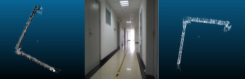
In order to evaluate the positioning accuracy and the quality of the 3D model acquired by RGB-D sensor, it is very useful to register the 3D model with the LiDAR point cloud in large scenes. This can be done by selecting distinct control points from both data sets and then transform the local map coordinates to the coordinate system of the LIDAR data. The Microsoft Kinetic RGB-D camera was used to capture the 3D data of the test environments. The RGB-D slam with extended BA was used to reconstruct the point cloud of indoor scenes which are then compared with the dense point cloud of the same scenes acquired by the high specification Rigel vz1000 terrestrial LiDAR and Velodyne mobile laser scanner. The alignment results are shown in and .
Figure 1. RGB-D 3D feature data base (left); Velodyne LiDAR of the same environment; alignment of LiDAR and RGB-D feature database.
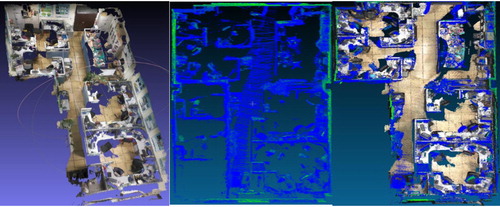
Figure 2. RGB-D 3D feature database closely aligned with Rigel vz1000 terrestrial LiDAR point cloud.
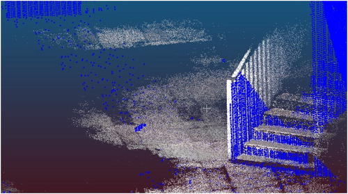
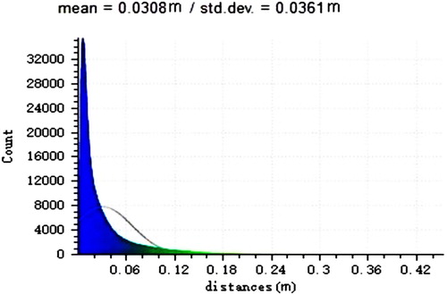
The comparative study demonstrates that the mean distance error between the two point clouds is 3.08 cm in , the fine details of the two point clouds are adequately represented and aligned closely together. Thus the developed RGB-D 3D reconstruction algorithm is highly reliable and has achieved high accuracy at centimetre level.
Figure 3. Point cloud registration error between RGB-D and LiDAR.
3. Camera localization workflow
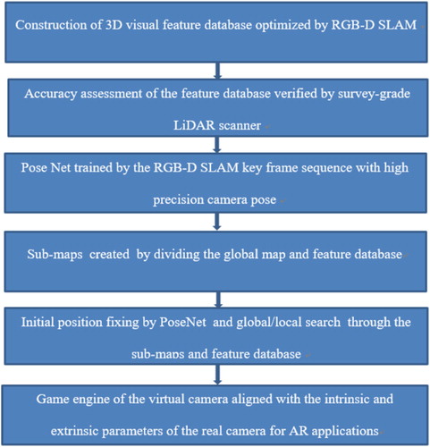
Our proposed workflow for indoor positioning is illustrated in in which the first two steps are described in the previous section. At the positioning stage, we first extract ORB feature points from a query image for camera localization and then search through the constructed feature database for ORB feature matching in either global or local (i.e. nearby) space. Once correct feature correspondences are found, the 3D coordinates for the matched feature points are retrieved from the feature database for camera pose estimation which solves the Perspective-n-Point (PnP) problem through 2D–3D correspondences (Lepetit, Moreno-Noguer, and Fua Citation2009), the RANSAC routine is then applied to remove the false correspondences and refine the camera pose which is subsequently transformed to obtain the camera position in the world coordinate system (WCS, i.e. the coordinate system used in the prior map). It should be noted that, since searching through the whole map and feature database for large-scale scenes may be time-consuming, an initial coarse position fixing based on deep learning methods is a very effective approach to fast and robust position initialization provided that the global map is split into multiple sub-maps beforehand in order to improve search efficiency. A rough estimate of the initial camera pose at metre level by deep learning can be used to quickly identify the nearest sub-map for more accurate camera pose, and this approach is also effective in camera pose reinitialization in failure mode due to the high robustness and rich feature sets provided by the deep learning method (e.g. incomplete input data and varying lighting can be accommodated). We thus adopted a Convolutional Neural Networks (CNN) model called PoseNet which is a recent novel development of deep convolutional neural networks to end-to-end 6 DOF camera pose localization (Kendall, Grimes, and Cipolla Citation2015; Kendall and Cipolla Citation2016). PoseNet model is a slightly modified version of GoogLeNet with 23 layers in which the 3 softmax classifiers are replaced with affine regressors and the fully connected layer output a 7-dimension pose (i.e. 3D position and quaternion orientation). The model takes advantage of transfer learning which trains a camera pose regressor, pre-trained as classifier on large-scale image recognition datasets. Such model converges to lower error in less time and only requires a small local training dataset to provide good localization accuracy as well as running in real-time and high robustness.
Figure 4. Proposed camera localization framework.
In this work, instead of using a collection of discrete images as training data, we explore the use of consecutive frames labelled with high precision camera pose at every camera position generated by our RGB-D SLAM algorithm, as this is more closely related to indoor positioning and AR conditions. Both training and testing were done on a Linux PC with an Intel Core i7-6700 CPU, NVIDIA GeForce GTX 1070 GPU and 16GB memory. All samples were trained using stochastic gradient descent with a base learning rate of 0.001, reduced by 90% every 80 epochs and with momentum of 0.9.
Having derived a camera pose, it is necessary to transform the camera pose to a camera position in the WCS to complete position fixing. Since camera position calculation from a camera pose is hardly described in the literature, the equations for deriving a position fix is therefore given as follows.
For example, the origin of the camera coordinate system in the WCS is , the coordinates of an object P in the WCS is thus
, vector OP in the WCS is thus
.
Then, we have(1)
(1) where R is the rotation matrix between WCS and CCS (Camera Coordinate System); OPc is the vector in CCS.
Having derived OPc, the pixel coordinate of the object P in the camera plane is then obtained by left multiplying the camera intrinsic matrix.(2)
(2) where K is the camera intrinsic matrix.
Meanwhile, the pixel coordinate of the object P can also be written as(3)
(3) where R is the rotation matrix and T is the translation matrix.
We then derive(4)
(4) where (Xc, Yc, Zc) are the camera coordinates in the WCS. R is the camera rotation matrix and T is the translation matrix.
4. Virtual and real camera alignment for AR
We next utilize the irrlicht 3D game engine to facilitate the implementation of AR applications. It should be noted that the tight coupling of high-level 3D graphics engine with vision-based positioning algorithm can facilitate the implementation of AR applications and enhance the application performance since a variety of high-level graphics APIs such as camera model, 3D model insertion, advanced rendering functions and animations are already implemented on top of the low-level OpenGL APIs. The use of the irrlicht 3D game engine is rather representative as well as being more generic than specific in current AR applications. AR objects are assigned their 3D world coordinates and placed in the scene. The developed vision based positioning algorithm calculates the real camera position (X, Y, Z) and orientation (yaw, row, pitch) in the WCS when the current image frame is taken. The internal parameters of the real camera are subsequently sent to the virtual camera provided by the game engine so that both the internal and external parameters of the real camera are the same as those in the virtual camera. As a result, the game engine calculates the 2D image of the object using the internal and external parameters from the real camera in real time to correctly position the AR objects in the video sequence. The equations for aligning a generic virtual and real camera are described as follows:
Based on the projection and viewport transformation matrix in the game engine, the screen coordinates of the 3D objects in the game engine can be descried as follows:(5)
(5) where V is the viewport matrix and P is the transformation matrix.
(6)
(6)
(7)
(7) where Zc is the Z value in the camera coordinates of the object in the game engine
, z is a screen coordinate derived from the z-axis vector of the normalized coordinates after viewport transformation. Note that this screen coordinate z is placed there purely for the convenience of matrix multiplication and thus not displayed in the game engine whereas u and v are actually used. n is z value of the near clipping plane in the camera coordinate system, (X, Y) are normally set to (0, 0), r is the maximum x value along the coordinate system of the near clipping plane on which the objects within the viewing frustum are projected, t is the corresponding y value.
is the world coordinates of the object.
is the rotation and translation matrix, Width*Height is the resolution of the image,
the maximum z value of the screen coordinates,
is the minimum z.
Meanwhile the camera model of the real world is as follows:(8)
(8)
(9)
(9) where u, v are the screen coordinates of the projected object, f is the camera focus, dx, dy are the physical pixel size in the screen coordinate system along x- and y-axes. u0, v0 the pixel value of the projection centre.
From Equations (7) and (9) where the pixel values of the projected object in the screen coordinate system are equal, we can derive(10)
(10)
(11)
(11)
(12)
(12)
(13)
(13) where n is the z value of the near clipping plane in the camera coordinate system, (X, Y) are the pixel value of the left-up corner of the image which is normally set to (0, 0) by default. r and t are the x- and y values of the furthest boundary corner point projected in the clipping plane coordinate system within the viewing frustum, width and height are the image resolution.
5. Experimental results and discussion
As shown in , the experiments were carried out on the level 3 corridor with a length of 57 m × 40 m.
Figure 5. 3D dense point cloud (left); an example frame (middle); the sparse 3D feature database (right).
Having fiddling around with the PnP RANSAC iteration count and the number of matched point pairs, demonstrates that around 200 matched pair of feature points per frame achieve the optimal accuracy in the test area. Moreover, the image frames that are more significantly different from the original feature database key frames in perspectives and lighting conditions usually require more pairs of point correspondences and iterations resulting in longer computation time.
Figure 6. Camera position accuracy for one frame.
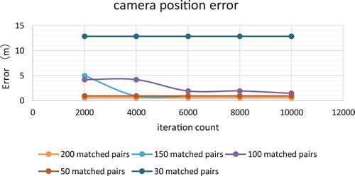
Note that the accuracy is estimated by the difference between the camera position provided by the localization method and the corresponding ground-truth camera position provided by our optimized high accuracy RGB-D SLAM track which is cross validated with LiDAR data and also went through a number of optimization techniques such as loop closure and extended BA with control points.
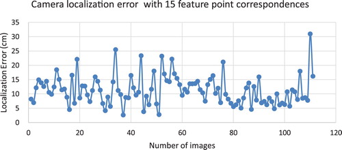
Next, we extract one image from every 50 images which were once used to generate the 3D point cloud and feature database and then perform the positioning task on each image. The results of 110 images in the test field show that 15 pairs of feature point correspondence are sufficient on every image to provide an accurate position after 600 RANSAC iterations. The mean localization error is 11 cm as shown in .
Figure 7. Camera localization error from the original image set used for constructing the 3D feature database.
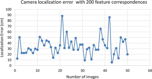
Furthermore, localization using an independent image set with varying lighting conditions and more perspective change than the original image set used at database construction stage is of practical importance in this research, because this is closer to real-life application scenarios. For this purpose, we extracted one image from every 20 images for localization from another image set collected on a different day. Note that the ground-truth data for this independent image set can be obtained by aligning the dense point cloud constructed from this independent image set with that from the ground-truth image set used for constructing the feature database and prior map using common control points. As such, the results in demonstrate that the number of required feature correspondences has increased to 200 from 15 in order to obtain an accurate camera position. The number of RANSAC iterations has also increased significantly to reject more mismatches. It can be seen from that the mean localization error has increased to 35 cm compared with which is, however, still adequate for most AR applications.
Figure 8. Camera localization error from an independent image set in the same area.
For an initial coarse camera position fix at metre level accuracy, the fast and robust deep learning method as described in the previous section was adopted.
The training data sets we use contain two indoor scenes. Every video frame has a resolution of 640 × 480 and a frame spacing ranges from 3 to 20 cm between each camera position.
To evaluate the model accuracy, we carefully selected one office and one corridor scene. – show the detailed description and the spatial extent of each testing dataset. Note that the office and corridor datasets are collected by the high precision RGB-D SLAM. The CNN localization results are shown in and .
Figure 9. Office examples.
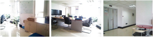
Figure 10. Corridor examples.

Figure 11. Office testing frames (left, 3.4 × 3 m) and corridor testing frames (right, 57 × 40 m).
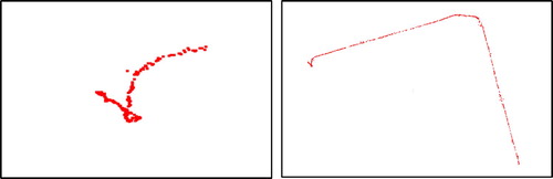
Table 1. Dataset details and results.
Table 2. Position error for all datasets.
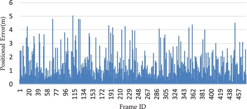
As can be seen from , and and , localization with PoseNet in smaller space generally produces less error, for example, the office data set achieved an localization accuracy of 0.65 m with a maximum error of 1.39 m in . For the larger scenes, the corridor dataset produced 1 m accuracy with a maximum error of 4.31 m as shown in . also shows good median performance (i.e. within 1 m) for the two datasets. Moreover, we reduced the density of training samples for the two scenes by half (i.e. only half of the training frames are used), and found out that the localization accuracy remains more or less the same. In general, training CNN using consecutive video frames labelled with camera pose generated by the RGB-D SLAM method demonstrated very good localization accuracy in both test scenes.
Figure 12. Position errors for the Office1 dataset.
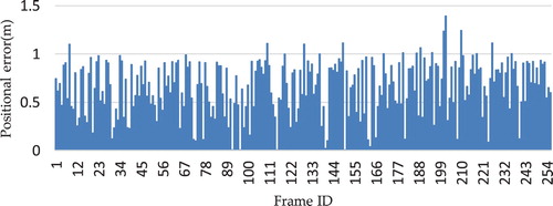
Figure 13. Position errors for the Playground dataset.
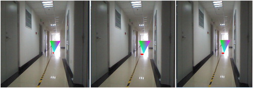
It is worthwhile to know the influence of localization accuracy on the visual effects in AR applications. demonstrates that the 8 and 1 cm localization errors do not have noticeable effect on the AR overlay. However, a 66-cm positioning error may cause a more distinct visual misalignment. As displayed in , the object in the left most image is closer to the yellow middle line than in the other two images as indicated by solid red rectangles. Thus the accuracy requirement is dependent on the type of application at hand.
Figure 14. AR overlay with 66 cm error (left), 8 cm error (middle), 1 cm error (right).
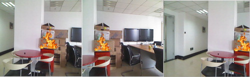
As mentioned in the previous section, the alignment of the real and virtual camera provided by the game engine, as shown in , greatly facilitates the implementation of AR applications especially in a VGE and GIS (Huang, Sun, and Li Citation2016). Having successfully aligned the Kinetic V1 camera’s internal and external parameters with the virtual camera in the irrlicht 3D game engine using the equations in the previous section, illustrates the AR fire effect in an GIS emergency response context based on the camera localization results from this research. It can be seen from that the virtual fire model appears exactly in the right place regardless of rotational and translational changes from the camera image.
Figure 15. AR overlay in the irrlicht 3D game engine.
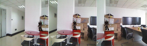
Figure 16. AR fire overlay after the real and virtual camera alignment.
6. Conclusions and future work
In this paper, we have evaluated the effectiveness and accuracy of the proposed camera localization workflow based on a prior efficient ORB 3D feature database optimized by our RGB-D SLAM method with extended BA and loop closure in the context of AR and indoor positioning. An initial fast camera position fix at metre level accuracy can be obtained by using consecutive video frames labelled with optimized high precision camera pose calculated by the RGB-D SLAM algorithm as a new source of training data for the deep convolutional neural network camera pose regressor.
Having completed a comprehensive evaluation, the experimental results show that the localization accuracy can achieve an accuracy of 11 cm (mean error) for the image set used in the map building process and 35 cm from an independent image set with varying lighting and different perspectives in the same known environment respectively. These results are all based on a fine-tuned accurate prior 3D feature database map at 3 cm accuracy compared with the ground-truth 3D LiDAR map. By taking advantage of the prior knowledge of the known environment, this level of camera localization accuracy should meet the requirements of most AR applications and indoor navigation without error accumulation. In addition, the novel workflow which incorporates the developed localization algorithm and an alignment of the real camera model with a virtual camera provided by the game engine greatly facilitates the implementation of AR applications in the field VGE and GIS as illustrated in .
In future work, the developed localization will be made more robust and efficient by integrating short-term relative positioning methods and geometric features from LiDAR and RGB-D sensor. We will further explore the potential use of CNN-based localization algorithm with depth data and geometric constraints derived from digital map for AR applications and indoor positioning. The integration of CNN-based localization with computer vision methods may also be of interest in the future.
Acknowledgements
We thank Mingjie Chen from Xi’an University of Science and Technology for his assistance with producing figures.
Disclosure statement
No potential conflict of interest was reported by the authors.
Additional information
Funding
References
- Akçayır, M., and G. Akçayır. 2017. “Advantages and Challenges Associated with Augmented Reality for Education: A Systematic Review of the Literature.” Educational Research Review 20: 1–11. doi: 10.1016/j.edurev.2016.11.002
- Behringer, R., J. Park, and V. Sundareswaran. 2002. “Model-based Visual Tracking for Outdoor Augmented Reality Applications, Mixed and Augmented Reality.” ISMAR: 277–322.
- Bleser, G., and D. Stricker. 2009. “Advanced Tracking Through Efficient Image Processing and Visual-inertial Sensor Fusion.” Computers & Graphics 33 (1): 59–72. doi: 10.1016/j.cag.2008.11.004
- Calonder, M., V. Lepetit, C. Strecha, and P. Fua. 2010. “BRIEF: Binary Robust Independent Elementary Features.” In Computer Vision – ECCV 2010. Lecture Notes in Computer Science. Vol. 6314., edited by K. Daniilidis, P. Maragos, and N. Paragios, 778–792. Berlin, Heidelberg: Springer.
- Di, K., Q. Zhao, W. Wan, Y. Wang, and Y. Gao. 2016. “RGB-D SLAM Based on Extended Bundle Adjustment with 2D and 3D Information.” Sensors 16 (8): 1285–1299. doi: 10.3390/s16081285
- Dine, A., A. Elouardi, B. Vincke, and S. Bouaziz. 2016. “Graph-based Simultaneous Localization and Mapping: Computational Complexity Reduction on a Multicore Heterogeneous Architecture.” IEEE Robotics & Automation Magazine 23 (4): 160–173. doi: 10.1109/MRA.2016.2580466
- Gavrila, D. M., U. Franke, C. Wohler, and S. Gorzig. 2001. “Real Time Vision for Intelligent Vehicles.” IEEE Instrumentation & Measurement Magazine 4: 22–27. doi: 10.1109/5289.930982
- Huang, W., M. Sun, and S. Li. 2016. “A 3D GIS-based Interactive Registration Mechanism for Outdoor Augmented Reality System.” Expert Systems with Applications 55: 48–58. doi: 10.1016/j.eswa.2016.01.037
- Jo, D., and G. J. Kim. 2016. “ARIoT: Scalable Augmented Reality Framework for Interacting with Internet of Things Appliances Everywhere.” IEEE Transactions on Consumer Electronics 62 (3): 334–340. doi: 10.1109/TCE.2016.7613201
- Kendall, A., and R. Cipolla. 2016. Modelling Uncertainty in Deep Learning for Camera Relocalization, 4762–4769. Stockholm: Robotics and Automation (ICRA).
- Kendall, A., M. Grimes, and R. Posenet Cipolla. 2015. “A Convolutional Network for Real-time 6-d of Camera Relocalization.” Proceedings of the IEEE International Conference on computer vision, Chile, December 7–13, 2938–2946.
- Lepetit, V., F. Moreno-Noguer, and P. Fua. 2009. “EPnP: An Accurate O(n) Solution to the PnP Problem.” International Journal of Computer Vision 81 (2): 155–166. doi: 10.1007/s11263-008-0152-6
- Li, J., H. Bao, X. Han, F. Pan, W. Pan, F. Zhang, and D. Wang. 2017. “Real-time Self-driving car Navigation and Obstacle Avoidance Using Mobile 3D Laser Scanner and GNSS.” Multimedia Tools & Applications 76 (21): 23017–23039. doi: 10.1007/s11042-016-4211-7
- Li, J., and X. Fan. 2015. “Outdoor Augmented Reality Tracking Using 3D City Models and Game Engine.” International Congress on Image and Signal Processing, IEEE: 104–108.
- Rameau, F., H. Ha, K. Joo, J. Choi, K. Park, and I. S. Kweon. 2016. “A Real-time Augmented Reality System to See-through Cars.” IEEE Transactions on Visualization and Computer Graphics 22 (11): 2395–2404. doi: 10.1109/TVCG.2016.2593768
- Raúl, Mur-Artal, J. M. M. Montiel, and Juan D. Tardós. 2015. “ORB-SLAM: A Versatile and Accurate Monocular SLAM System.” IEEE Transactions on Robotics 31 (5): 1147–1163. doi:10.1109/TRO.2015.2463671.
- Rehman, U., and S. Cao. 2017. “Augmented-Reality-based Indoor Navigation: A Comparative Analysis of Handheld Devices Versus Google Glass.” IEEE Transactions on Human-Machine Systems 47 (1): 140–151.
- Reitmayr, G., and T. Drummond. 2006. “Going Out: Robust Model-based Tracking for Outdoor Augmented Reality.” Proceedings of International Symposium on Mixed and Augmented Reality: 109–118.
- Schönberger, Johannes Lutz, and Jan-Michael Frahm. 2016. “Structure-from-Motion Revisited.” IEEE Conference on Computer Vision and Pattern Recognition 2016: 4104–4113.
- Taketomi, T., T. Sato, and N. Yokoya. 2008. “Real-time Camera Position and Posture Estimation Using a Feature Landmark Database with Priorities.” International Conference on Pattern Recognition, IEEE: 1–4.
- Taketomi, Takafumi, Tomokazu Sato, and Naokazu Yokoya. 2011. “Real-time and Accurate Extrinsic Camera Parameter Estimation Using Feature Landmark Database for Augmented Reality.” Computers & Graphics 35 (4): 768–777. ISSN 0097-8493. doi: 10.1016/j.cag.2011.04.007
- Wagner, D., G. Reitmayr, A. Mulloni, T. Drummond, and D. Schmalstieg. 2010. “Real-Time Detection and Tracking for Augmented Reality on Mobile Phones.” IEEE Transactions on Visualization and Computer Graphics 16 (3): 355–368. doi: 10.1109/TVCG.2009.99