
 ?Mathematical formulae have been encoded as MathML and are displayed in this HTML version using MathJax in order to improve their display. Uncheck the box to turn MathJax off. This feature requires Javascript. Click on a formula to zoom.
ABSTRACT
Simultaneous Localization and Mapping (SLAM) has been widely used in emergency response, self-driving and city-scale 3D mapping and navigation. Recent deep-learning based feature point extractors have demonstrated superior performance in dealing with the complex environmental challenges (e.g. extreme lighting) while the traditional extractors are struggling. In this paper, we have successfully improved the robustness and accuracy of a monocular visual SLAM system under various complex scenes by adding a deep learning based visual localization thread as an augmentation to the visual SLAM framework. In this thread, our feature extractor with an efficient lightweight deep neural network is used for absolute pose and scale estimation in real time using the highly accurate georeferenced prior map database at 20cm geometric accuracy created by our in-house and low-cost LiDAR and camera integrated device. The closed-loop error provided by our SLAM system with and without this enhancement is 1.03m and 18.28m respectively. The scale estimation of the monocular visual SLAM is also significantly improved (0.01 versus 0.98). In addition, a novel camera-LiDAR calibration workflow is also provided for large-scale 3D mapping. This paper demonstrates the application and research potential of deep-learning based vision SLAM with image and LiDAR sensors.
1. Introduction
A monocular visual Simultaneous Localization and Mapping (SLAM) system has been widely used in mobile augmented reality, self-driving, robotics, unmanned aerial vehicle, emergency response, city-scale 3D mapping and navigation (Fan, Kong, and Zhang Citation2021; Guo et al. Citation2021). This is owing to the fact that SLAM has the ability to locate the moving platform itself as well as mapping the surrounding environments in real-time. Furthermore, a single camera is easy to implement a monocular visual SLAM at low cost especially on low powered mobile devices although a monocular vision SLAM is more prone to scale errors and disturbances from surrounding environments. However, it should be noted that robustness and reliable feature point extraction from images lie at the heart of the modern SLAM systems.
Recent deep-learning based feature point extractors have demonstrated superior performance in dealing with the real-world complex environmental challenges (e.g. extreme lighting change, texture-less and repeated texture scenes) while the traditional image feature points-based SLAM systems (e.g. the most advanced ORB SLAM3) are struggling especially in the context of city-scale navigation and 3D reconstruction.
In this research, we extend our previous work (Shi et al. Citation2022) on an improved lightweight deep neural network with knowledge distillation for local feature extraction through the integration of deep-learning based feature extractor with the existing monocular vision SLAM framework
More specifically, the original contributions of this research are as follows:
A monocular visual SLAM system is developed by adding enhancement to the state-of-the-art ORB-SLAM3. This is done by adding an additional deep-learning based visual localization thread to the existing visual SLAM framework. In this added thread, our local image feature extractor, based on our efficient lightweight deep neural network (Shi et al. Citation2022) and a highly accurate prior map database, are used to estimate the absolute camera pose and the scale in real-time for the purpose of eliminating long-term accumulation error and registering all the segmented sub-maps in the SLAM system to the same geographic coordinate system for large-scale 3D modeling and navigation.
Furthermore, we designed and developed an in-house LiDAR-camera integrated device at a cost of around 3000 U.S dollars. A novel LiDAR-camera calibration workflow is then developed by a combination of using checkboard and targetless methods in outdoor scenes in order to build a centimeter accuracy prior map which contains deep learning-based local image feature points, its descriptors and the corresponding LiDAR 3D points. A LiDAR-vision integrated SLAM system is also developed to produce large-scale 3D maps at centimeter accuracy in real-time.
A comprehensive performance evaluation of the proposed SLAM system in terms of accuracy and robustness is provided under the conditions of rapid illumination changes, weak texture, and repeated texture scenes in the following sections.
2. Related work
2.1. Deep local features
In the field of computer vision and photogrammetry, identification of the stable and reliable image feature points plays a key role in most visual tasks, such as face recognition, visual localization, Structure from Motion (SfM), and Simultaneous Localization and Mapping (SLAM). However, up until now, in the tasks of visual localization and SLAM, feature point extraction still faces many challenges due to the complex environmental conditions such as illumination change, weak texture and repeated texture. As with the prevalence of deep learning, many learning-based feature points have emerged. These feature points have achieved excellent performance in feature matching even in challenging environments. For example, SuperPoint (DeTone, Malisiewicz, and Rabinovich Citation2018) and UnsperPoint (Hviid Christiansen et al. Citation2019) both use a Fully-Convolutional Network (FCN) architecture with two prediction heads to predict key points and descriptors respectively. D2-Net (Dusmanu et al. Citation2019) adopts transfer learning method and uses a public dataset including abundant SfM models to fine tune a deep neural network pre-trained on ImageNet dataset (Deng et al. Citation2009). Moreover, considering the running efficiency of feature extraction, HF-Net (Sarlin et al. Citation2019) reduce the scale of deep local feature extraction network by using the inverted residual blocks from MobileNet V2 (Sandler et al. Citation2018). More recently, Shi et al. (Citation2022) adopts knowledge distillation, and use a teacher network and the ground truth labels from a public dataset concurrently to train the built lightweight network.
2.2. Monocular visual SLAM
MonoSLAM (Davison et al. Citation2007) is the first real-time monocular visual SLAM system, which uses extended Kalman filter as the back-end and tracks the sparse feature points in the front-end. Subsequently, the first keyframe-based monocular visual SLAM system, PTAM (Klein and Murray Citation2007), was proposed, and it is also the first SLAM system using nonlinear optimization method as the back-end. It adopts a parallel strategy of tracking and mapping for the first time and improve the tracking efficiency significantly. ORB-SLAM (Mur-Artal, Montiel, and Tardós Citation2015) extends the parallelization framework of PTAM and divide the system into three parallel threads: tracking, local mapping and loop closure. It performs feature matching and re-localization based on ORB feature points (Rublee et al. Citation2011), and uses loop detection and closure mechanisms to eliminate cumulative errors. The above monocular visual SLAM systems can only use a single camera to realize real-time pose estimation and mapping, but they all have the problem of scale drift and lack of absolute coordinate reference in real world, which is unsuitable for continuous 3D visualization and navigation in large outdoor scenes. Therefore, multiple sensor fusion has become a research hotspot for monocular visual SLAM. For example, VINS-Mono (Qin, Li, and Shen Citation2018) and ORB-SLAM3 (Campos et al. Citation2020) both use cheap inertial measurement unit (IMU) for accurate scale estimation, but IMU may not work in the state of slow and uniform motion due to the lack of effective acceleration; VINS-Fusion (Qin and Shen Citation2018; Qin et al. Citation2019) uses global navigation satellite system (GNSS) to obtain absolute localization information, but the accuracy is poor in the condition of no GNSS signals. Our developed monocular SLAM system can solve the above problems of monocular SLAM only by using a low-cost monocular camera with a prior map built by our in-house LiDAR and camera integrated device.
2.3. Extrinsic calibration of LiDAR and camera
A highly accurate prior map can be built using LiDAR and RGB camera sensors. In the simultaneous acquisition of LiDAR point clouds and RGB images, accurate joint calibration of different sensors is required to unify the data under different sensor coordinate systems. The current calibration methods are mainly classified as external target-based and targetless. Gong, Lin, and Liu (Citation2013) used the geometric constraints of the prevalent trihedral structure objects to calculate the external parameters to iteratively optimize the nonlinear least squares problem Further improving the calibration accuracy. Zhou, Li, and Kaess (Citation2018) introduced 3D line correspondence into the original planar correspondence to reduce the number of minimum calibration plate poses required for calibration. Target-based calibration methods often require additional calibration plates, which are simple but cumbersome to operate and less applicable in various dynamic scenarios. In contrast, the targetless calibration method does not depend on external objects, and is able to make external parameters corrections at each data acquisition time. Liu and Zhang (Citation2021) estimate external features from the sensor motion and optimize them with appearance information. The new solid-state LiDAR is capable of providing dense point cloud information, whereby Yuan et al. (Citation2021) propose a new method for calibrating high-resolution LiDARs and cameras using depth-edge features of natural objects in a targetless environment, which shows consistency, accuracy and robustness in both indoor and outdoor environments, and can even achieve pixel-level calibration accuracy under optimal conditions.
2.4. LiDAR SLAM
Once the spatial placement of a camera and a LiDAR sensor is known through the calibration methods described above in 2.3, a LiDAR SLAM system is usually required to generate a continuous sequence of aligned image and point cloud frames. For the purpose of completeness, a few popular LiDAR SLAM systems pertinent to the LiDAR SLAM used in this work are briefly introduced here. Note that we do not intent to develop a new LiDAR SLAM but utilize the existing methods to construct the prior map database in order to enhance a monocular visual SLAM system.
LiDAR provides accurate ranging information of the external environments with relatively constant errors, and the use of LiDAR sensors and the simultaneous localization and mapping method is one of the main means of current 3D mapping. In LiDAR SLAM systems LiDAR is often coupled with IMU to eliminate the motion distortion of laser points and improve the accuracy of LiDAR odometry (Ye, Chen, and Liu Citation2019). LOAM is a classical algorithm for LiDAR SLAM, which extracts edge and plane feature points from point clouds and constructs an error function to solve the nonlinear optimization problem of positional (Zhang and Singh Citation2014). This work also pre-integrates the IMU data to obtain a priori poses, thus realizing a loosely coupled algorithm between LiDAR and IMU. However, LOAM does not have loop detection and global optimization modules (Xu et al. Citation2022), which makes it difficult to eliminate the accumulated errors generated by the odometer. In order to reduce the long-term error, many works aimed to improve and refine this, such as LeGO-LOAM (Shan and Englot Citation2018) and Loam-livox (Lin and Zhang Citation2020). Moreover, the LiDAR SLAM algorithm with tight coupling to IMU has also emerged, using sliding windows to maintain and optimize the LiDAR and IMU measurements, thus improving the algorithm accuracy, but the algorithm has high time complexity and is difficult to run in real time. LIO-SAM uses factor maps in odometry to achieve tight coupling to IMU measurements and uses local map matching instead of global matching to improve the real-time performance of the algorithm, but the algorithm is less reliable in large outdoor scenes and prone to degradation and other problems (Shan et al. Citation2020).
3. Methodology
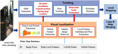
The architecture of our proposed monocular visual SLAM system is demonstrated in . The main enhancement to a typical monocular visual SLAM system (i.e. the classic ORB-SLAM3 is chosen in this work) is that we added a visual localization thread incorporating the deep local feature extractor discussed in (Shi et al. Citation2022) and a highly accurate prior LiDAR-image feature map database into the ORB-SLAM3 system. The added visual localization thread firstly uses a lightweight deep neural network to extract local features of an image, then extracts global image feature to retrieve similar images from a pre-constructed prior map database at centimeter locational accuracy. This highly accurate prior LiDAR-image feature map database is built by our newly designed in-house and low-cost LiDAR-camera integrated device on which the camera and LiDAR sensors are first calibrated and aligned, and then a camera-LiDAR SLAM system run in real-time along with the deep local feature extractor and RTK GNSS control points. The resultant prior LiDAR-image feature map database is thus composed of the corresponding 3D LiDAR point coordinates of the image feature point, the 2D image coordinates of the image feature point, image No of the image feature point and our deep-learning based feature descriptor of the image feature point. By searching through this prior LiDAR-image feature map, the added visual localization finally performs local feature matching and pose estimation to obtain the absolute pose of the query image in real world. Put it simply, this new thread feeds accurate absolute image poses, which is obtained by matched 2D feature points on the query image and the most similar image from the LiDAR-image feature prior map database, into the tracking thread of ORB-SLAM3 so that absolute coordinate transformation from the camera coordinate system to the geographic coordinate system can be achieved whenever ORB SLAM3 initializes a new map duo to the loss of tracking. As a result, all the sub-maps created by this monocular visual SLAM are merged into one whole map within the same spatial reference frame. Furthermore, a monocular scale estimation method is also integrated into pose tracking to improve mapping and localization accuracy as shown in . The visual localization method in our framework is described in detail in our previous work (Shi et al. Citation2022). The following subsections describes each step in more details.
Figure 1. Architecture of the developed monocular visual SLAM system.
3.1. Sensors calibration
To build a prior map database containing the image feature points and the corresponding 3D LiDAR points along with the deep local feature descriptors, we need to use the calibrated and aligned LiDAR sensor and RGB camera to acquire laser point cloud frame and image frame
simultaneously. The LiDAR point cloud is used in the LiDAR SLAM system to calculate the sensor pose state and build a geometrically accurate prior map database, while the image sequence precisely aligned with the LiDAR point clouds is used to extract deep local feature points and store their corresponding deep local feature descriptors into the prior map database. Here, the novel part of this work is that we take a two-step LiDAR-camera calibration approach which first uses a checkboard method and then further refines the calibration results by a targetless approach. The calibration details are explained as below:
The camera's internal parameters can be obtained by calibrating the camera, and the external parameters
can be obtained by jointly calibrating the camera and LiDAR to convert the laser point 3D coordinates
in the LiDAR coordinate system to the 3D coordinates
in the camera coordinate system, then the LiDAR's pose matrix
in the world coordinate system and the camera's positional matrix
can be converted by the following equation:
(1)
(1) In the two-dimensional plane of the image
corresponds to the point coordinates of
,
,
,
and
are the internal parameters of the camera, and
and
are the rotation matrix and translation vector of the coordinate transformation, respectively. Then the pixel points on the image can be converted to the LiDAR coordinate system by the following equations:
(2)
(2)
(3)
(3)
(4)
(4)
The above process is able to obtain the positional state of the RGB camera during motion and the transformation relationship between the LiDAR coordinate system and the image pixel coordinate system, but it places high demands on the accuracy of the external parameters of the sensors. After accurate calibration of the camera internal parameters using the checkerboard calibration method, we designed and developed a LiDAR and camera integrated device to collect data from the checkerboard calibration board and manually select a series of matching laser points and image pixel points from the corner points of the calibration board to solve for the device external parameters using the above equation. At least six pairs of matching points are generally required to linearly solve for the external parameters, and the least-squares optimization of the target equations is performed using the Levenberg-Marquardt algorithm (LM algorithm) to find the optimal rotation matrix and translation vectors.
When using the calibration plate to calibrate the external parameters of the sensor, the calibration plate is usually placed closer to the sensor. However, in large outdoor scenes, small calibration errors can be magnified at long distances, causing mis-matching of the laser point cloud with the image. Therefore, we also adopt a targetless calibration method based on depth-continuous features (Yuan et al. Citation2021), which extracts uniformly distributed edge structures in natural scenes and minimizes reprojection errors to achieve high accuracy calibration results in both indoor and outdoor scenes. Since the method requires a feature rich calibration scene to achieve pixel-level calibration, we use the target-based calibration results as the initialization parameters of the targetless calibration method to reduce the edge feature matching errors and the computation time of the algorithm optimization, thus reducing the dependence of the on-site high-precision calibration results on the feature rich scene.
3.2. Prior map construction
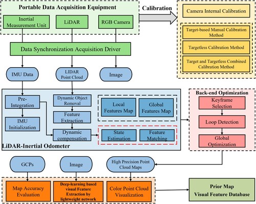
In order to establish a highly accurate prior map, we use the LIDAR-Inertial tightly coupled SLAM algorithm, which is divided into two modules: LIDAR-Inertial Odometer (LIO) and Back-end Optimization. The algorithm workflow is shown in .
We use the open source project LIO-LivoxFootnote1 to calculate the motion state and pose information of the sensors. The advantage of this LiDAR odometer is that it is designed for outdoor dynamic scenes with the goal of robustness. Its dynamic target removal, the use of irregular features and other characteristics ensure the accuracy and reliability of the LiDAR odometer. The odometer also applies the maximum posteriori estimation (MAP) to the initialization process of IMU, and uses the sliding window method to implement the tight coupling between LIDAR and IMU.
Although the odometer can calculate the pose information of each frame of data and build a point cloud map, there still are many problems in the complex outdoor environments, such as too few feature points leading to odometer degradation and cumulative errors caused by long-time operation. We use loop detection and graph optimization methods to solve the above problems. In order to reduce the computational complexity of the back-end optimization module, we select key frames for loop detection and global optimization from a series of laser point cloud frames. These key frames are selected according to the number of feature points in the point cloud and the distance, angle offset and interval frames of adjacent frames. We use the Scancontext point cloud descriptor for scene recognition and loop detection of laser point clouds (Kim and Kim Citation2018), so as to make efficient use of the distribution characteristics of point clouds in large outdoor scenes. When the loop is identified, the back-end optimization module will relocate and use the GTSAM (Georgia Tech Smoothing and Mapping) factor graph toolbox to perform global map optimization, which effectively improves the global consistency of the prior map and reduces the cumulative error caused by the LiDAR odometer.
Figure 2. Workflow of building prior map using LiDAR SLAM method.
3.3. Absolute coordinate transformation
It should be noted that a visual SLAM system such as ORB-SLAM3 will normally reinitialize and regenerate a new map (i.e. a sub-map) when tracking fails. Because each sub-map is located in a local coordinate reference with (0,0,0) as the coordinate origin, no one consistent coordinate reference exits between multiple sub-maps. Only when revisiting a scene, the sub-maps with independent coordinate references are fuzed. This way of initializing new maps is more suitable for applications such as robots in a local coordinate frame, but for positioning, navigation and 3D reconstruction in geospatial coordinate frame, the mutually independent coordinate references between sub-maps are not usable. Therefore, when creating a new map, our SLAM system uses the absolute pose information provided by the visual localization thread to transform the initial key frames and map points into the coordinate reference where the prior map is located. In this way, the coordinate references between different maps are always consistent even without map fusion.
We input monocular video stream into the ORB-SLAM3 and visual localization thread. ORB-SLAM3 obtains the pose of two initial keyframes and
according to epipolar constraint, where the pose of the first initial keyframe
is the identity matrix. According to the covisibility of the two initial frames, the initial map points
can be obtained. Let the absolute pose of the first initial key frame calculated by the visual localization thread be
, then the absolute pose
corresponding to
is expressed by the formula as follows:
(5)
(5) The absolute pose
corresponding to
is expressed by the formula as follows:
(6)
(6)
The absolute coordinate of initial map point is calculated by the formula as follows:
(7)
(7)
3.4. Monocular scale estimation
Based on the absolute pose information provided by the visual localization thread described above, we only use monocular video stream to estimate the scale. It should be noted that our proposed method has more advantages compared to using inertial navigation unit (IMU) for scale estimation:
only monocular camera is used for scale estimation, which is cheaper;
more accurate scale can be obtained in the state of slow and uniform motion, in which IMU may not work due to the lack of effective acceleration.
For a certain time, we note the coordinate of current camera center point calculated by ORB-SLAM3 as , the distance from
to the map origin coordinate
as
. The coordinate of current camera center point calculated by visual localization thread is noted as
, and its error is noted as
. Let the distance between
and O be
, then the scale
can be estimated by the following formula:
(8)
(8) As can be seen from the formula, the larger
is, the smaller the influence of
on the accuracy of estimated scale is. Therefore, in our SLAM system, the scale estimation is performed after passing N frames and only when
is in increasing state, thus reducing the impact of visual localization error on the accuracy of scale estimation.
4. Experiments
4.1. Design and calibration LiDAR and RGB camera integrated device
4.1.1. Data acquisition equipment
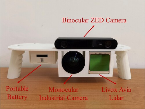
We used the sensors as shown in as the experimental equipment, the Livox Avia LiDAR sensor and Hikvision industrial camera are used to collect aligned laser point clouds and images for prior map and visual feature database construction. A ZED binocular camera is also used to collect video sequence data from the same viewpoint for cross-modal visual localization experiments. The chosen LiDAR sensor in this work is a relatively new type of solid-state LIDAR using a rotating mirror scanning method, which outperforms the traditional mechanical rotating line-scan LiDAR in terms of portability, cost, and reliability under certain conditions. It has excellent long-range detection capability with a range of 450 meters, and can output 240,000 high-precision point clouds per second while maintaining a field of view of 70.4° (horizontal) x 77.2° (vertical), with a range accuracy of 2 cm, and a built-in IMU sensor (BMI088 model). The Hikvision industrial camera is capable of capturing color images with a resolution of 2560*2048. Since the field of view of the LiDAR is smaller than that of a traditional mechanical rotating line-scan LIDAR, the Hikvision industrial camera was fitted with a camera lens with a similar field of view to the LiDAR sensor, thus ensuring an effective match between the laser point cloud and the image. The supporting plastic platform in white color is made by a 3D printer.
Table 1. Sensor devices used in the experiments.
Considering the portability and small field of view of the chosen LiDAR sensor, we decided to combine these sensors into a handheld data acquisition device that is able to acquire data flexibly in complex outdoor scenes according to the mapping needs at hand. The device was designed using solid modeling software and the prototype of the device, shown in , was created using 3D printing techniques. The ZED binocular camera was also fixed to the device to facilitate the acquisition of visual data from the same viewing angle. The above sensors are connected to a mobile power source and a laptop with an i5-8300H installed with Ubuntu Linux. The LiDAR sensor and the industrial camera acquire data at a frame rate of 10 and 30 Hz respectively, and the data collection and processing are software-triggered using each sensor driver. To guarantee a stable frame rate for image data acquisition, we downsample the images to 1280*1024 resolution and store them in a local file on the computer and use the ROS program to preview the laser point cloud and compressed images in real time. After experimental verification, the software-triggered data acquisition method can achieve a time synchronization error of less than 30 ms between different sensors without adding additional time synchronization circuit boards and trigger lines.
Figure 3. Handheld data acquisition device with LIDAR and RGB camera combination.
4.1.2. Extrinsic calibration of LiDAR and camera
After completing the design and integration of the data acquisition equipment, we calibrated the external parameters of the LiDAR and camera using a checkerboard calibration board and a depth-continuous feature-based targetless calibration method, respectively. To verify the calibration accuracy for the outdoor application scene, we statically acquired LiDAR point clouds and one image for about 20 s and projected the point cloud onto the image to generate colored point clouds, as displayed in . With the image-like high resolution colored laser point clouds, we can visually evaluate the accuracy of the calibration results. Although the calibration method based on the checkerboard calibration plate performs well in the close view, the projection error between the point clouds and the image gradually increases with increasing distance, which greatly affects the visualization effect. Comparison and close inspection of the local detail maps show the effect of using more accurate initial parameters on the targetless method. We evaluated the performance of these three methods using the projection error of the laser point cloud versus the image at 50 m and the spent algorithm time, and the results in the demonstrate that the combination of the targetless and targeted methods can achieve centimeter-level calibration results in a shorter period of time. We notice that anomalous colored point clouds often appear around the tree contours where the laser may shoot through the leaf gap. In the longer period of static acquisition, the tree branches are also be affected by the wind swaying movement so that the point clouds and the color images do not always match correctly.
Figure 4. Diagram of the calibration effect of the three methods.
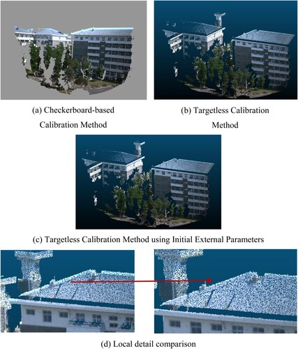
Table 2. Accuracy and time efficiency of calibration results.
4.2. Data collection and prior map construction
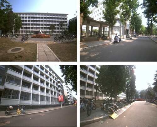
We chose the campus scene shown in as the experimental site for prior map construction and visual localization. In this scene, there are a large number of dynamic targets, such as pedestrians, bicycles, and vehicles, and there is also dense vegetation that can block the field of view of the camera, so the robustness and stability of the LiDAR SLAM algorithm in complex environments are very demanding. In this work, we adopted the opensource Robust LiDAR-Inertial Odometry for Livox LiDAR, we walked 273 meters around the building with the developed in-house LiDAR and camera integrated device, collecting data on the building and its surrounding objects, and then returned to the starting position at the end of the data collection to verify the closed-loop error of the trajectory. We also collected two sets of data, the first dataset for prior map and visual feature database construction, and the second dataset to be used for accuracy evaluation of the ORB-SLAM3 augmented by our visual localization algorithm. In the first data acquisition, we tried to move as smoothly as possible to reduce motion blur caused by violent jitter to the camera imaging and to improve the accuracy of the LiDAR map construction. In the second acquisition we also acquired ZED binocular camera video sequence from the same viewpoint. In addition, we acquired several GNSS ground control points in the area using centimeter accuracy RTK equipment to verify the accuracy of the prior map construction.
Figure 5. Experimental site for data acquisition.
and demonstrate the accuracy evaluation results of the prior map construction in the campus scene. The accuracy of the 3D map constructed using the LiDAR-Inertial SLAM algorithm is around 20 cm, and the trajectory loop closure error reaches centimeter level. After using loopback optimization, the overall accuracy of the map construction was improved by 49.8%, and the translation error was reduced by 60.9%. This accuracy can meet the accuracy requirements of the prior map construction for the purpose of visual localization in various real-world applications such as emergency response and self-driving, thus proving the feasibility of the developed method of constructing prior maps for visual localization using an in-house and low-cost solid-state LiDAR and camera integrated device.
Figure 6. Colored LiDAR prior map.
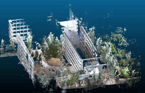
Table 3. Geometric accuracy of the prior map.
4.3. Visual localization evaluation
Since the feature matching performance plays a paramount role in many modern SLAM and 3D construction systems, we evaluate the feature matching performance of the local feature points extracted by our lightweight network over a set of continuous image frames, as well as the recall rate (i.e. the success rate) and accuracy of visual localization.
4.3.1. Feature matching for continuous image frames
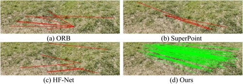
For the feature points extracted by our lightweight network, we evaluate the matching performance of continuous frames under three extreme conditions: rapid illumination changes, weak texture and repeated texture. The evaluation results reflect the potential application environments of our monocular visual SLAM system to a certain extent. We choose traditional feature points such as ORB and deep feature point extracted by deep neural network such as SuperPoint and HF-Net, to compare with our feature point.
As shown in , when the light is suddenly turned on in a dark corridor, our feature points can be perfectly matched while others all exhibits matching errors highlighted in red lines. This is because our lightweight feature extraction network is distillated by the teacher network D2-Net and inherits the excellent performance of D2-Net against illumination changes. As shown in , under the condition of weak texture such as white wall, our feature points can still be extracted and matched well, while ORB can't be effectively extracted at all and neither SuperPoint nor HF-Net can match correctly. This is due to the fact that our lightweight network adopts a detect-then-describe approach for local feature extraction, which utilizes the high-level information of the network. Thus, our feature points are more insightful and stable. As shown in , in the repeated texture scene of grass, our feature points match well, mainly because our feature points adopt floating-point descriptors with higher dimension (512 dimension), which is more distinguishable.
Figure 7. Comparison of feature matching effects under the condition of rapid illumination changes.
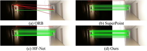
Figure 8. Comparison of feature matching effects under the condition of weak texture.
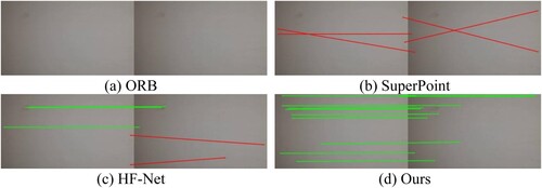
Figure 9. Comparison of feature matching effects under the condition of repeated texture.
4.3.2. Localization recall and accuracy evaluation
We use a HKRobot camera and a Livox LiDAR to collect aligned images and LiDAR point cloud around the dormitory buildings on campus, and then build a prior map database and a verification dataset according to the method (Shi et al. Citation2022), where the prior LiDAR-image feature map database and verification dataset are generated from the data collected at different time periods during the day. To achieve the real-time performance in our SLAM system, the global feature extraction and similar image retrieval from constructed prior map database in the visual localization thread use DBoW3 to replace NetVLAD and nearest neighbor (NN) search method (Shi et al. Citation2022). In addition, we also use ZED camera to collect image data along the same route of HKRobot camera to verify the cross- modal performance of our visual localization. For an image frame, we consider its estimated pose is valid if the number of inliers of pose estimation is greater than 6. The localization recall is defined as the percentage of the number of image frames with valid pose estimation to the total number of image frames, and the localization accuracy is defined as the mean error between the estimated poses and the real poses provided by constructed verification dataset for all image frames with valid pose estimation.
shows the evaluation results of localization recall for HKRobot camera and ZED camera. HkRobot camera achieves a high localization recall because the images captured by the same HkRobot camera are stored in the prior map database; ZED camera achieves the localization recall of 57.53%, which indicates that our visual localization algorithm is partially capable of cross-modal localization. shows the evaluation results of the localization accuracy of the HKRobot camera. The mean translation error is 0.55 meters and the mean rotation error is 1.4 degrees, which can satisfy the requirements of absolute pose transformation and monocular scale estimation.
Table 4. Evaluation results of localization recall for HKRobot camera and ZED camera.
Table 5. Evaluation results of localization accuracy for HKRobot camera.
4.4. Evaluation of SLAM methods
Walking around the dormitory buildings on campus, we use the HKRobot camera to collect the monocular video stream, and ensure that the starting point and ending point of the camera route are at the same position, so as to conveniently calculate the closed-loop error. Meanwhile, we use GNSS RTK to collect 250 ground point coordinates at less than 5 cm localization accuracy on the camera route, and calculate the true length L of the route to be 273.33 meters, which is then used to calculate the scale error. Let the length of the route obtained by running monocular SLAM be , then the scale error can be calculated by the formula as follows:
(9)
(9) The closer
is to 1, the smaller the scale drift. If
is greater than 1, the scale is enlarged; If
is less than 1, the scale is reduced. Let the starting and ending point coordinate calculated by monocular SLAM to be
and
respectively, then the closed-loop error is calculated by the formular as the follows:
(10)
(10) where ||*|| is L2 vector norm.
(a) shows a single map obtained by running monocular ORB-SLAM3. (b) shows multiple maps obtained by running monocular ORB-SLAM3. It can be seen that the coordinate reference of each sub-map is independent, and the route of each sub-map takes the coordinate origin as the starting point. (c) shows multiple sub-maps obtained by running our monocular visual SLAM system. It can be seen that each map has a consistent coordinate reference and all three sub-maps are registered to the same coordinate reference frame. shows the evaluation results of the two SLAM systems. Compared with monocular ORB-SLAM3, ours has almost no scale drift. The closed-loop error of our monocular SLAM system is only 1.03 meters, which is significantly smaller than that of monocular ORB-SLAM3. The significant accuracy improvement in scale estimation and loop closure is mainly because our SLAM system uses the accurate pose information provided by newly added visual localization thread when creating maps and scale estimation, thus reducing the accumulation error.
Figure 10. Result of SLAM.
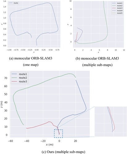
Table 6. Evaluation results of SLAM.
5. Conclusion and discussion
In conclusion, recent deep-learning based feature point extractors have demonstrated great potential in dealing with the real-world complex environmental challenges (e.g. extreme lighting change, texture-less and repeated texture scenes) while the traditional vision SLAM are struggling to cope with especially in city-scale navigation, 3D reconstruction, emergency response, self-driving and augmented reality. Building upon our previous work (Shi et al. Citation2022), We have successfully improved the robustness and accuracy of a monocular visual SLAM system by adding an additional efficient deep learning based visual localization thread as an augmentation to the traditional SLAM framework. In this added thread, our robust and efficient local feature extractor based on a lightweight deep neural network is used for absolute pose and scale estimation in real time using the highly accurate georeferenced prior map database created by our in-house low-cost LiDAR-camera integrated device. The close loop error with and without this enhancement is 1.03 and 18.28 m respectively as shown in . The scale estimation of the monocular visual SLAM is also significantly improved (1.01 versus 0.02 shown in ). In addition, we designed and developed our own low-cost and real-time LiDAR-camera integrated device at a cost of about 3000 U.S. dollars. The resultant prior LiDAR-image feature map database created by this device in real-time includes deep learning-based local image feature points extracted by a lightweight neural network, its descriptors and the corresponding LiDAR 3D points. The geometric accuracy of this prior map output by the developed LiDAR SLAM algorithm is around 20 cm as shown in . It can be seen from this research that the integration of deep-learning based feature extractor with existing monocular vision SLAM framework opens up more research and market opportunities due to improved robustness in dealing with environmental challenges, higher 3D mapping and localization accuracy and more intelligence. In the future, we will aim to develop a tightly coupled LiDAR-camera SLAM system based on the proposed deep local feature point extractor.
Disclosure statement
No potential conflict of interest was reported by the author(s).
Data availability statement
Due to the nature of this research, participants of this study did not agree for their data to be shared publicly, so supporting data is not available.
Additional information
Funding
Notes
References
- Campos, Carlos, Richard Elvira, Juan J. Gómez Rodríguez, José M. M. Montiel, and Juan D. Tardós. 2020. “ORB-SLAM3: An Accurate Open-Source Library for Visual, Visual-Inertial and Multi-Map SLAM.” arXiv:2007.11898.
- Davison, A. J., I. D. Reid, N. D. Molton, and O. Stasse. 2007. “MonoSLAM: Real-time Single Camera SLAM.” Ieee Transactions on Pattern Analysis and Machine Intelligence 29 (6): 1052–1067. doi:10.1109/TPAMI.2007.1049.
- Deng, J., W. Dong, R. Socher, L. J. Li, Li Kai, and Fei-Fei Li. 2009. “ImageNet: A Large-scale Hierarchical Image Database.” Paper presented at the 2009 IEEE Conference on Computer Vision and Pattern Recognition, June 20–25.
- DeTone, D., T. Malisiewicz, and A. Rabinovich. 2018. “SuperPoint: Self-Supervised Interest Point Detection and Description.” In Proceedings 2018 Ieee/Cvf Conference on Computer Vision and Pattern Recognition Workshops (Cvprw), 337–349. doi:10.1109/Cvprw.2018.00060.
- Dusmanu, M., I. Rocco, T. Pajdla, M. Pollefeys, J. Sivic, A. Torii, and T. Sattler. 2019. “D2-Net: A Trainable CNN for Joint Description and Detection of Local Features.” In 2019 Ieee/Cvf Conference on Computer Vision and Pattern Recognition (Cvpr 2019), 8084–8093. doi:10.1109/Cvpr.2019.00828.
- Fan, H., G. Kong, and C. Zhang. 2021. “An Interactive Platform for Low-cost 3D Building Modeling from VGI Data Using Convolutional Neural Network.” Big Earth Data 5 (1): 49–65. doi:10.1080/20964471.2021.1886391.
- Gong, Xiaojin, Ying Lin, and Jilin Liu. 2013. “3D LIDAR-camera Extrinsic Calibration Using an Arbitrary Trihedron.” Sensors 13 (2): 1902–1918.
- Guo, H., D. Liang, F. Chen, and Z. Shirazi. 2021. “Innovative Approaches to the Sustainable Development Goals Using Big Earth Data.” Big Earth Data 5 (3): 263–276. doi:10.1080/20964471.2021.1939989.
- Hviid Christiansen, Peter, Mikkel Fly Kragh, Yury Brodskiy, and Henrik Karstoft. 2019. “UnsuperPoint: End-to-end Unsupervised Interest Point Detector and Descriptor.” arXiv:1907.04011.
- Kim, Giseop, and Ayoung Kim. 2018. “Scan Context: Egocentric Spatial Descriptor for Place Recognition Within 3d Point Cloud map.” Paper presented at the 2018 IEEE/RSJ International Conference on Intelligent Robots and Systems (IROS).
- Klein, G., and D. Murray. 2007. “Parallel Tracking and Mapping for Small AR Workspaces.” Paper presented at the 2007 6th IEEE and ACM International Symposium on Mixed and Augmented Reality, November 13–16.
- Lin, Jiarong, and Fu Zhang. 2020. “Loam Livox: A Fast, Robust, High-Precision LiDAR Odometry and Mapping Package for LiDARs of Small FoV.” Paper presented at the 2020 IEEE International Conference on Robotics and Automation (ICRA).
- Liu, Xiyuan, and Fu Zhang. 2021. “Extrinsic Calibration of Multiple Lidars of Small FoV in Targetless Environments.” IEEE Robotics and Automation Letters 6 (2): 2036–2043.
- Mur-Artal, R., J. M. M. Montiel, and J. D. Tardós. 2015. “ORB-SLAM: A Versatile and Accurate Monocular SLAM System.” IEEE Transactions on Robotics 31 (5): 1147–1163. doi:10.1109/TRO.2015.2463671.
- Qin, Tong, Shaozu Cao, Jie Pan, and Shaojie Shen. 2019. “A General Optimization-based Framework for Global Pose Estimation with Multiple Sensors.” arXiv:1901.03642.
- Qin, T., P. Li, and S. Shen. 2018. “VINS-Mono: A Robust and Versatile Monocular Visual-Inertial State Estimator.” IEEE Transactions on Robotics 34 (4): 1004–1020. doi:10.1109/TRO.2018.2853729.
- Qin, T., and S. Shen. 2018. “Online Temporal Calibration for Monocular Visual-Inertial Systems.” Paper presented at the 2018 IEEE/RSJ International Conference on Intelligent Robots and Systems (IROS), October 1–5.
- Rublee, E., V. Rabaud, K. Konolige, and G. Bradski. 2011. “ORB: An Efficient Alternative to SIFT or SURF.” In 2011 International Conference on Computer Vision, 2564–2571. doi:10.1109/ICCV.2011.6126544.
- Sandler, Mark, Andrew Howard, Menglong Zhu, Andrey Zhmoginov, and Liang-Chieh Chen. 2018. “MobileNetV2: Inverted Residuals and Linear Bottlenecks.” In 2018 IEEE/CVF Conference on Computer Vision and Pattern Recognition, 4510–4520. doi:10.1109/cvpr.2018.00474.
- Sarlin, Paul-Edouard, Cesar Cadena, Roland Siegwart, and Marcin Dymczyk. 2019. “From Coarse to Fine: Robust Hierarchical Localization at Large Scale.” In 2019 IEEE/CVF Conference on Computer Vision and Pattern Recognition (CVPR), 12708–12717. doi:10.1109/cvpr.2019.01300.
- Shan, Tixiao, and Brendan Englot. 2018. “Lego-loam: Lightweight and Ground-Optimized Lidar Odometry and Mapping on Variable Terrain.” Paper presented at the 2018 IEEE/RSJ International Conference on Intelligent Robots and Systems (IROS).
- Shan, Tixiao, Brendan Englot, Drew Meyers, Wei Wang, Carlo Ratti, and Daniela Rus. 2020. “Lio-sam: Tightly-Coupled Lidar Inertial Odometry via Smoothing and Mapping.” Paper presented at the 2020 IEEE/RSJ International Conference on Intelligent Robots and Systems (IROS).
- Shi, Chenhui, Jing Li, Jianhua Gong, Banghui Yang, and Guoyong Zhang. 2022. “An Improved Lightweight Deep Neural Network with Knowledge Distillation for Local Feature Extraction and Visual Localization Using Images and LiDAR Point Clouds.” ISPRS Journal of Photogrammetry and Remote Sensing 184: 177–188. doi:10.1016/j.isprsjprs.2021.12.011.
- Xu, Xiaobin, Lei Zhang, Jian Yang, Chenfei Cao, Wen Wang, Yingying Ran, Zhiying Tan, and Minzhou Luo. 2022. “A Review of Multi-Sensor Fusion SLAM Systems Based on 3D LIDAR.” Remote Sensing 14 (12): 2835.
- Ye, Haoyang, Yuying Chen, and Ming Liu. 2019. “Tightly Coupled 3d Lidar Inertial Odometry and Mapping.” Paper presented at the 2019 International Conference on Robotics and Automation (ICRA).
- Yuan, Chongjian, Xiyuan Liu, Xiaoping Hong, and Fu Zhang. 2021. “Pixel-level Extrinsic Self Calibration of High Resolution Lidar and Camera in Targetless Environments.” IEEE Robotics and Automation Letters 6 (4): 7517–7524.
- Zhang, Ji, and Sanjiv Singh. 2014. “LOAM: Lidar Odometry and Mapping in Real-time.” Paper presented at the Robotics: Science and Systems.
- Zhou, Lipu, Zimo Li, and Michael Kaess. 2018. “Automatic Extrinsic Calibration of a Camera and a 3d Lidar Using Line and Plane Correspondences.” Paper presented at the 2018 IEEE/RSJ International Conference on Intelligent Robots and Systems (IROS).