
ABSTRACT
Electrospun cyclodextrin (CD)-based nanofibers with capabilities to remove pollutants from water have been synthesized and characterized. The high-quality nanofibers presented here were synthesized in two simple steps that involved in-situ electrospinning of the nanofibers and all nanocomponents, followed by the reduction of silver (Ag+) and iron (Fe3+) ions to nanoparticles using an environmentally benign process that involved irradiation of the electrospun fibers using a tailor-made UV-equipped furnace at low temperatures. In the previously reported study it was observed that Ag and Fe nanoparticles effectively removed a range of different strains of Gram-negative and Gram-positive bacteria from water. As such, this study focused on improving the thermal and mechanical properties of the nanofibers prepared from polymer blends of β-CDs with cellulose acetate (CA) and small additions (2 wt%) of functionalized multiwalled carbon nanotubes (f-MWCNTs). The electrospinning parameters were varied to determine the optimum conditions for preparation of uniform non-beaded nanofibers. Bead-free and uniform nanofibers were obtained at a polymer concentration of 32% at the ratio of 1:1 β-CDs:CA, syringe injection flow rate of 0.7 mL h−1, 15 cm between the tip of the spinneret and the collector, and a voltage of 16 kV. The addition of f-MWCNTs was found to improve the tensile strength of the nanofibers by twofold, relative to nanofibers with no f-MWCNTs. The thermal degradation of the nanofibers was improved by a magnitude of 50°C. The study has shown that adding small amounts of f-MWCNTs improved the thermal stability and mechanical strength of the CD/CA nanofibers significantly.
Introduction
The synthesis of cyclodextrin (CD) polymers for use in environmental applications has received significant interest in the past decade [Citation1,Citation2]. These materials have been made in various forms (mainly powders and beads) [Citation3,Citation4] which have been shown to remove various organic, metallic, and microbial pollutants from water. However, several challenges have been reported that relate to the scale at which the materials can be produced and the costs associated with them. Typical synthesis methods that have been used include grafting and copolymerization which involved the use of toxic solvents (linkers) such as toluene 2,4-diisocyanate (TDI). Recently, Mphahlele et al. synthesized β-CD-based nanocomposite materials under environmentally friendly microwave irradiation [Citation5]. The materials formed were powder and these tend to form slurry after multiple uses. Another viable option is to use the electrospinning technique to synthesize the β-CD-based nanofibers which provides larger surface area as well as stability toward specific intended use.
The CDs consist of six, seven, and eight glucopyranose units and they are known as α-CDs, β-CDs, and γ-CDs, respectively [Citation6]. β-CDs are less soluble compared to α-CDs and γ-CDs and they have medium molecular weight which is between that of α-CDs and γ-CDs. Thus, it can be modified/blended with other polymers to provide the suitable property needed for electrospinning. β-CDs are also less expensive than α-CDs, γ-CDs, and other derivatized CDs (). Therefore, they are the best candidates for the synthesis of CD-based nanofibrous composites.
Table 1. Natural CDs and their derivatives that can be found in market surveys [Citation7].
β-CDs are known to be soluble in water and their electrospun nanofibrous materials produce highly electrosprayed beaded nanofibers. Electrospraying and the formation of beads on electrospun β-CD nanofibers are caused by the low molecular weight (MW) and the viscosity of the β-CD polymers. In electrospinning, smooth nanofibers are not obtained until the critical polymer concentration/viscosity and MW have been attained. At low viscosity, the molecular entanglement becomes poor which leads to the formation of beaded nanofibers [Citation8]. On the other hand, polymer MW manifests the entanglement and intertwinement of the polymer chains as well as the elongation of the whole polymer chain between the collecting plate and the spinneret [Citation9]. Polymer entanglement, intertwinement, and elongation improve with an increase in polymer MW, which leads to the formation of non-beaded nanofibers. At low polymer MW, entanglement and stretching of the polymer become very poor. This leads to the polymer stream break up, hence formation of highly electrosprayed and beaded nanofibers, which are not desired [Citation10]. Thus, β-CDs require immobilization onto polymers with higher MW to overcome the aforementioned problems.
Cellulose acetate (CA), which is a derived ester of cellulose, is regarded as the suitable material to immobilize β-CD and produce nanofibers with good morphology. CA is usually prepared from the reaction of cellulose, acetic acid, and acetic anhydride in the presence of sulfuric acid catalyst to yield cellulose triacetate [Citation11]. The cellulose triacetate is then hydrolyzed in a mixed solvent system of water, acetic acid, and/or toluene to obtain a specific degree of substitution [Citation11]. Cellulose is the most abundant polysaccharide obtained from the cell wall of green plants [Citation12]. The abundance of cellulose defines the ease of accessibility and low cost of its products [Citation12]. CA is also known to have high thermal and mechanical properties and numerous chelating groups [Citation13].
However, further improved functional properties such as thermal, mechanical, and antibacterial activities of the β-CD- and CA-based nanofibers could be achieved on addition of nanomaterials including carbon nanotubes (CNTs) and silver (Ag) and iron (Fe) nanoparticles (NPs) [Citation14,Citation15]. CNTs are cylindrical nanostructured allotropes of carbon. Owing to their thermal and mechanical properties, CNTs are used as additives in many applications [Citation16]. Ag and Fe NPs are metallic nanostructured materials and they have gained consideration in microbiological treatment due to their strong biocidal properties [Citation17,Citation18].
The nanofibrous materials produced from these polymers can be prepared using a range of techniques such as (a) air-blast atomization of mesophase pitch, (b) pulling of non-polymer molecules by an atomic force microscope tip, (c) laser-assisted catalytic growth, and (d) electrospinning [Citation19,Citation20]. Most of these techniques are known to produce nanofibers with diameters above 1000 nm, which is far beyond the defined nanometer scale in nanoscience and nanotechnology [Citation21]. However, the electrospinning technique was found to be a suitable technique to produce nanofibers with diameters in the range of the nanometer scale [Citation22]. CNTs [Citation23] and Ag and Fe NPs [Citation24] used as additives to improve mechanical, thermal, and biocidal properties of intended materials can be synthesized using material fabrication techniques such as chemical vapor deposition [Citation25] and UV irradiation [Citation14], respectively.
Nanofibers of β-CDs and CA have found applications in filtration systems, medical and pharmaceutical industries, lamination, enzyme immobilization, and adsorption media [Citation13]. In the previous study, it was demonstrated that β-CDs and CA nanofibers embedded with Ag and Fe NPs are capable of removing bacteria from water [Citation14]. Despite the inherent properties observed from these biopolymers, further studies need to be conducted to improve their properties such as thermal and mechanical strength. In this work, small quantities of multiwalled CNTs (MWCNTs) were added to the electrospun β-CD/CA nanofibers decorated with Ag and Fe NPs to improve their thermal and mechanical strength and to produce uniform and non-beaded β-CD/CA nanofibers.
Experimental
Materials
β-CD (MW = 1134.98 g mol-1), CA (39.8 wt% acetyl, MW = 30,000 g mol-1), iron(III) chloride (FeCl3), acetone, and N,N-dimethyl acetamide (DMAc) were purchased from Sigma Aldrich (Munich, Germany). Silver nitrate (AgNO3) was purchased from Rochelle Chemicals (Johannesburg, South Africa). De-ionized water was prepared in our laboratory using Direct-Q® (Millipore) system supplied by Merck Millipore (Johannesburg, South Africa). MWCNTs were synthesized and purified/oxidized as described in the next section. All chemicals and reagents were used as received.
Synthesis and purification of MWCNTs
MWCNTs with average diameter of 30 nm were synthesized following the procedure reported by Mhlanga et al. [Citation26]. They were purified using a mixture of H2SO4 and HNO3. This involved transferring 0.2 g of the as-synthesized MWCNTs into a 25 mL solution of sulfuric acid/nitric acid mixture (3:1) in a 100 mL round-bottom flask equipped with a condenser. The contents of the flask were refluxed at 120ºC for 24 h. The resulting mixture was diluted with 1000 mL of de-ionized water and filtered. The rinsing was repeated until the filtrate was at neutral pH. The oxidized MWCNTs were dried in an oven at 110ºC for 48 h. The dry oxidized MWCNTs shall henceforth be referred to as functionalized MWCNTs (f-MWCNTs).
Preparation of electrospinning solution
The concentration of β-CDs was varied to obtain the critical viscosity/concentration required to prepare an electrospinnable solution of β-CDs. β-CD powders were transferred to a clean beaker and dried in the oven at 70ºC for 24 h and cooled in a desiccator in order to exclude the atmospheric moisture. The β-CD solutions (60–80%) were prepared by weighing 6, 8, 10, 12, 14, and 16 g of β-CD and transferred into six 50 mL round-bottom flasks fitted with a condenser. Acetone/DMAc mixed solvents (10 mL at the ratio of 3:2) was added into each flask containing the β-CD powder. The contents of the flasks were stirred for 24 h and centrifuged for 3 min at 78,000 rpm to remove the suspended particles. The resulting solutions were then decanted into the clean glass bottles and were ready for electrospinning.
β-CD/CA solution
β-CD was blended with CA at different ratios to improve its electrospinnability. β-CD:CA (1:4, 1:3, 1:2, 1:1, and 2:1 ratios) solutions were prepared at a total polymer concentration of 32%. The blended polymer solutions were centrifuged for 3 min at 78,000 rpm. The prepared solutions were then transferred into glass bottles and were ready for electrospinning.
Blending of electrospinnable polymer solutions with f-MWCNTs
To prepare nanofibers with 2 wt% f-MWCNTs, 4 mg of the f-MWCNTs was added to 0.2 g total mass in a round-bottom flask. The contents of the flask were stirred at 50ºC for 24 h to achieve a homogeneous mixture. The resulting solutions were ready for electrospinning.
Blending of electrospinnable polymer solutions with Ag+ and Fe3+
To prepare the polymer solution containing 2 wt% of Ag+ and Fe3+, the precisely calculated mass of silver nitrate (0.0064 g) and iron(III) chloride (0.012 g) were added to mix with 0.2 g total mass of β-CD/CA in a round-bottom flask. The contents of the flask were stirred at 50ºC for 24 h to achieve a homogeneous mixture. The resulting solutions were ready for electrospinning.
Electrospinning of the polymer solutions
The prepared solutions were transferred to a 10 mL plastic syringe fitted with a needle of 0.8 mm internal diameter. The syringe was placed on a NE-4000 double syringe pump. A high-voltage generator was used to induce an electric field between the collecting plate and the tip of the needle. The positive terminal of the DC generator was connected to the tip of the syringe needle and the negative terminal was connected to the aluminium foil (collecting plate). The earth terminals were connected to the syringe pump. The electrospinning conditions were varied until the optimum conditions were obtained, i.e. injection flow rate, distance between syringe and the collector, and the voltage of the generator. The following electrospinning parameters were varied to determine the conditions that produced nanofibers with good morphology: (a) the voltage applied (varied from 9 to 27 kV), (b) the distance between the tip of the needle and the collecting plate (varied from 12 to 27 cm), and (c) the solution flow rate (varied from 0.3 to 1.2 mL h−1).
Cross-linking of nanofibers
The electrospun nanofibers were dried in an oven at 60ºC for 24 h to remove moisture. The β-CD/CA nanofibers were placed in a mixture of sodium hydride (NaH) and succinic anhydride (SA) at β-CD:NaH:SA ratio of 1:2:1. The mixture was gently stirred at 60ºC for 24 h. The nanofibers were subsequently washed three times with acetone and dried in an oven for 24 h.
Reduction of Ag and Fe metal ions
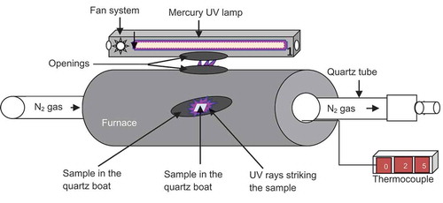
The electrospun β-CD/CA nanofibers embedded with Ag+ and Ag+/Fe3+ ions were reduced using a non-toxic chemical approach wherein they were irradiated with UV light at max = 249 nm using a 420 W Hg lamp fitted in a horizontal furnace (). The reduction of the metal ions into NPs was carried out at 70ºC in the presence of ammonia gas to enhance the photochemical reduction of the metal ions to NPs. The nanofibers were irradiated at different times from 30 to 210 min to determine the effect of the irradiation time on the intensity of NPs dispersed on the surface of nanofibers.
Figure 1. The experimental setup for the UV-assisted reduction of Ag and Ag/Fe NPs supported on β-CD/CA nanofibers.
Results and discussion
Scanning electron microscopy (SEM) analysis
Optimization of β-CD polymer concentrations
The concentration of β-CDs was varied to obtain the critical viscosity/concentration required to prepare electrospinning β-CD solutions. At a polymer concentration of 60–120%, there was no observable electrospinning. White aqueous droplets were drawn toward the collecting plate by the electric field and were observed to immediately stream down the collecting plate. This was attributed to failure to attain intrinsic viscosity at these concentrations as well as low molecular weight of β-CDs [Citation8]. At 140% of β-CDs, the formation of nanofibers was accompanied by electrospraying which is known to occur when the viscosity/concentration of the electrospun polymer is below the critical viscosity/concentration or the molecular weight is below the limit required for molecular entanglement and fiber formation ()) [Citation27]. However, as the concentration of the β-CDs was increased to 160%, the electrospinning solution became too viscous and could not be pumped out of the syringe.
Figure 2. The SEM images of β-CD nanofibers synthesized at different concentrations of β-CDs: (a) 140% β-CD and (b) 32% polymer concentration of β-CD:CA at the ratio of 1:4.
To overcome this challenge, while maintaining the saccharide backbone of the nanofibers, the β-CDs were then blended with CA. At 32% concentration of β-CD/CA (β-CD:CA ratio of 1:4), the electrospraying was reduced but the nanofibers were still highly beaded ()). The formation of the beaded nanofibers was associated to different factors that affect electrospinning such as voltage [Citation28], distance between the tip of the spinneret and the collector [Citation29], the polymer concentration [Citation30], solution viscosity [Citation27], and polymer molecular weight [Citation10]. The ratio of β-CD:CA was then optimized to prepare the non-beaded nanofibers.
Optimization of the ratio of β-CD/CA blended polymers
The ratio of β-CD:CA was varied while total polymer concentration was kept at 32%. The increase in the amount of β-CD relative to CA was considered advantageous since β-CD was the polymer of interest due to its inherent properties [Citation26,Citation27]. The number of beads formed concurrently with the nanofibers were found to be reduced significantly when the ratio of β-CD:CA was changed to 1:3, 1:2, and 1:1 (–)).
Figure 3. SEM images of 32% β-CD/CA nanofibers at different blending ratios: (a) β-CD:CA = 3:1, (b) β-CD:CA = 2:1, (c) β-CD:CA = 1:1, and (d) β-CD:CA = 1:2.
Since the β-CDs were observed to induce electrospraying at concentrations lower than 40%, the effect of polymer ratios of β-CD:CA 1:3, 1:2, and 1:1 was associated to the change in concentration of CA. At a β-CD:CA ratio of 1:1, the nanofibers were observed to have the least formation of beads ()). Further alteration of polymer ratio to 2:1 increased the amount of beads formed concurrently with the nanofibers. These phenomenal changes in polymer concentration, which affected the morphology of the nanofibers due to variation in solution viscosity and conductivity, are shown in . This suggested that the minimum concentration/viscosity of the polymers at the optimum ratios was a key solution to the formation of free beaded nanofibers [Citation31,Citation32]. Thus, a β-CD:CA ratio of 1:1 was the characteristic polymer ratio that assisted in the stabilization of the bending of the jet in the electric field, thus allowing the molecular entanglement for the fiber formation. As such, the β-CD:CA ratio of 1:1 was chosen as the optimum ratio and used to further optimize other electrospinning parameters since the nanofibers obtained at this ratio were observed to have fewer beads as compared to other ratios.
Table 2. Properties of the electrospun nanofibers and their corresponding nanofiber morphologies.
Effect of electrospinning parameters (flow rate, distance, and voltage) on the diameter of the β-CD/CA nanofibers
The injection flow rate of the polymer solution was varied from 0.3 to 1.2 mL h−1. The SEM images and the corresponding size distribution graphs are shown in ). The diameters of the nanofibers were found to be 166 ± 67, 238 ± 108, 430 ± 214, 540 ± 245, and 545 ± 262 nm when the injection flow rate was varied from 0.3, 0.5, 0.7, 0.9, and 1.2 mL h−1, respectively. As the flow rate was increased, it increased the amount of polymer solution ejected at a specific given time, thus resulting in the simultaneous increase in the diameters of the nanofibers ().
Table 3. The effect of electrospinning parameters on the size of the nanofibers.
Figure 4. SEM images of β-CD/CA nanofibers and the corresponding size distribution graphs of the nanofibers obtained at optimum electrospinning conditions: (a) flow rate = 0.7 mL h−1, (b) distance = 15 cm, and (c) voltage = 14 kV.
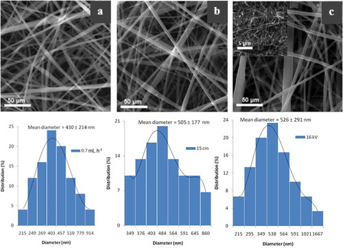
The size distributions of the nanofiber diameters were found to be non-uniform at all flow rates. Several conditions were associated to the observed non-uniform size distribution which included the inside diameter of the needle and the charge distribution on the polymer jet [Citation33]. At flow rates of 0.3 and 0.5 mL h−1, the polymer jet was found to cut several times due to the amount of insufficient polymer solution injected to be stretched by the electric field. Thus, an injection flow rate 0.7 mL h−1 was chosen to be the optimum flow rate for electrospinning of the β-CD/CA nanofibers.
The effect of the distance between the tip of the needle and the collecting plate on the nanofibers diameters was studied ()). The diameters of the nanofibers were found to be 642 ± 318, 641 ± 313, 586 ± 198, 505 ± 177, 475 ± 181, and 412 ± 154 nm at the distance of 6, 9, 12, 15, 18, and 21 cm, respectively (). The decrease in nanofiber diameters when the distance between the tip of the spinneret and the collector was increased was due to increased time of flight of the jet and the stretching effect on the polymer jets [Citation29]. The polymer jets were observed to undergo several breakups at distances of 18 and 21 cm. This phenomenon could be due to induction of weak electric field as the distance between the tip of the needle and the collector was increased while voltage was kept constant [Citation28], or the polymer viscoelasticity that failed to sustain stretching effect of the polymer jet [Citation8]. Fifteen centimeter was then chosen as the optimum distance between the tip of the spinneret and the collector since there was no stream breakup and it resulted in nanofibers with smaller diameters as compared to other distances below 15 cm.
When the voltage was varied while other parameters were kept constant, there was no observable effect on the diameter of the β-CD/CA nanofibers (). However, at 10 and 12 kV, the nanofibers became beaded. The amount of beads was greatly reduced at 14 kV. When the voltage was increased to 18–20 kV, the number of beads formed were increased ()). This could be due to the different whipping and vibrations of the polymer jet as the electric field stretched the polymer solution. However, the beads formation was less intense at 16 kV compared to other voltages. In this case, 16 kV was chosen as the optimum voltage for the formation of β-CD/CA nanofibers. Hence, 16 kV was used for subsequent preparation of non-woven fiber mats.
SEM of cross-linked β-CD/CA nanofibers containing metal NPs and CNTs
shows SEM micrographs of non-cross-linked and cross-linked β-CD/CA nanofibers containing Ag and Fe NPs and functionalized multiwalled carbon nanotubes (f-MWCNTs). The non-cross-linked nanofibers were characterized by uniform non-woven structures ()). Cross-linking with SA, the morphology of the nanofibers was retained, but some structural deformations were observed ()). When comparing the non-cross-linked and the cross-linked nanofibrous mats, the non-cross-linked nanofibers did not have fusion of neighboring nanofiber strands while the cross-linked nanofibers had fusion of neighboring nanofibers due to the chemical reaction between the β-CD on one strand of nanofiber to the other strand by SA. The metal NPs could not be seen on SEM but could be seen with transmission electron microscopy (TEM).
Figure 5. SEM images of β-CD/CA nanofibers containing (a) non-cross-linked nanofibers and (b) cross-linked nanofibers.
Fourier transform infrared (FTIR) spectroscopy analysis
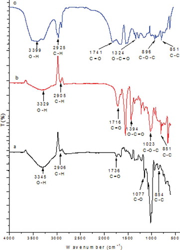
The characteristic vibrational frequencies that correspond to β-CD/CA and β-CD/CA/f-MWCNT nanofibers were recorded at 200–4000 cm–1. The FTIR spectra of the aforementioned nanofibers are shown in . The peaks at 3345, 2906, 1736, 1077, and 854 cm–1 correspond to the O–H stretching, C–H stretching, C=O bending, C–O stretching, and C–C vibrations, respectively ()). The peaks at 3329, 2905, 1716, 1394, 1023, and 851 cm–1 correspond to O–H stretching, C–H stretching, C=O stretching, O–C=O stretching, C–O–C stretching, and C–C vibration, respectively ()). The peaks at 3399, 2925, 1741, 1324, 896, and 851 cm–1 correspond to O–H stretching, C–H bending, C=O stretching, O–C=O stretching, C–O–C stretching, and C–C vibrations, respectively ()). The appearance of the peaks in the spectra confirmed the presence of functional groups of the blended polymers. The successful incorporation of the SA cross-linker was due to nucleophilic addition of the electron-rich hydroxyl groups from β-CD to the electron-deficient carbon on SA ().
Figure 6. FTIR spectra of β-CD/CA/f-MWCNT nanofibers: (a) β-CD/CA blend, (b) β-CD/CA blend cross-linked with SA, and (c) β-CD/CA/f-MWCNT cross-linked SA.
Raman analysis of β-CD/CA/f-MWCNTs
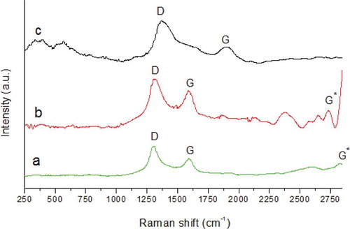
Oxidation of the as-synthesized MWCNTs with acid reduced the impurities and increased the graphitic nature of the MWCNTs. The distortion (D) and graphitic (G) bands of the f-MWCNTs were found to shift to higher frequencies when f-MWCNTs were used as fillers in the synthesis of β-CD/CA nanofibers (). This was due to disentanglement and dispersion of the f-MWCNTs in the bulk of the polymer matrix [Citation34]. presents the ratio of intensities of the D band and the G band. When the f-MWCNTs were used as fillers in the β-CD-based nanofibers, the ID/IG ratio increased from 1.25 to 3.06. This implied that the β-CD and CA polymers induced grain boundaries and interfered with the C–C vibrations of the f-MWCNTs.
Table 4. The ID/IG ratios of β-CD/CA nanofibers filled with f-MWCNTs.
Figure 7. Raman spectra: (a) as-synthesized MWCNTs, (b) f-MWCNTs, and (c) β-CD/CA/f-MWCNT nanofiber blends.
TEM analysis
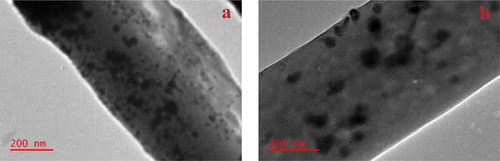
The TEM images indicated the successful embedment of the Ag and Ag/Fe NPs on the surface of the nanofibers (). The NPs were observed on the surface of the nanofibers after photochemical reduction of the respective metal ions of these NPs dispersed on the β-CD/CA nanofibers. It is believed that during photochemical reduction, the migration of the Ag+ and Fe3+ ions is activated on the surface of the nanofibers, which leads to the aggregation of these ions to be reduced while on the surface of the nanofibers [Citation35]. The Ag NPs were rather agglomerated on the surface of the nanofibers compared to the well-distributed Ag/Fe NPs. This indicated that the presence of the Fe NPs assisted in the distribution of the Ag NPs.
Figure 8. TEM images showing the distribution of the (a) Ag NPs and (b) Ag/Fe NPs on the surface of the nanofibers.
Thermogravimetric analysis
The thermogravimetric analysis (TGA) thermograms of β-CD/CA and β-CD/CA/f-MWCNTs/Ag/Fe nanofibers are presented in . The weight loss and the corresponding derivatives of the nanofibers prepared from β-CD/CA, β-CD/CA/f-MWCNTs, and β-CD/CA/f-MWCNTs/Ag/Fe occurred in a number of steps. The thermal degradation of β-CD/CA was observed to take place in four steps. The mass loss (2%) at 45–120°C was due to evaporation of the moisture absorbed in the cavities of the β-CD and the surface of the nanofibers. The second mass loss (24%) observed at 124–173°C was assigned to the depolymerization and decomposition of β-CD monomers. The third mass loss (37%) observed at 200–322°C was associated to the further decomposition of macrocycles of β-CD and CA. The last mass loss (17%) at 370–425°C was due to complete degradation of the polymers [Citation36].
Figure 9. Thermal degradation of β-CD/CA-based nanofibers and their corresponding derivatives.
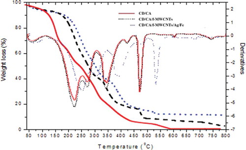
The thermal degradation of β-CD/CA/f-MWCNTs occurred in five thermal degradation steps. The first mass loss (3%) at 45–100°C was due to the evaporation of water bound in the β-CD/CA/f-MWCNT nanofibers. The second mass loss (44%) observed at 175–284°C corresponds to the depolymerization and degradation of polymer monomers. The third mass loss (18%) was observed at 330–376°C corresponding to the decomposition of macrocycles of the β-CD. The fourth mass loss (6%) observed at 463–491°C was associated to the complete degradation of the polymers. The last mass loss (2%) was observed at 721–800°C due to the decomposition of f-MWCNTs.
The thermal degradation of CD/CA/f-MWCNTs/Fe/Ag nanofibers also occurred in five steps. The degradation curve was observed to be similar to that of β-CD/CA/f-MWCNTs with the degradation temperatures slightly higher at most mass losses. Addition of small quantities of f-MWCNTs and Ag and Fe NPs to the β-CD/CA was observed to radically improve the thermal degradation of the β-CD/CA nanofibers and this observation was associated to the thermally stable nature of MWCNTs and the metallic NPs.
X-ray diffraction (XRD) analysis
The presence of MWCNTs and Ag and Fe NPs in the β-CD-based nanofibers was confirmed by XRD analysis. shows the XRD patterns f-MWCNTs, β-CD/CA/f-MWCNTs, β-CD/CA/Ag, and β-CD/CA/Ag/Fe. The Joint Committee on Powder Diffraction Standards (JCPDS) card values for the planes (003) and (101) at 2-theta = 25.89° and 43.33° are characteristics diffractions of MWCNTs ().
Figure 10. XRD patterns of (a) f-MWCNTs, (b) β-CD/CA/f-MWCNTs, (c) β-CD/CA/Ag, and (d) β-CD/CA/Ag/Fe.
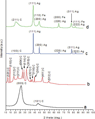
The JCPDS card values for the planes (101), (110), (112), (211), (004), (114), (310), (321), (116), (314), (411), and (512) at 2-theta = 11.41°, 13.97°, 18.12°, 22.92°, 23.07°, 27.07°, 31.56°, 36.61°, 37.77°, 39.46°, 41.97°, and 52.02°, respectively, are characteristic diffractions of carbon allotropes ()) [Citation37,Citation38]. The β-CD/CA/Ag nanofibers showed characteristics diffractions of Ag NPs at planes (111), (200), (220), (311), and (222) corresponding to 2-theta = 38.28°, 44.49°, 64.75°, 77.79°, and 81.92°, respectively, according to the JCPDS card values ()).
However, the diffractions patterns of Ag NPs shifted to 2-theta = 38.19°, 44.39°, 64.58°, 77.57°, and 81.73° on the same JCPDS values on addition of Fe (). This was due to the chemical surrounding of Ag NPs that was affected by the addition of the Fe NPs, which in turn resulted in change in shape, size, and electron density of the NPs [Citation39]. The shift could also be attributed to the extended defects and the microstrains of the peak shapes and widths of the NPs since NPs with the diameter less 100 nm are known to have defects on their surface [Citation40]. The diffractions at 2-theta = 20.44° in ) and 2-theta = 21.84° in ) were associated to the C allotropes in the nanofibers.
Tensile strength tests
shows the stress and elongation graphs of the β-CD/CA nanofibers and the effect of addition of f-MWCNTs on the strength of the nanofibers.
Figure 11. Tensile stress and elongation graphs showing the effect of addition of f-MWCNTs on β-CD/CA nanofibers: (a) β-CD/CA nanofibers and (b) β-CD/CA/f-MWCNT nanofibers.
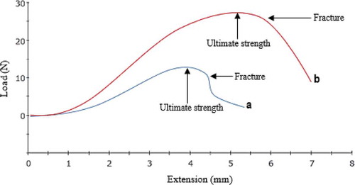
The maximum load of the β-CD/CA nanofibers was found to be 13.43 N. Addition of small quantities (2 wt%) of f-MWCNTs to the nanofibers was found to increase the maximum load to 29.64 N (). The increase in strength of the nanofibers was attributed to the strength of the f-MWCNTs. β-CD/CA and β-CD/CA/f-MWCNT nanofibers showed fracture at 13.21 and 23.42 N, respectively (). However, further stretching of the nanofibers showed maintenance of the stress beyond the fracture point, which showed that the nanofibers were not brittle.
Table 5. The effect of addition of f-MWCNTs on the tensile strength of β-CD/CA nanofibers.
Conclusion
β-CD/CA nanofibers were successfully synthesized using the electrospinning technique. The morphology and size of the nanofibers were found to highly depend on the processing parameters such as polymer concentration, distance between the tip of the spinneret and the collector, the voltage, and many others. The addition of small quantities of MWCNTs (i.e. 2 wt%) was found to improve the mechanical strength and the thermal stability of the β-CD/CA nanofibers significantly. Since these materials were synthesized for use in water purification, the cross-linking of the nanofibers was necessary and this did not affect the structural integrity of the nanofibers, although some deformations were observed due to connection of the adjacent strands of the nanofibers. The study has also shown that the high-quality nanofibers presented here were synthesized in two simple steps that involved in-situ electrospinning of the nanofibers and all nanocomponents, followed by the reduction using an environmentally benign process that involved irradiation of the electrospun fibers using a tailor-made UV-equipped furnace at low temperatures. The resultant antibacterial nanofibers embedded with Ag and Fe NPs were found to be effective in the removal of bacteria from water as stipulated in the previous study.
Acknowledgments
This work was done partly at the University of Johannesburg and some characterizations were performed at the University of South Africa’s Science Campus and the University of Witwatersrand. Financial support from the National Research Foundation (NRF) – Nanotechnology Flagship Project [grant number 97823], the DST/Mintek Nanotechnology Innovation Centre – Water Research Node, and the NanoWS4RUMP community engagement project is acknowledged.
Disclosure statement
No potential conflict of interest was reported by the authors.
Additional information
Funding
Notes on contributors
Lebea N. Nthunya
Lebea N. Nthunya and Monaheng L. Masheane are both PhD candidates enrolled in a Joint PhD program between University of South Africa and Ghent University in Belgium, They have produced about 20 possible manuscripts, of which 6 of them have been published.
Monaheng L. Masheane
Soraya P. Malinga is a lecture and research scientist at University of Johannesburg. Her research work focuses on development of nanocomposite materials for use in water purification.
Soraya P. Malinga
Edward Nxumalo is a research Professor at University of South Africa. His work work is focused on development of novel membranes for water purification.
Edward N. Nxumalo
Bhekie B. Mamba who has currently been appointed as the Executive Dean of the College of Science, Engineering and Technology at the University of South Africa is a research Professor whose work is focused on different types of materials for use in water purification.
Bhekie B. Mamba
Sabelo D. Mhlanga is the director of the Nanotechnology and Water Sustainability Research Unit. He has done a lot of work on membranes and nanocomposites for different applications including water purification.
References
- C. Ding, W. Cheng, Z. Jin, and Y. Sun, Plasma synthesis of cyclodextrin/Al(OH)3 composites as adsorbents for removal of UO22+ from aqueous solutions, J. Mol. Liq. 207 (2015), pp. 224–230. doi:10.1016/j.molliq.2015.03.044
- R. Zhao, Y. Wang, X. Li, B. Sun, and C. Wang, Synthesis of β-cyclodextrin-based electrospun nanofiber membranes for highly efficient adsorption and separation of methylene blue, ACS Appl. Mater. Interfaces 7 (2015), pp. 26649–26657. doi:10.1021/acsami.5b08403
- H. Yamasaki, Y. Makihata, and K. Fukunaga, Preparation of crosslinked -cyclodextrin polymer beads and their application as a sorbent for removal of phenol from wastewater, J. Chem. Technol. Biotechnol. 83 (2008), pp. 991–997. doi:10.1002/jctb.1904
- T.L. Vestland, O. Jacobsen, S.A. Sande, A.H. Myrset, and J. Klaveness, Compactible powders of omega-3 and cyclodextrin, Food. Chem. 185 (2015), pp. 151–158. doi:10.1016/j.foodchem.2015.03.132
- K. Mphahlele, M.S. Onyango, and S.D. Mhlanga, Kinetics, equilibrium, and thermodynamics of the sorption of bisphenol A onto N-CNTs-β -cyclodextrin and Fe/N-CNTs-β-cyclodextrin nanocomposites, J. Nanomater 2015 (2015), pp. 1–13. doi:10.1155/2015/214327
- S.V. Kurkov and T. Loftsson, Cyclodextrins, Int. J. Pharm. 453 (2013), pp. 167–180. doi:10.1016/j.ijpharm.2012.06.055
- A. Magnusdottir, M. Masson, and T. Loftsson, Cyclodextrins, J. Incl. Phenom. Macrocycl. Chem. 44 (2002), pp. 213–218. doi:10.1023/A:1023079322024
- J.R. Dias, F.E. Antunes, and P.J. Bártolo, Influence of the rheological behaviour in electrospun PCL nanofibres production for tissue engineering applications, Chem. Eng. Trans. 32 (2013), pp. 1015–1020.
- M.Z. Elsabee, H.F. Naguib, and R.E. Morsi, Chitosan based nanofibers, review, Mater. Sci. Eng. C 32 (2012), pp. 1711–1726. doi:10.1016/j.msec.2012.05.009
- C.A. Bonino, M.D. Krebs, C.D. Saquing, S. In, K.L. Shearer, E. Alsberg, and S.A. Khan, Electrospinning alginate-based nanofibers: From blends to crosslinked low molecular weight alginate-only systems, Carbohydr. Polym. 85 (2011), pp. 111–119. doi:10.1016/j.carbpol.2011.02.002
- Y. Ikemoto, United States patent: Process for preparation of cellulose acetate, 4306060, 1981.
- R.A. Festucci-Buselli, W.C. Otoni, and C.P. Joshi, Structure, organization, and functions of cellulose synthase complexes in higher plants, Brazilian J. Plant Physiol. 19 (2007), pp. 1–13. doi:10.1590/S1677-04202007000100001
- B. Volkert, K. Hettrich, S. Fischer, K. Thu, I. Schmidt, and K. Fischer, Properties and applications of cellulose acetate, Macromol. Symp. 262 (2008), pp. 89–96. doi:10.1002/masy.200850210
- L.N. Nthunya, M.L. Masheane, S.P. Malinga, E.N. Nxumalo, T.G. Barnard, M. Kao, Z.N. Tetana, and S.D. Mhlanga, A greener approach to prepare electrospun antibacterial β-cyclodextrin/cellulose acetate nanofibres for removal of bacteria from water, ACS Sustainable Chem. Eng. 5 (2017), pp. 153–160. doi:10.1021/acssuschemeng.6b01089
- K.L. Salipira, B.B. Mamba, R.W. Krause, T.J. Malefetse, and S.H. Durbach, Carbon nanotubes and cyclodextrin polymers for removing organic pollutants from water, Environ. Chem. Lett. 5 (2007), pp. 13–17. doi:10.1007/s10311-006-0057-y
- G. Yakovlev, G. Pervushin, I. Maeva, J. Keriene, I. Pudov, A. Shaybadullina, A. Buryanov, A. Korzhenko, and S. Senkov, Modification of construction materials with multi-walled carbon nanotubes, Procedia Eng. 57 (2013), pp. 407–413. doi:10.1016/j.proeng.2013.04.053
- H.H. Lara, E.N. Garza-Treviño, L. Ixtepan-Turrent, and D.K. Singh, Silver nanoparticles are broad-spectrum bactericidal and virucidal compounds, J. Nanobiotech 9 (2011), pp. 1–8. doi:10.1186/1477-3155-9-30
- L.N. Nthunya, M.L. Masheane, S.P. Malinga, T.G. Barnard, E.N. Nxumalo, B.B. Mamba, and S.D. Mhlanga, UV-assisted reduction of in situ electrospun antibacterial chitosan-based nanofibres for removal of bacteria from water, RSC Adv 6 (2016), pp. 95936–95943. doi:10.1039/C6RA19472A
- J.N. Tiwari, R.N. Tiwari, and K.S. Kim, Progress in materials science three-dimensional nanostructured materials for advanced electrochemical energy devices, Prog. Mater. Sci. 57 (2012), pp. 724–803. doi:10.1016/j.pmatsci.2011.08.003
- M. Zamani, M.P. Prabhakaran, and S. Ramakrishna, Advances in drug delivery via electrospun and electrosprayed nanomaterials, Int. J. Nanomedicine. 8 (2013), pp. 2997–3017.
- D.H. Reneker, A.L. Yarin, E. Zussman, and H. Xu, Electrospinning of nanofibers from polymer solutions and melts, Adv. Appl. Mech. 41 (2007), pp. 43–195.
- D.H. Reneker and I. Chun, Nanometre diameter fibres of polymer, produced by electrospinning, Nanotechnology 7 (1996), pp. 216–223. doi:10.1088/0957-4484/7/3/009
- M.L. Masheane, L.N. Nthunya, S.P. Malinga, E.N. Nxumalo, and S.D. Mhlanga, Chitosan-based nanocomposites for de-nitrification of water, Phys. Chem. Earth, Parts A/B/C (2016). doi:10.1016/j.pce.2016.10.004
- M. Masheane, L. Nthunya, S. Malinga, E. Nxumalo, T. Barnard, and S. Mhlanga, Antimicrobial properties of chitosan-alumina/f-MWCNT nanocomposites, J. Nanotechnol 2016 (2016), pp. 1–6. doi:10.1155/2016/5404529
- Z.N. Tetana, S.D. Mhlanga, G. Bepete, and N.J. Coville, The synthesis of nitrogen-doped multiwalled carbon nanotubes using an Fe-Co/CaCO3 catalyst, South. African J. Chem. 65 (2012), pp. 39–49.
- S.D. Mhlanga, K.C. Mondal, R. Carter, M.J. Witcomb, and N. Coville, The effect of synthesis parameters on the catalytic synthesis of multiwalled carbon nanotubes using Fe-Co/CaCO3 catalysts, S. Afr. J. Chem. 62 (2009), pp. 67–76.
- M. Ozdemir, E. Celik, and U. Cocen, Effect of viscosity on the production of alumina borate nanofibers via electrospinning, Mater. Technol. 47 (2013), pp. 735–738.
- C.J. Thompson, G.G. Chase, A.L. Yarin, and D.H. Reneker, Effects of parameters on nanofiber diameter determined from electrospinning model, Polymer 48 (2007), pp. 6913–6922. doi:10.1016/j.polymer.2007.09.017
- T. Mazoochi, M. Hamadanian, M. Ahmadi, and V. Jabbari, Investigation on the morphological characteristics of nanofiberous membrane as electrospun in the different processing parameters, Int. J. Ind. Chem. 3 (2012), pp. 1–8. doi:10.1186/2228-5547-3-2
- D. Zhang, A.B. Karki, D. Rutman, D.P. Young, A. Wang, D. Cocke, T.H. Ho, and Z. Guo, Electrospun polyacrylonitrile nanocomposite fibers reinforced with Fe3O4 nanoparticles: Fabrication and property analysis, Polymer 50 (2009), pp. 4189–4198. doi:10.1016/j.polymer.2009.06.062
- A. Celebioglu and T. Uyar, Electrospinning of nanofibers from non-polymeric systems: Electrospun nanofibers from native cyclodextrins., J. Colloid Interface Sci. 404 (2013), pp. 1–7. doi:10.1016/j.jcis.2013.04.034
- F. Trotta, M. Zanetti, and R. Cavalli, Cyclodextrin-based nanosponges as drug carriers., Beilstein J. Org. Chem. 8 (2012), pp. 2091–2099. doi:10.3762/bjoc.8.235
- H. Liu and C. Tang, Electrospinning of cellulose acetate in solvent mixture N,N-dimethylacetamide (DMAc)/acetone, Polym. J. 39 (2007), pp. 65–72. doi:10.1295/polymj.PJ2006117
- L. Bokobza and J. Zhang, Raman spectroscopic characterization of multiwall carbon nanotubes and of composites, Express Polym. Lett. 6 (2012), pp. 601–608. doi:10.3144/expresspolymlett.2012.63
- W.K. Son, J.H. Youk, and W.H. Park, Antimicrobial cellulose acetate nanofibers containing silver nanoparticles, Carbohydr, Polym. 65 (2006), pp. 430–434.
- K.P. Sambasevam, S. Mohamad, N.M. Sarih, and N.A. Ismail, Synthesis and characterization of the inclusion complex of β-cyclodextrin and azomethine, Int. J. Mol. Sci. 14 (2013), pp. 3671–3682. doi:10.3390/ijms14023671
- K. Umemoto, R.M. Wentzcovitch, S. Saito, and T. Miyake, Body-centered tetragonal C4: A viable sp3 carbon allotrope, Phys. Rev. Lett. 104 (2010), pp. 1255041–1255044. doi:10.1103/PhysRevLett.104.125504
- J.T. Wang, C. Chen, E. Wang, and Y. Kawazoe, A new carbon allotrope with six-fold helical chains in all-sp2 bonding networks, Sci. Rep. 4 (2014), pp. 1–5.
- A. Maclachlan, T. Rath, U. Cappel, S. Dowland, H. Amenitsch, A.C. Knall, C. Buchmaier, G. Trimmel, J. Nelson, and S. Haque, Polymer/nanocrystal hybrid solar cells: Influence of molecular precursor design on film nanomorphology, charge generation and device performance, Adv. Funct. Mater. 25 (2015), pp. 409–420. doi:10.1002/adfm.201403108
- T. Theivasanthi and M. Alagar, Nano sized copper particles by electrolytic synthesis and characterizations, Int. J. Phys. Sci. 6 (2011), pp. 3662–3671.