
ABSTRACT
In this work, a new class of finite elements for the analysis of composite and sandwich shells embedding piezoelectric skins and patches is proposed. The main idea of models coupling is developed by presenting the concept of nodal dependent kinematics where the same finite element can present at each node a different approximation of the main unknowns by setting a node-wise through-the-thickness approximation base. In a global/local approach scenario, the computational costs can be reduced drastically by assuming refined theories only in those zones/nodes of the structural domain where the resulting strain and stress states, and their electro-mechanical coupling present a complex distribution. Several numerical investigations are carried out to validate the accuracy and efficiency of the present shell element. An accurate representation of mechanical stresses and electric displacements in localized zones is possible with reduction of the computational costs if an accurate distribution of the higher-order kinematic capabilities is performed. On the contrary, the accuracy of the solution in terms of mechanical displacements and electric potential values depends on the global approximation over the whole structure. The efficacy of the present node-dependent variable kinematic models, thus, depends on the characteristics of the problem under consideration as well as on the required analysis type.
1. Introduction
The use of piezoelectric components as electro-mechanical transducers in sensor as well as in actuator applications embedded in layered composite structures has becoming very common in a variety of engineering applications, but at the same time, the overall design procedure for smart structures and systems remains complicated in practice. The implementation of innovative solutions for improving the analysis efficiency for complex geometries and assemblies, possibly in a global/local scenario is the main motivations for this work. In some cases, structures may contain regions where three-dimensional (3D) stress fields occur. To accurately capture these localized 3D stress states, solid models or higher-order theories are necessary. Analytical solution for general smart structural problems is a very tough task, and they exist, only, for very-few specialized and idealized cases. Meanwhile, the finite element method (FEM) has become the most widely used technique to model various physical processes, including piezoelectricity. However, the high computational costs represent the drawback of refined shell theories or three-dimensional analyses.
The fundamentals of the modeling of piezoelectric materials have been given in many contributions, in particular in the pioneering works of Mindlin [Citation1], EerNisse [Citation2], Tiersten and Mindlin [Citation3], and in the monograph of Tiersten [Citation4]. The embedding of piezoelectric layers into plates and shells sharpens the requirements of an accurate modeling of the resulting adaptive structure due to the localized electro-mechanical coupling, see e.g. the review of Saravanos and Heyliger [Citation5]. Therefore, within the framework of two-dimensional approaches, layer-wise descriptions have been often proposed either for the electric field only (see e.g. the works of Kapuria [Citation6] and of Ossadzow-David and Touratier [Citation7]) or for both the mechanical and electrical unknowns (e.g. Heyliger et al. [Citation8]). Ballhause et al. [Citation9] showed that a fourth order assumption for the displacements leads to the correct closed form solution. They conclude that the analysis of local responses requires at least a layer-wise descriptions of the displacements, see also [Citation10]. Benjeddou et al. [Citation11] emphasized that a quadratic electric potential through the plate thickness satisfies the electric charge conservation law exactly. Some of the latest contributions to the Finite Elements (FEs) analysis of piezoelectric plates and shells that are based on exact geometry solid-shell element was developed by Kulikov et al. [Citation12,Citation13], composite laminates consisting of passive and multi-functional materials were analyzed in [Citation14,Citation15], therefore some important aspects of modeling piezoelectric active thin-walled structures were treated in [Citation16] and for geometrically nonlinear analysis in [Citation17]. Different optimization technique such as classical trial and error techniques are employed in order to optimize the shape control in [Citation18]. Third-order Hermite splines are employed through the plate thickness in an explicit time-domain spectral finite element for the simulation of guided waves generated by piezoelectric actuators in laminated composite plates in [Citation19].
Although the enormous improvements and formulations of higher-order shell structural theories, considerable work has been recently directed towards the implementation of innovative solutions for improving the analysis efficiency for complex geometries and assemblies, possibly in a global/local scenario. In this manner, the limited computational resources can be distributed in an optimal manner to study in detail only those parts of the structure that require an accurate analysis. In general, two main approaches are available to deal with a global/local analysis: (1) refining the mesh or the FE shape functions in correspondence with the critical domain; (2) formulating multi-model methods, in which different subregions of the structure are analysed with different mathematical models. The coupling of coarse and refined mesh discretizations, or different FE shape functions, can be addressed as single-theory or single-model methods. The h-adaption method [Citation20] is used when the structures subregions differ in mesh size, whereas the p-adaption method [Citation21] can be applied when the subregions vary in the polynomial order of the shape functions. Moreover, the hp-adaption [Citation22] can allow the implementation of subregions differing in both mesh size and shape functions.
In the case of multi-theory methods, in which different subregions of the structure are analysed with different structural theories with kinematically incompatible elements, the compatibility of displacements and equilibrium of stresses at the interface between dissimilar elements have to be achieved. A wide variety of multiple model methods have been reported in the literature. In general, multi-theory methods can be divided into sequential or multistep methods, and simultaneous methods. In a sequential multi-model, the global region is analysed with an adequate model with a cheap computational cost to determine the displacement or force boundary conditions for a subsequent analysis at the local level. The local region can be modeled with a more refined theory, or it can be modeled with 3-D finite elements, see [Citation23–Citation26]. The simultaneous multi-model methods are characterized by the analysis of the entire structural domain, where different subregions are modeled with different mathematical models and/or distinctly different levels of domain discretization, in a unique step. One of the simplest type of simultaneous multi-model methods for composite laminates analysis, is the concept of selective ply grouping or sublaminates. Recently, the authors developed multi-model elements with variable through-the-thickness approximation by using 2-D finite elements for both local and global regions [Citation27–Citation30]. In this approach, the continuity of the primary variables between local and global regions was straightforwardly satisfied by employing Legendre polynomials. Another well-known method to couple incompatible kinematics in multi-model methods, is the use of Lagrange multipliers, which serve as additional equations to enforce compatibility between adjacent subregions. In the three-field formulation by Brezzi and Marini [Citation31], an additional grid at the interface is introduced. The unknowns are represented independently in each sub-domain and at the interface, where the matching is provided by suitable Lagrange multipliers. This method was recently adopted by Carrera et al. [Citation32] to couple beam elements of different orders and, thus, to develop variable kinematic beam theories. Ben Dhia et al. [Citation33–Citation35] proposed the Arlequin method to couple different numerical models by means of a minimization procedure. This method was adopted by Hu et al. [Citation36,Citation37] for the linear and non-linear analysis of sandwich beams modelled via one-dimensional and two-dimensional finite elements, and by Biscani et al. [Citation38] for the mechanical analysis of beams, by Biscani et al. [Citation39] for the mechanical analysis of plates, and by Biscani et al. [Citation40] for the electro-mechanical analysis of plates. In the present work, a new simultaneous multiple-model method for 2D elements with node-dependent kinematics is developed, for the analysis of electro-mechanical problems. This node-variable capability enables one to vary the kinematic assumptions within the same finite shell element. The expansion order of the shell element is, in fact, a property of the FE node in the present approach. Therefore, between finite elements, the continuity is ensured by adopting the same expansion order in the nodes at the element interface. The present paper is an extension, for shells, of the electro-mechanical analysis of plates structures developed in [Citation41]. This node-dependent finite element has been used by the authors for the mechanical analysis of plates in [Citation42,Citation43] using classical and Higher-Order-Theories (HOT-type) with Taylor polynomials were used with an Equivalent-Single-Layer (ESL) approach, and the combination of HOT-type and advanced Layer-Wise (LW) theories in the same finite element. In this manner, global/local models can be formulated without the use of any mathematical artifice. As a consequence, computational costs can be reduced assuming refined models only in those zones with a quasi-three-dimensional stress field, whereas computationally cheap, low-order kinematic assumptions are used in the remaining parts of the plate structure. In this paper, the governing equations of the variable-kinematics shell element for the linear static coupled electro-mechanical analysis of composite structures are derived from the Principle of Virtual Displacement (PVD). Subsequently, FEM is adopted and the Mixed Interpolation of Tensorial Components (MITC) method [Citation44–Citation47] is used to contrast the shear locking. The developed methodology is, therefore, assessed and used for the analysis of composite and sandwich multilayered shells embedding piezoelectric skins and patches with various load, boundary conditions and piezoelectric material polarizations. The results are compared with various Fem solutions.
2. Refined shell theories for electro-mechanical problems
This work proposes a new shell finite element which allows employing different kinematic assumptions in different subregions of the problem domain. To highlight the capabilities of the novel formulation, a four-node shell elements with node-dependent kinematics is shown in . The element proposed in this example makes use of a fourth order Layer-Wise models in the shell corner nodes, moving far from the corner a first node line is described by a linear Layer-Wise model, and a second node line is defined by a second order Equivalent-Single-Layer models. As it will be clear later in this paper, thanks to the hierarchical capabilities of Unified Formulation, the choice of the nodal shell theory is arbitrary and variable-kinematics shell elements will be used to implement multi-model methods for global-local analysis.
Figure 1. Example of shell elements with node-dependent kinematics applied to multilayered structures with composite and piezoelectric layers.
Classical shell models grant good results when small thickness, homogeneous structures are considered. On the other hand, the analysis of thick shells and multilayered structures may require more sophisticated theories to achieve sufficiently accurate results. As a general guideline, it is clear that the richer the kinematics of the theory, the more accurate the 2D model becomes. In order to overcome the limitations of classical theories, a large variety of shell higher-order theories (HOT) have been proposed in the past and recent literature. Eventually, higher-order theories can be expressed by making use of Taylor-like expansions of the generalized unknowns along the thickness. The fundamentals of the modeling of piezoelectric materials, with classical plate/shell models, have been given in many contributions, in particular in the pioneering works of Mindlin [Citation1], EerNisse [Citation2], Tiersten and Mindlin [Citation3], and in the monograph of Tiersten [Citation4]. The localized electro-mechanical coupling, due to the use of piezoelectric layers in multilayered structures, often leads to the formulation of layerwise descriptions either for the electric field only (see e.g. the works of Kapuria [Citation6] and of Ossadzow-David and Touratier [Citation7]) or for both the mechanical and electrical unknowns (e.g. Heyliger et al. [Citation8]). In this work, the attention is focused on the use of layer-wise description of both mechanical and electrical variables, with a general expansion of N terms.
2.1. Unified formulation for shells
The Unified Formulation has the capability to expand each displacement variable at any desired order. Each variable can be treated independently from the others, according to the required accuracy. This procedure becomes extremely useful when multifield problems are investigated such as thermoelastic and piezoelectric applications [Citation29,Citation30,Citation48,Citation49]. According to the UF by Carrera [Citation50–Citation52], the displacement field and the electric potential can be written as follows:
In compact form:
where is the general reference system (see ), the displacement vector u = {u,v,w} and the electric potential
have their components expressed in this system.
is the virtual variation associated to the virtual work, and k identifies the layer.
and
are the thickness functions depending only on z.
and s are sum indexes and N is the number of terms of the expansion in the thickness direction assumed for the displacements. For the sake of clarity, the superscript k is omitted in the definition of the Legendre polynomials.
2.2. Legendre-like polynomial expansions
The limitations, due to expressing the unknown variables in function of the midplane position of the shell, can be overcome in several ways. A possible solution can be found employing the Legendre polynomials. They permit to express the unknown variables in function of the top and bottom position of a part of the shell thickness. In the case of Legendre-like polynomial expansion models, the displacements and the electric potential are defined as follows:
in which is the Legendre polynomial of j-order defined in the
-domain:
.
,
,
,
,
For the Layer-Wise (LW) models, the Legendre polynomials and the relative top and bottom position are defined for each layer.
3. Constitutive and geometrical relations for electro-mechanical problems
Shells are bi-dimensional structures in which one dimension (in general the thickness in the z direction) is negligible with respect to the other two dimensions. The geometry and the reference system are indicated in . The constitutive equations for coupled electro-mechanical problems permit to relate the mechanical stresses , and the electric displacements
to the mechanical strains
, and the electric field
, for each layer k, in the following compact form:
where C is the matrix of the material stiffness coefficients, e is the matrix of the piezoelectric stiffness coefficients, and is the matrix of the permittivity coefficients. The mechanical strains
and the electric field
are related to the mechanical displacements u = [u,v,w] and the electric potential
via the geometrical relations as follows:
where Dg, Ag and Deg are the vectors containing the differential and geometrical operators defined as follows:
where ,
,
are the partial differential operators (for more details see [Citation53–Citation55]). The parameters
and
are the shell metrics, and they are defined as:
and
. The matrix of the material stiffness coefficients and the permittivity coefficients for orthotropic materials are defined as follows:
The piezoelectric stiffness coefficients: e = Cd, where d matrix contains the piezoelectric coefficients, are defined as follows:
The piezoelectric material can be polarized parallel or along a different direction with respect to the applied electric field, these combinations lead to different associated mechanical effects. In this work extension actuation, 31-mode, and shear-actuation, 15-mode, are taken into account, for more details see [Citation41]. For the sake of brevity, the expressions that relate the material coefficients Cij to the Young’s moduli E1,E2,E3, the shear moduli G12,G13,G23 and Poisson ratios v12,v13,v23,v21,v31,v32 are not given here, they can be found in [Citation53]. The piezoelectric material is characterized by the stiffness piezoelectric and the piezoelectric coefficients eij and dij respectively, and the permittivity coefficients , more details can be found in the book of Rogacheva [Citation56].
4. Finite elements with node-dependent kinematics
Thanks to Unified Formulation, FEM arrays of classical to higher-order shell theories can be formulated in a straightforward and unified manner by employing a recursive index notation. By utilizing a FEM approximation, the generalized displacements of Equation (2) can be expressed as a linear combination of the shape functions to have
where and
are the vectors of the mechanical and electrical, respectively, generalized nodal unknowns and Nj can be the usual Lagrange shape functions. j denotes a summation on the element nodes. Since the principle of virtual displacements is used in this paper to obtain the elemental FE matrices, it is useful to introduce the finite element approximation of the virtual variation of the generalized displacement vector
,
In Equation (14), denotes the virtual variation, whereas indexes
and i are used instead of s and j, respectively, for the sake of convenience.
In this work, and according to Equations (2), (13) and (14), the thickness functions Fs and , which determine the shell theory order, are independent variables and may change for each node within the shell element. Namely, the three-dimensional displacement field and the related virtual variation can be expressed to address FE node-dependent shell kinematics as follows:
where the subscripts , s, i, and j denote summation. Superscripts i and j denote node dependency, such that for example
is the thickness expanding function and Ni is the number of expansion terms at node i, respectively. For the sake of clarity, the displacement and electric fields of a variable kinematic shell element, for example the four node element represented in , is described in detail hereafter. The global displacement field of the element is approximated as follows:
Figure 2. Displacement field at the nodal level. Shell element with node-dependent kinematics.
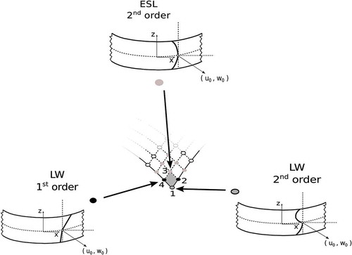
Node 1 Shell Theory = LW with N1 = 2
Node 2 Shell Theory = LW with N2 = 1
Node 3 Shell Theory = HOT with N3 = 2
Node 4 Shell Theory = LW with N4 = 1
According to Equation (15), it is easy to verify that the displacements at a generic point belonging to the shell element can be expressed as given in Equation (16). In this equation, only the displacement component along z-axis is given for simplicity reasons:
It is intended that, due to node-variable expansion theory order, the assembling procedure of each finite element increases in complexity with respect to classical mono-theory finite elements. In the present FE approach, in fact, it is clear that both rectangular and square arrays are handled and opportunely assembled for obtaining the final elemental matrices.
4.1. Fundamental nucleus of the stiffness matrix
Given Unified Formulation and FE approximation, the governing equations for the static response analysis of the multi-layer shell structure can be obtained by using the principle of virtual displacements, which states:
where the term on the left-hand side represents the virtual variation of the strain energy; and A are the integration domains in the plane and the thickness direction, respectively; ∈ and σ are the vector of the strain and stress components; and
is the virtual variation of the external loadings. By substituting the constitutive equations for composite elastic materials Equation (6), the linear geometrical relations Equation (7) as well as Equation (15) into Equation (17), the linear algebraic system in the form of governing equations is obtained in the following matrix expression:
where and
are the element stiffness and load FE arrays written in the form of fundamental nuclei. The mechanical part
is a
matrix, the coupling matrices
,
have dimension
and
respectively, and the electrical part
is a
matrix. The mechanical stiffness nucleus
, and the mechanical external load vector nucleus
are the same defined for the pure mechanical problems, reader can refer to the work [Citation57]. The explicit expression of the stiffness electro-mechanical coupling matrices and the pure electric nucleus with classical FEM method are given in Appendix. In the development of ESL and LW theories, the fundamental nucleus of the stiffness matrix is evaluated at the layer level and then assembled at global structure level, for more details the readers can refer to [Citation41,Citation43]. It must be added that, in this work, an MITC technique is used to overcome the shear locking phenomenon, see [Citation49]. However, for more details about the explicit formulation of the Unified Formulation fundamental nuclei, interested readers are referred to the recent book by Carrera et al. [Citation55].
5 Numerical results
Some problems have been considered to assess the capabilities of the proposed variable-kinematics shell elements and related global/local analysis. These analysis cases comprise both composite and sandwich laminated shell structures with different boundary conditions and loadings. Whenever possible, the proposed multi-theory models are compared to single-theory refined elements. According to Unified Formulation terminology, the latter models are referred to as LWN, where LW stands for Layer-Wise models (LW), and N is the theory approximation order. Eventually, 3D FEM solutions are given, the opportune notation is mentioned case by case. On the contrary, for the sake of clarity, multi-model theories are opportunely described for each numerical case considered.
5.1. Cantilevered cylindrical shell with piezoelectric skins
A cantilever cylindrical shell is analysed to assess the new finite element, as it is shown in , the cylindrical shell is made of an Aluminum core and PZT-5H piezoelectric external skins. The geometrical dimensions are: a = b = 300mm, htotal = 3mm, . The core is made of Aluminum with the following mechanical properties: E = 70.3GPa, v = 0.345,
; the aluminum layer is thick hal = 2,5mm. The upper and lower skins are made of PZT-5H piezoelectric material, and each skin is thick hskin = 0,25mm, the PZT-5H material has the following properties: C11 = C22 = C33 = 126GPa, C12 = 79.5GPa, C13 = C23 = 84.1GPa,
,
,
,
,
,
. The structure is loaded at the external surfaces of the upper and lower skins with a constant uniform electric potential equal to
, and the internal skin surfaces are grounded,
. The shell is cantilevered and the following boundary conditions are applied:
Figure 3. Reference system of the cantilevered cylindrical shell with piezoelectric skins, and three-dimensional representation of the deformation under the electric load.
The structure analyzed in this numerical section is similar to those analyzed in the works of Kioua & Mirza [Citation58], and Kpeky et al. [Citation59]. The present single- and multi-model solutions are compared with a calculated three-dimensional FEM ABAQUS solution. A non-uniform mesh grid of elements ensures the convergence of the solution with a LW4 single-model, see . For the sake of brevity the study of the convergence is here omitted. The adopted refined mesh is necessary to study the behavior of the mechanical and electrical variables along the whole shell domain, and not in one single point. The difficult task is to obtain a good behaviour of the shear stress close to the free edges, avoiding strange oscillations due to the changing of the element size and the free-edge effects.
Figure 4. Non-uniform adopted mesh and graphical representation of the multi-model cases, for the cantilevered cylindrical shell.
Various node-variable kinematic models have been used to perform the global/local analysis of the proposed cylindrical shell structure. The mid-plane domain of the shell structure was subdivided into different higher- and lower-order zones along the axes and
and they are depicted in . Some results of the transverse mechanical displacement
, in-plane stress
, transverse shear stress
, transverse normal stress
, and tranvserse electric displacement
evaluated along the shell thickness are given in tabular form, see . Mono-theory models are compared with those from the present multi-model approach, furthermore the FEM
solution provided by 3D Abaqus C3D20RE element is given.
Table 1. Cantilevered cylindrical shell with piezoelectric skins. Transverse displacement , in-plane stress
, transverse shear stress
, transverse normal stress
, and transverse electric displacement
by various single- and multi-theory models.
Some results in terms of transverse displacement w, and electric potential along the thickness are represented in ,). Some more comments can be made:
Figure 5. Cantilevered cylindrical shell with piezoelectric skins. Transverse displacement and transverse shear stress
for single and multi-model.
The through-the-thickness distribution of the transverse displacement w at the free tip, as shown in ), is correctly predicted by higher-order single-models LW 2, LW 3 and LW 4. The considered multi-models show a loss in the accuracy solution, due to the global polynomial order approximation. It has to be noticed that the description of the free-edge central zone (Case A) and the central shell zone (Case B), by higher-order expansions, leads to appreciable enhancements of the transverse mechanical displacement accuracy, conversely the enrichment of the polynomial order of the free-edge lateral zones (Case C), close to the evaluation point, does not produce any relevant effects.
The behavior of the transverse shear stress
along the thickness, depicted in ), is well described by LW4 single-model, differently the other single-models show losses in the accuracy solution and the interlaminar continuity condition is not satisfied. The multi-models Case A and Case C permit a good description of the shear stress, due to the local higher-order polynomial approximation around the evaluation point. The multi-model Case B shows a poor shear stress description because the evaluation point is locally described by a linear expasion.
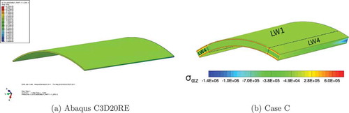
Furthermore the three-dimensional view of the transverse displacement w, on undeformed structure, is given by the finite element 3D Abaqus C3D20RE, see ), and the present mono-model LW 4, see ), and the three-dimensional view of the transverse shear stress by the finite element by the finite element 3D Abaqus C3D20RE, see ), and the present mono-model LW 4, see ).
Figure 6. Cantilevered cylindrical shell with piezoelectric skins, transverse displacement w. Three-dimensional view on undeformed structure by 3D finite element AbaqusC3D20RE, and present single- model LW 4.
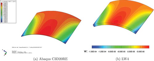
Figure 7. Cantilevered cylindrical shell with piezoelectric skins, transverse shear stress . Three-dimensional view on undeformed structure by 3D finite element AbaqusC3D20RE, and present multi- model Case C.
5.2. Simply-supported composite spherical shell with piezoelectric skins under localized pressure
As second numerical example, a four-layer cross-ply square spherical panel with a cross-ply Gr/Ep composite core and PZT-4 piezoelectric external skins is analyzed, see . The square spherical panel has the following geometrical data:
,
, and
. In respect to the total thickness, a single piezoelectric skin is thick
, while the single core layer is thick
. The material properties of the spherical shell are given in .
Table 2. Material data for multilayered spherical shell.
Figure 8. Reference system of the composite spherical panel with piezoelectric skins. Three-dimensional representation of the deflection of a quarter of the spherical panel under localized pressure.
A localized uniform transverse normal pressure, , is applied to the top surface of the spherical shell on a square region of side length equal to
and centered at the point
, see . The potential at top and bottom position is imposed
. The spherical panel has simply-supported boundary conditions. Due to the simmetry of both the geometry and the load, a quarter of the shell is analyzed and the following symmetry and boundary conditions (simply-supported) are applied:
Figure 9. Mesh zones of the composite spherical panel with piezoelectric skins and graphical representation of the multi-theory models, based on layer-wise models.
The mid-plane domain of the plane structure was subdivided into three zones along the axes and
, as shown in , and multi-theory models Case A, Case B, Case C and Case D are depicted on the FE discretization of a quarter of the spherical panel. A non-uniform mesh grid of 10 × 10 elements, on a quarter of the spherical panel, ensures the convergence of the solution with a LW 4 single-model. For the sake of brevity the study of the convergence is here omitted.
Some results of the transverse mechanical displacement , in-plane stress
, transverse shear stress
, transverse normal stress
, electric potential
, and transvserse electric displacement
evaluated along the spherical shell thickness are given in tabular form, see . Mono-theory models are compared with those from the present multi-model approach, furthermore, a
FEM solution provided by the commercial code
is given. For the transverse shear stresses, the evaluation point is located between the upper piezo-skin and the first composite layer, their results are given for the upper layer with upscript
and for the lower layer with upscript
.
Table 3. Composite four-layered spherical panel with piezoelectric skins. Transverse displacement , in-plane stress
, transverse shear stress
, transverse normal stress
, electric potential
, and transverse electric displacement
by various single- and multi-theory models.
Some results are given in terms of transverse displacement , transverse shear stress
, electric potential
and electric transverse displacement
along the shell thickness. Some more comments can be made:
The primary variables, transverse displacement
Figure 10. Composite four-layered spherical panel with piezoelectric skins. Transverse displacement
For the evaluation of transverse shear stress
Figure 11. Composite four-layered spherical panel with piezoelectric skins. Transverse shear stress
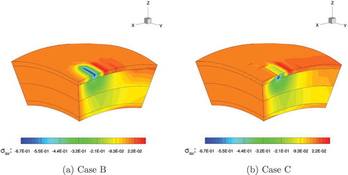
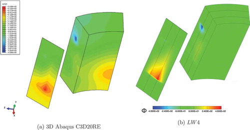
Finally in ,) the three-dimensional distributions of the transverse shear stress , obtained with the Abaqus 3D finite element C3D20RE and the present
single-model respectively, are depicted on a quarter of the spherical shell structure. The present multi-models Case B and Case C are depicted in ,) respectively. It has to be noticed that for the Case B the loaded zone is described by a linear model and the boundary zones by a fourth order kinematics, consequently, the transverse shear stress is not well described in the loaded zone. Differently, the opposite situation is depicted by the multi-model Case C where the loaded zone, described by a fourth order polynomial, is in good agreement with the reference single-model solution LW 4.
Figure 12. Composite four-layered spherical panel with piezoelectric skins. Three-dimensional view of the transverse shear stress , of a quarter of the undeformed structure. 3D Abaqus C3D20RE and mono-model LW 4.
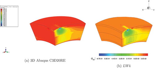
Figure 13. Composite four-layered spherical panel with piezoelectric skins. Three-dimensional view of the transverse shear stress , of a quarter of the undeformed structure. Multi-models Case B and Case C.
5.3. Cantilevered sandwich cylindrical shell with piezoelectric patches
A cantilever sandiwch cylindrical shell is analysed as shown in . The geometrical dimensions are: ,
,
. The upper and lower layers are made of Aluminum with the following mechanical properties:
,
,
. The central layer is made of Foam, with the following properties:
,
,
; a PZT-5H piezoelectric patches is introduced in the foam layer with dimension:
,
,
and it is centered at
, the PZT-5H material has the following properties:
,
,
,
,
,
,
,
,
. The material PZT-5H is polarized in the
-direction, or in
. The three layers have the same thickness
. The structure is loaded at the free tip
with a concentrated transverse mechanical load equal to
. The piezolectric patch is set in open-circuit configuration. The cylindrical shell is cantilevered and the following boundary conditions are applied:
Figure 14. Reference system of the sandwich cylindrical shell with piezoelectric patch under the concentrated mechanical load.
The structure analyzed in this numerical section is derived from the work of Sun and Zhang [Citation60]. The present single- and multi-model solutions are compared with a calculated three-dimensional FEM ABAQUS solution. A non-uniform mesh grid of elements ensures the convergence of the solution with a LW 4 single-model, see . For the sake of brevity, the study of the convergence is here omitted. The adopted refined mesh is necessary to study the behavior of the mechanical and electrical variables along the whole shell domain, and not in one single point. The difficult task is to obtain a good behavior of the mechanical stresses, electric potential, and electric displacements, along with the in-plane directions close to the interfaces of the piezoelectric patch, avoiding strange oscillations due to the changing of the element size.
Figure 15. Non-uniform adopted mesh and graphical representation of the multi-model cases, for the sandwich cylindrical shell.
Various node-variable kinematic models have been used to perform the global/local analysis of the proposed shell structure. The mid-plane domain of the cylindrical panel was subdivided into different higher- and lower-order zones along the axes and
and they are depicted in . Some results of the transverse mechanical displacement
, in-plane stress
, transverse shear stress
, transverse normal stress
, electric potential
, and transverse electric displacement
evaluated along the shell thickness are given in tabular form, see . Mono-theory models are compared with those from the present multi-model approach, furthermore the FEM 3D solution provided by 3D Abaqus C3D20RE element is given.
Table 4. Single-theory and multi-theory models of the sandwich cantilever cylindrical shell under concentrated mechanical load. Transverse displacement , electric potential
, in-plane principal stress
, transverse shear stress
, transverse normal stress
, transverse electric displacement
.
Some results are given in terms of transverse displacement , transverse shear stress
, electric potential
and electric transverse displacement
along the shell thickness. Some more comments can be made:
For the transverse displacement
Figure 16. Sandwich cantilever cylindrical shell under concentrated mechanical load. Transverse displacement
The transverse shear stress
Regarding the electric potential
Figure 17. Sandwich cantilever cylindrical shell under concentrated mechanical load. Electric potential
Regarding the electric transverse displacement
Results in terms of transverse shear stress , electric potential
, in-plane electric displacement
and transverse electric displacement
, along the in-plane
- axis at the interface between the upper skin and the sandwich core, are represented in ,), ,) respectively. For the transverse shear stress and the in-plane electric displacements
, see ,), the
single-model and higher-order multi-models show the same behavior and accuracy. Higher peak values are noticeable at the side-edges of the piezoelectric patch
. The multi-model Case B show an increase of the maximum peak value at
, this is due to the transition zone between LW 4 and LW 1 models, as shown in . The linear single-model LW1 completely underestimate the stress description.
Figure 18. Sandwich cantilever cylindrical shell under concentrated mechanical load. Transverse shear stress , and in-plane electric displacement
along the
direction. Single and Multi-theory models.
Figure 19. Sandwich cantilever cylindrical shell under concentrated mechanical load. Electric potential , and transverse electric displacement
along the
direction. Single and Multi-theory models.
The electric potential is well depicted by all the single and multi-models, as shown in ), as to be noticed that the linear single-model LW 1 has little losses in accuracy in center part of the patch. As mentioned before, the multi-model Case B show an increase of the maximum peak value at , this is due to the transition zone between LW 4 and LW 1 models.
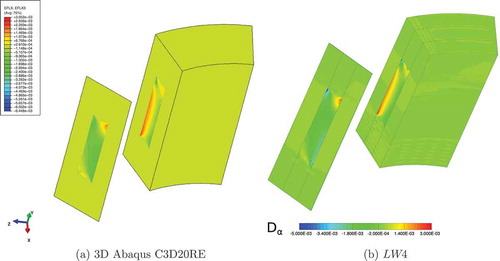
Regarding the transverse electric displacement , the single LW4 and all the multi-models, as shown in ), show a good description along with the in-plane direction with some small oscillations in the zones close to the side-edge of the patch at
. It has to be noticed that the linear single-model LW1 is completely not able to correctly describe the transverse electric displacement, at
the peak values show an inverse, positive, sign with respect to the other single and multi-models, and at
the maximum peak value is almost double with respect to the other models.
Finally in ,) the three-dimensional distributions of the electric potential , obtained with the Abaqus 3D finite element C3D20RE and the present
single-model, respectively are depicted on the entire cylindrical shell structure, represented with an initial radial section at
and the middle radial section at
. It has to be noticed that the present LW 4 single model well describes the phenomena without imposing any boundary condition, the electric potential tend naturally to zero.
Figure 20. Sandwich cantilever cylindrical shell under concentrated mechanical load. Three-dimensional view of the electric potential , on undeformed structure. 3D Abaqus C3D20RE and mono-model LW 4.
The electric in-plane displacements is depicted in ,), respectively. The present LW 4 single model and the Abaqus 3D finite element C3D20RE are in good agreement on the whole shell structure.
Figure 21. Sandwich cantilever cylindrical shell under concentrated mechanical load. Three-dimensional view of the in-plane electric displacement , on undeformed structure. 3D Abaqus C3D20RE and mono-model LW 4.
6 Conclusions
In this paper a new methodology for global/local analysis of composite and sandwich shell structure embedding piezoelectric skins and patches has been introduced. This approach makes use of advanced finite shell elements with node-dependent kinematics, which are formulated in the domain of the Unified Formulation. In fact, the finite element arrays of the generic shell element are formulated in terms of fundamental nuclei, which are invariants of the theory approximation order and the modelling technique (ESL, LW). In this manner, the shell theory can vary within the same finite elements with no difficulties. The resulting global/local approach is very efficient because it does not employ any mathematical artifice to enforce the displacement/stress continuity, such as those methods based on Lagrange multipliers or overlapping regions. The present node-dependent variable kinematic model allows to locally improve the solution. Two main aspects can be highlighted:
A reduction of computational costs with respect to Layer-Wise single-model solutions, and a simultaneous multi-models global-local analysis can be performed in one-single analysis step.
An accurate representation of secondary variables (mechanical stresses and electric displacements) in localized zones is possible with DOFs reduction if an accurate distribution of the higher-order kinematic capabilities is performed. On the contrary, the accuracy of the solution in terms of primary variables (mechanical displacements and electric potential) values depends on the global approximation over the whole structure.
The efficacy of the node-dependent variable kinematic and global/local models, thus, depends on the characteristics of the problem under consideration as well as on the required analysis type. The proposed methodology has been widely assessed in this paper by analysing composite and sandwich shells embedding piezoelectric skins and patches, in sensor and actuator configurations, and different piezoelectric material polarizations, and by comparison with solutions from finite element commercial tools.
In this paper, the novel approach for the global/local models has been only assessed for static coupled electro-mechanical analysis. A possible future extension will deal with thermo-mechanical problems. These promising beginnings, concerning the static analysis results, induce to shift the investigation of the node-dependent kinematic efficiency and accuracy on dynamic (free-vibration, frequency response, etc. etc.) and/or on transient problems (wave propagation, impact).
Acknowledgment
E. Carrera and G.M. Kulikov have been supported by the Russian Science Foundation (Grant No. 15-19-30002).
Disclosure statement
No potential conflict of interest was reported by the authors.
Additional information
Funding
References
- R.D. Mindlin, Forced thickness-shear and flexural vibrations of piezoelectric crystal plates, J. Appl. Phys 23 (1952), pp. 83–91. doi:10.1063/1.1701983
- E.P. EerNisse, Variational method for electroelastic vibration analysis, IEEE Trans. Sonics Ultrasonics 14 (4) (1967), pp. 153–213. doi:10.1109/T-SU.1967.29431
- H.F. Tiersten and R.D. Mindlin, Forced vibrations of piezoelectric crystal plates, Q. Appl. Math. 20 (2) (1962), pp. 107–126. doi:10.1090/qam/99964
- H.F. Tiersten, Linear piezoelectric plate vibrations, New York Plenum Press, New York, 1969.
- D.A. Saravanos and P.R. Heyliger, Mechanics and computational models for laminated piezoelectric beams, plates and shells, Appl. Mechanics Rev. 52 (10) (1999), pp. 305–324. doi:10.1115/1.3098918
- S. Kapuria, A coupled zig-zag third-order theory for piezoelectric hybrid cross-ply plates, J. Appl. Mechanics 71 (2004), pp. 604–618. doi:10.1115/1.1767170
- C. Ossadzow-David and M. Touratier, A multilayered piezoelectric shell theory, Compos. Sci. Technol 64 (2004), pp. 2121–2158. doi:10.1016/j.compscitech.2004.03.005
- P. Heyliger, K.C. Pei, and D.A. Saravanos, Layerwise mechanics and finite element model for laminated piezoelectric shells, AIAA J. 34 (11) (1996), pp. 2353–2413. doi:10.2514/3.13401
- D. Ballhause, M. D’Ottavio, B. Kroplin, and E. Carrera, A unified formulation to assess multilayered theories for piezoelectric plates, Comput. Struct 83 (15–16) (2005), pp. 1217–1235. doi:10.1016/j.compstruc.2004.09.015
- M. D’Ottavio, D. Ballhause, B. Kroplin, and E. Carrera, Closed-form solutions for the free-vibration problem of multilayered piezoelectric shells, Comput. Struct 84 (2006), pp. 1506–1524. doi:10.1016/j.compstruc.2006.01.030
- A. Benjeddou, J. Deu, and S. Letombe, Free vibrations of simply-supported piezoelectric adaptive plates: An exact sandwich formulation, Thin-Walled Struct 40 (2002), pp. 573–666. doi:10.1016/S0263-8231(02)00013-7
- G.M. Kulikov and S.V. Plotnikova, Exact geometry piezoelectric solid-shell element based on the 7-parameter model, Mech. Adv. Mate. Struct 18 (2011), pp. 133–146. doi:10.1080/15376494.2010.496067
- G.M. Kulikov and S.V. Plotnikova, A new approach to three-dimensional exact solutions for functionally graded piezoelectric laminated plates, Compo. Struct. 106 (2013), pp. 33–46. doi:10.1016/j.compstruct.2013.05.037
- G. Rama, A 3-node piezoelectric shell element for linear and geometrically nonlinear dynamic analysis of smart structures, FACTA UNIVERSITATIS, Series: Mech. Eng 15 (1) (2017), pp. 31–44. doi:10.22190/FUME170225002R
- D. Marinković and G. Rama, Co-rotational shell element for numerical analysis of laminated piezoelectric composite structures, Composites Part. B: Eng 125 (2017), pp. 144–156. doi:10.1016/j.compositesb.2017.05.061
- T. Nestorović, S. Shabadi, D. Marinković, and M. Trajkov, Modeling of piezoelectric smart structures by implementation of a user defined shell finite element, FACTA UNIVERSITATIS, Series: Mech. Eng 11 (1) (2013), pp. 1–12.
- D. Marinković, H. Köppe, and U. Gabbert, Degenerated shell element for geometrically nonlinear analysis of thin-walled piezoelectric active structures, Smart Mater. Struct. 17 (1) (2008), pp. 015030. doi:10.1088/0964-1726/17/01/015030
- S. Gohari, S. Sharifi, and Z. Vrcelj, A novel explicit solution for twisting control of smart laminated cantilever composite plates and beams using inclined piezoelectric actuators, Compo. Struct. 161 (2017), pp. 477–504. doi:10.1016/j.compstruct.2016.11.063
- C.S. Rekatsinas and D.A. Saravanos, A cubic spline layerwise time domain spectral FE for guided waves simulation in laminated composite plate structures with physically modeled active piezoelectric sensors, Int. J. Solids. Struct 24 (1) (2017), pp. 176-191.
- Babushka, I., Chandra, J., & Flaherty, J. E. (Eds.). Adaptive Computational Methods for PartialDifferential Equations Vol. 16. Siam, Proceedings, College Park, PA, (1983).
- B.A. Szabo and I. Babuska, Finite Element Analysis, John Wiley & Sons, 1991.
- K.J. Bathe, Finite element procedure, Prentice Hall, 1996.
- D.M. Thompson and O.H. Jr Griffin, 2-D to 3-D global/local finite element analysis of cross-ply composite laminates, J. Reinforced Plas. Compos. 9 (1990), pp. 492–502. doi:10.1177/073168449000900506
- K.M. Mao and C.T. Sun, A refined global-local finite element analysis method, Int. J. Numer. Methods Eng 32 (1991), pp. 29–43. doi:10.1002/(ISSN)1097-0207
- J.D. Whitcomb and K. Woo, Application of iterative global/local finite element analysis. part 1: Linear analysis, Commun. Numer. Methods Eng 9 (9) (1993), pp. 745–756. doi:10.1002/cnm.1640090905
- J.D. Whitcomb and K. Woo, Application of iterative global/local finite element analysis. Part 2: Geometrically non-linear analysis, Commun. Numer. Methods Eng 9 (9) (1993), pp. 757–766. doi:10.1002/cnm.1640090906
- A. Pagani, S. Valvano, and E. Carrera, Analysis of laminated composites and sandwich structures by variable-kinematic MITC9 plate elements, J. Sandwich. Structures. Mater (2016). doi:10.1177/1099636216650988
- E. Carrera, A. Pagani, and S. Valvano, Shell elements with through-the-thickness variable kinematics for the analysis of laminated composite and sandwich structures, Composites Part B 111 (2017), pp. 294–314. doi:10.1016/j.compositesb.2016.12.001
- E. Carrera and S. Valvano, A variable kinematic shell formulation applied to thermal stress of laminated structures, J. Thermal Stresses 40 (2017), pp. 803–827. doi:10.1080/01495739.2016.1253439
- E. Carrera and S. Valvano, Analysis of laminated composite structures with embedded piezoelectric sheets by variable kinematic shell elements, J. Intell. Mater. Syst. Struct 28 (20) (2017), pp. 2959–2987. doi:10.1177/1045389X17704913
- F. Brezzi and L.D. Marini, The three-field formulation for elasticity problems, GAMM Mitteilungen 28 (2005), pp. 124–153. doi:10.1002/gamm.v28.2
- E. Carrera, A. Pagani, and M. Petrolo, Use of Lagrange multipliers to combine 1D variable kinematic finite elements, Comput. Struct. 129 (2013), pp. 194–206. doi:10.1016/j.compstruc.2013.07.005
- H. Ben Dhia, Multiscale mechanical problems: The Arlequin method, Comptes Rendus De L Academie Des Sciences Series IIB Mechanics Physics Astronomy 326 (12) (1998), pp. 899–904.
- H. Ben Dhia, The Arlequin method as a flexible engineering tool, Int. J. Numer. Methods Eng 62 (11) (2005), pp. 1442–1462. doi:10.1002/nme.1229
- H. Ben Dhia, Further insights by theoretical investigations of the multiscale Arlequin method, Int. J. Multiscale Computational Eng. 6 (3) (2008), pp. 215–232. doi:10.1615/IntJMultCompEng.v6.i3
- H. Hu, S. Belouettar, M. Potier-Ferry, and E.M. Daya, Multi-scale modelling of sandwich structures using the Arlequin method. Part I: Linear modelling, Finite Elem. Anal. Des. 45 (1) (2008), pp. 37–51. doi:10.1016/j.finel.2008.07.003
- H. Hu, S. Belouettar, M. Potier-Ferry, E.M. Daya, and A. Makradi, Multi-scale nonlinear modelling of sandwich structures using the Arlequin method, Finite Elem. Anal. Des. 92 (2) (2010), pp. 515–522.
- F. Biscani, G. Giunta, S. Belouettar, E. Carrera, and H. Hu, Variable kinematic beam elements coupled via Arlequin method, Compo. Struct. 93 (2) (2011), pp. 697–708. doi:10.1016/j.compstruct.2010.08.009
- F. Biscani, G. Giunta, S. Belouettar, E. Carrera, and H. Hu, Variable kinematic plate elements coupled via Arlequin method, Int. J. Numer. Methods Eng 91 (2012), pp. 1264–1290. doi:10.1002/nme.v91.12
- F. Biscani, P. Nali, S. Belouettar, and E. Carrera, Coupling of hierarchical piezoelectric plate finite elements via Arlequin method, J. Intell. Mater. Syst. Struct 23 (7) (2012), pp. 749–764. doi:10.1177/1045389X12437885
- E. Carrera, S. Valvano, and G.M. Kulikov, Multilayered plate elements with node-dependent kinematics for electro-mechanical problems, Int. J. Smart Nano Mater. (In Press). doi:10.1080/19475411.2017.1376722
- E. Carrera, A. Pagani, and S. Valvano, Multilayered plate elements accounting for refined theories and node-dependent kinematics, Composites Part. B: Eng 114 (2017), pp. 189–210. doi:10.1016/j.compositesb.2017.01.022
- S. Valvano and E. Carrera, Multilayered plate elements with node-dependent kinematics for the analysis of composite and sandwich structures, FACTA UNIVERSITATIS, Series: Mech. Eng 15 (1) (2017), pp. 1–30. doi:10.22190/FUME170315001V
- K.J. Bathe and E. Dvorkin, A formulation of general shell elements - the use of mixed interpolation of tensorial components, Int. J. Numer. Methods Eng 22 (1986), pp. 697–722. doi:10.1002/nme.1620220312
- K.J. Bathe and F. Brezzi, A simplified analysis of two plate bending elements-the MITC4 and MITC9 elements, Proceedings, Numerical Methods in Engineering: Theory and Applications, 1987.
- K.J. Bathe, F. Brezzi, and S.W. Cho, The MICT7 and MITC9 plate bending elements, Comput. Struct 32 (3–4) (1989), pp. 797–814. doi:10.1016/0045-7949(89)90365-9
- M.L. Bucalem and E. Dvorkin, Higher-order MITC general shell elements, Int. J. Numer. Methods Eng 36 (1993), pp. 3729–3754. doi:10.1002/nme.1620362109
- M. Cinefra, S. Valvano, and E. Carrera, Thermal stress analysis of laminated structures by a variable kinematic MITC9 shell element, J. Thermal Stresses 39 (2) (2016), pp. 121–141. doi:10.1080/01495739.2015.1123591
- M. Cinefra, S. Valvano, and E. Carrera, A layer-wise MITC9 finite element for the free-vibration analysis of plates with piezo-patches, Int. J. Smart Nano Mater. 6 (2) (2015), pp. 85–104. doi:10.1080/19475411.2015.1037377
- E. Carrera, Theories and finite elements for multilayered plates and shells: A unified compact formulation with numerical assessment and benchmarking, Arch. Computational Methods Eng. 10 (3) (2003), pp. 215–296. doi:10.1007/BF02736224
- E. Carrera, Multilayered shell theories accounting for layerwise mixed description, Part 1: Governing equations, AIAA J. 37 (9) (1999), pp. 1107–1116. doi:10.2514/2.821
- E. Carrera, Multilayered shell theories accounting for layerwise mixed description, Part 2: Numerical evaluations, AIAA J. 37 (9) (1999), pp. 1117–1124. doi:10.2514/2.822
- J.N. Reddy, An evaluation of equivalent-single-layer and layerwise theories of composite laminates, Compo. Struct. 25 (1993), pp. 21–35. doi:10.1016/0263-8223(93)90147-I
- E. Carrera, S. Brischetto, and P. Nali, Plates and Shells for Smart Structures: Classical and Advanced Theories for Modeling and Analysis, John Wiley & Sons, 2011.
- E. Carrera, M. Cinefra, M. Petrolo, and E. Zappino, Finite Element Analysis of Structures through Unified Formulation, John Wiley & Sons, 2014.
- N.N. Rogacheva, The Theory of Piezoelectric Shells and Plates, CRC Press, Boca Raton, 1994.
- E. Carrera, S. Valvano, and G.M. Kulikov, Global-Local Analysis of Composite and Sandwich Multilayered Structures by Shell Elements with Node-Dependent Kinematics. To be submitted.
- H. Kioua and S. Mirza, Piezoelectric induced bending and twisting of laminated composite shallow shells, Smart Mater. Struct. 9 (2000), pp. 476–484. doi:10.1088/0964-1726/9/4/310
- F. Kpeky, F. Abed-Meraim, H. Boudaoud, and E.M. Daya, Linear and quadratic solidshell finite elements SHB8PSE and SHB20E for the modeling of piezoelectric sandwich structures, Mech. Adv. Mate. Struct (2017), pp. 1–20. doi:10.1080/15376494.2017.1285466.
- C.T. Sun and X.D. Zhang, Use of thickness-shear mode in adaptive sandwich structures, Smart Mater. Struct. 4 (1995), pp. 202–206. doi:10.1088/0964-1726/4/3/007
Appendix
The pure electrical stiffness nucleus is defined as follows:
The stiffness electro-mechanical coupling matrices and
are defined as follows:
Actuation in 3–1 mode
Actuation in 1–5 mode
where comma denote partial derivatives with respect to the spatial directions. The fundamental nucleus as given above is the basic building block for the construction of the element stiffness matrix of classical, refined and variable-kinematic theories. In fact, given these nine components, element stiffness matrices of arbitrary shell models can be obtained in an automatic manner by expanding the fundamental nucleus versus the indexes ,
,
, and
.