
 ?Mathematical formulae have been encoded as MathML and are displayed in this HTML version using MathJax in order to improve their display. Uncheck the box to turn MathJax off. This feature requires Javascript. Click on a formula to zoom.
ABSTRACT
An algorithm for the layout of a piezoelectric that provides the most efficient performance within a specified range of vibration frequencies is proposed in this paper. This algorithm is based on the consideration of a special parameter within the area of a piezoelectric element’s possible location. This parameter characterizes the superposition of electromechanical coupling coefficients’ for all the natural vibration frequencies included in a specified frequency range. The condition for defining the best option for location of the piezoelectric element in the case of several equivalent positions is specified. The efficiency of the proposed algorithm is shown numerically. The electromechanical coupling coefficients were calculated numerically based on solution to the problem of natural vibrations for electroelastic bodies using a finite element method. The calculations were performed to define the best location for a single piezoelectric element at the surface of a thin-walled shell having a half-cylindrical shape. The results are presented for natural vibration frequencies within the frequency range from 0 up to 1100 Hz. The numerical results were obtained by solving the problem of natural vibrations with a finite element method using the ANSYS software package.
Graphical Abstract
1. Introduction
There is a necessity to search for new solutions to control the dynamic behaviour of a structure, including problems of excitation, registration or damping of vibrations and structural shape control, when designing modern high-tech structures One such solution involves supplementing the original structure with elements made of piezoelectric materials as these kinds of elements can be connected to an external electric circuit that can provide additional vibration control [Citation1].
The efficiency of a piezoelectric element when using such a control strategy depends on many factors, such as the existing parameters of the original structure (geometry, operational conditions), the material properties of the piezoelectric element, its geometry and its layout on the structure. The efficient operation of a piezoelectric element under the specified conditions can be achieved by varying the parameters mentioned above.
However, problems can emerge when using such a structural control strategy, whereby the electric circuit setup using the parameters provided to achieve a required dynamic behavior at a specific frequency becomes inefficient when the frequency of the external excitation changes. Regarding this, it is important to guarantee the effective performance of a dynamic behaviour control strategy aided by minimal technical devices (such as a single piezoelectric element with a simple shunting circuit) within any specified frequency range, including several natural vibration frequencies of the structure, such as understudy herein, especially when rigorous restrictions are put on the mass and dimensions of a structure.
The present approaches for passive multimodal vibration control are based on the use of piezoelectric elements and passive external electric circuits and can generally be divided into two basic groups:
employment of a single piezoelectric element and a complicated branched shunting circuit that enables damping several vibration modes [Citation2–Citation10];
employment of several piezoelectric elements [Citation11–Citation20].
For the latter group, it is also possible that all the piezoelectric elements could be combined into a common network connected to a single shunting circuit [Citation13–Citation18]. Otherwise though, piezoelectric elements are generally not connected to each other and instead each one has its own shunting circuit [Citation16,Citation17]. In this regard, a number of researchers consider an array of piezoelectric elements uniformly distributed across a surface of a structure having the shape of a beam in order to realize multimodal control strategy [Citation18–Citation20].
Each of these approaches has its own advantages and drawbacks. The drawbacks include the following:
the complexity of tuning a branched shunting circuit;
the bulkiness of a branched circuit, that can affect the stability of the system performance;
a necessity to consider a number of restrictions imposed by the weight and dimensions of a structure on the dimensions and number of piezoelectric elements used.
It was shown in [Citation21] that a large number of engineering applications require a reduction in the number of sensors and actuators used for structural dynamic behavior control. This problem leads to the need to exploit these elements in a multimodal regime. Thus, the problem of controlling the dynamic behavior of structures by using the simplest configurations of shunting circuits and a minimal set of additional elements (i.e. piezoelectric elements) is rather acute.
The effective performance of a piezoelectric element depends on its location on the structure. Thus, it is important to locate the piezoelectric element in such a way that enables its efficient operation within the frequency range under consideration at several resonant frequencies and corresponding mode shapes.
The determination of the optimal location for a piezoelectric element for single-mode vibration damping was first considered in [Citation22]. It was shown that the optimal locations for a piezoelectric element’s layout are areas where the mean strains have the highest values. Conventionally, passive vibration dampers are located at such positions where the structural strain energy, defined on the basis of an analysis of the strains’ distribution, is maximal [Citation23,Citation24]. Alongside this, it should be considered that the addition of even one piezoelectric element changes the picture of the deformations and the spectrum of natural vibration frequencies of a structure.
A number of review papers have been published [Citation23,Citation25–Citation27], highlighting about 260 papers devoted to the problem of determining the optimal layout of piezoelectric elements in a structure, with the general impression being that despite the manifold number of methods and approaches for solving this problem, the layout of a piezoelectric element is still rather an art and is mostly based on the intuition of the researcher. Herewith, it was pointed also out in papers [Citation23] and [Citation27] that the improper layout of a piezoelectric element in a structure may lead to violation of its stable operation, ultimately leading to a failure in its performance. Due to this problem, the review paper [Citation26] systematically presented criteria for the optimal layout of piezoelectric elements from the considered papers in order to minimize the intuitive element when making decisions on the layout. The aspects considered in [Citation25] mainly related to the smart-systems with active feedback, such as active dynamic behavior control systems and energy harvesting systems. The problem of optimization of the layout of piezoelectric elements for passive systems in many cases is reduced to the search for such a location to place the piezoelectric element where it would show the highest electromechanical coupling coefficient value. In [Citation25], special attention is paid to the problem of determining the optimal layout for piezoelectric elements that act as sensors or actuators on structures having a different geometry (beams, plates, spatial structures) with the aim to achieve vibration damping or structural dynamic behavior control depending on the external impact.
All the numerous approaches for defining the location of piezoelectric elements that act as sensors or actuators can actually be divided into two groups: derivation of the criterion that would allow estimating the quality of the piezoelectric element location (in fact this is the goal function of the optimization problem) or development of optimization methods that would allow finding the minimum or maximum of the criterion. The required results, which depend on the goal of the piezoelectric element usage, should match this criterion. The amount of harvested electric energy, the level of electric potential generated on the electrodes, the controllability of a structure, the damping of vibration at the specified frequency, etc. [Citation23,Citation25,Citation27–Citation37] can all play a role in the goals set.
Optimal places for the layout of piezoelectric sensors or actuators depend on the chosen optimization criterion and the purpose for the application of the piezoelectric elements [Citation26]. Different authors propose various conditions for determination of the optimal location of a piezoelectric element for passive systems (such as the strain energy [Citation23,Citation38], level of electric charge [Citation23], level of electric potential [Citation38], etc.). The most commonly used condition for seeking the optimal piezoelectric element location is based on the maximal value of the electromechanical coupling coefficient [Citation23,Citation27,Citation28]. This coefficient characterizes the degree of transformation of mechanical energy into electric energy and vice versa.
Different algorithms for defining the optimal location of piezoelectric elements have been proposed in order to realize the above-mentioned approaches to vibration control. The optimal placement of sensors/actuators has been achieved using various objective functions, like maximizing the degree of controllability, minimizing the control effort, minimizing the spillover effects, maximizing the modal forces applied by piezoelectric actuators and by optimizing techniques, such as genetic algorithm (GA), simulated annealing (SA), sequential best adding (SBA) algorithm, penalty function method, swarm intelligence algorithm, and the tabu search method, etc. [Citation26]. In papers [Citation29–Citation31], a genetic algorithm was applied for searching for options for the optimal location of piezoelectric elements. Singular value analysis (SVD) approaches have also been used as an objective function to find the optimal locations of the actuators by a number of authors [Citation39,Citation40].
As noted in the conclusions to the review paper [Citation26], where over 100 papers were considered, most investigations tend to be oriented on simple structures having the form of beams and plates. Herewith, investigations related to the layout of piezoelectric sensors or actuators for real structures having a complex shape are almost absent.
The possibility of multimodal vibration damping using a single piezoelectric element and single resonant RL-circuit was numerically shown in [Citation41]. This approach has obvious advantages over conventional ones due to the fact that mass change is minimal since only one piezoelectric element is used. Moreover, the process of the shunting circuit tuning is reduced to a search only for two parameters: resistance and inductance. However, in this case, the layout of the piezoelectric element plays the special role.
Unfortunately, among the large number of approaches related to determining the optimal location of piezoelectric elements, no approaches have been found for defining the optimal location of a single piezoelectric element providing its efficient performance within some specified frequency range when it is attached to a structure with an arbitrary configuration. This fact led to the necessity to develop the special algorithm considered in the present paper to allow finding the solution to the problem of achieving an efficient performance of a single piezoelectric element within a specified frequency range.
In the present study, the reliability and efficiency of the proposed algorithm were demonstrated numerically on the example of a shell structure having a half-a-cylinder shape. The numerical results were obtained by solving problems of natural vibrations and of steady-state vibrations using the finite element method realized in the ANSYS software package (license: Academic Research Mechanical and CFD No 1,064,623).
2. Algorithm for determining the optimal location of a piezoelectric element providing the best performance
The electromechanical coupling coefficient proposed in [Citation1] was utilized as an effective parameter that could be used to estimate the efficiency of the given piezoelectric element for damping vibrations at a single frequency:
where ,
are the natural vibration frequencies of the structure with the piezoelectric element operating in the open circuit (o/c) and short circuit (s/c) modes. The open circuit mode is realized in the case when one of the electrodes of the piezoelectric element is grounded (electric potential value is equal to zero) and the other one is free of load. In the short circuit conditions, both electrodes are grounded, i.e. the value of electric potential is set equal to zero.
The best option for the piezoelectric element’s location for the corresponding vibration mode (where
is the number of natural vibration frequencies of a structure included in the specified frequency range) is defined by the point on the surface (or its part) of the structure S. This point is characterized by the coordinates (
) that define the location of the piezoelectric element’s center of masses. At this point the maximal value of the electromechanical coupling coefficient
is reached [Citation41]:
It should be taken into account that the best piezoelectric element’s location may be different for different structural mode shapes included in the frequency range under consideration. It was pointed out in the work [Citation42] with the example of a flexural plate that the optimal options for the location of a piezoelectric element are different for different vibration modes as well as for different rates of damping of vibrations.
Thus, some kind of superposition of patterns of the distribution of electromechanical coupling coefficients obtained separately for each of the n structural vibration frequencies under study should be considered when defining the optimal location of a piezoelectric element that implies its efficient application within the specified frequency range. However, consideration of the simple sum of
as such a superposition is incorrect.
First, an area with maximal values of the coupling coefficient for one vibration mode can be an area with minimal values of the coupling coefficient for another vibration mode. Thus, a situation may emerge where areas of the maximal values of the sum pattern of distribution
will not correspond to the optimal position of the piezoelectric element, neither for two frequencies simultaneously, nor for any of two frequencies separately.
Second, the maximal values of may sufficiently differ in magnitude for different frequencies. Herewith in comparison with the highest value magnitude
, the contribution of the remaining coefficients
obtained for j-th frequencies in a value of
that can be negligible. In this case, the piezoelectric element located according to the maximal value of
would show an efficient performance only for the frequency having the highest value of
. Regarding this, the parameter
, calculated according to the formula (3), was introduced.
Here, and
are the initial and end numbers of the frequencies (according to the global numbering of eigenfrequencies) in the specified frequency range and
are the electromechanical coupling coefficient for each possible location of the mass center of piezoelectric element at vibration modes under consideration.
This parameter does not have the meaning of an electromechanical coupling coefficient and is a relative index whose magnitude qualitatively defines a piezoelectric element’s location, where its most efficient application for structural vibration modes within the frequency range under consideration is achieved.
The best location for a piezoelectric element’s center of mass, where the parameter has the highest value, is defined on the basis of an analysis of the pattern of distribution of the
parameter values across the surface of a structure S. This condition can be written in the form of:
For the defined in such a way optimal location of a piezoelectric element, it will show the best performance at all natural vibration frequencies included in the frequency range under study. However, the possible locations of the piezoelectric element having the highest value of
may not be unique.
The number of such possible locations of the piezoelectric element where are very close to each other in magnitude depends on a number of factors: the choice of frequency range one is interested in, the symmetry of the structure, etc. However, these possible location options can be nonequivalent between each other when one considers the values of the electric potential generated by the piezoelectric element at each mode included in the specified frequency range.
Let us suppose that the results of the numerical calculations revealed such possible options for the piezoelectric element’s location with very close values of
. In order to choose the most preferable location option, the following algorithm is proposed.
For each j-th () option of piezoelectric element’s location the following quantities should be calculated:
● the values of the electromechanical coupling coefficients for each i-th vibration mode from the frequency range under consideration related to the j-th location option having the maximal value of P;
● the magnitudes of the deviations of the maximal values of the electromechanical coupling coefficients , which correspond to the optimal location of the piezoelectric element for only one single i-th mode, from values of
, i.e.
the sum magnitude of these deviations
for all the vibration modes from the frequency range under consideration.
Next from all of the calculated values of (
), the minimal magnitude value
should be chosen:
The minimal value of the sum deviation corresponds to the best location of the piezoelectric element, with its most efficient application within the range of structural vibration frequencies from
up to
.
3. Numerical example of the proposed algorithm
An application of the proposed algorithm for choosing the location of the piezoelectric element at the surface of the thin-walled shell () is considered. This location should provide the best performance for the piezoelectric element.
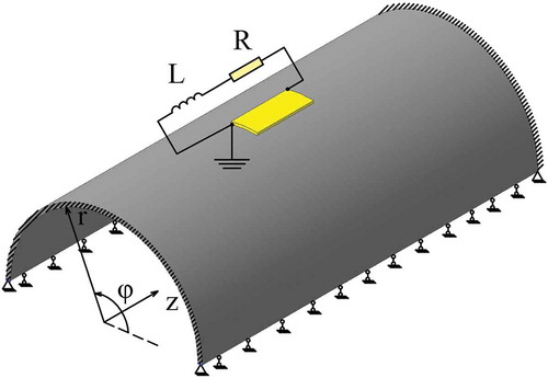
Figure 1. Computation scheme of the shell with the piezoelectric element.
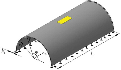
The parameters of the shell geometry are as follows: mm,
mm,
mm. The shell is made of purely elastic material with the following values of material constants:
Pa,
,
kg/m3. As a piezoelectric element, the element in the shape of a sector of the ring with the following geometric parameters was chosen:
mm,
, thickness
mm, length
mm.
The piezoelectric element is made of piezoceramics PZT-4 polarized along the r-axis having the following mechanical characteristics: Pa,
Pa,
Pa,
Pa,
Pa,
Pa,
C/m2,
C/m2,
C/m2,
F/m,
F/m,
kg/m3. The upper and lower piezoelectric element surfaces are covered with electrodes.
Spatial structural 20-nodal finite elements having a quadratic approximation of nodal unknowns (SOLID186 from ANSYS element library [Citation43]) were used for modeling of the shell. Spatial coupled 20-nodal finite elements having a quadratic approximation of nodal unknowns (SOLID226 from ANSYS element library [Citation43]) were used for modeling the piezoelectric element.
The first eight natural vibration frequencies (in Hz) of the shell without the piezoelectric element are correspondingly equal to: 557.4; 587.7; 620.2; 759.6; 803.8; 987.5; 1012.1; 1035.0. The search option for location of the piezoelectric element guaranteeing its best performance for the first three vibration modes is considered.
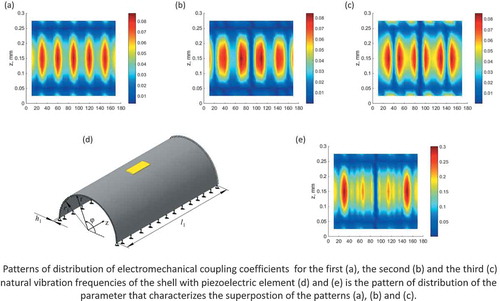
The patterns of distribution of the electromechanical coupling coefficients’ values for the first three vibration modes depending on the location of the piezoelectric element are shown in . The presented results indicate that the maximal values of
for each frequency are reached at different options of the piezoelectric element’s location.
Figure 2. Patterns of distribution of the electromechanical coupling coefficients for the first (a), the second (b) and the third (c) natural vibration frequencies of the shell with the piezoelectric element and pattern of distribution of the parameter (d)
for these frequencies.
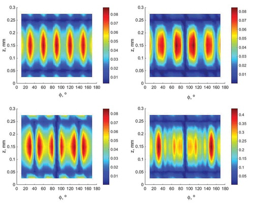
represents the pattern of distribution of values of the new parameter . The symmetry of patterns shown in is due to the symmetry of the structure under study.
According to the proposed algorithm, the optimal options for the best performance of the piezoelectric element in the first three vibration modes are two symmetrical points having the following coordinates of the piezoelectric element’s center of mass: ,
m (point
) and
,
m (point
).
Taking into account the symmetry of the structure, is accepted for the case under study. The value of
and the corresponding quantities required for its calculation according to the formula (5) are presented in in order to characterize the found solution. For comparison, the value of
and all the required quantities for its calculation are also represented in . For
, the piezoelectric element’s location is not optimal and has the following coordinates of its center of mass:
,
m. In this case, the piezoelectric element’s location ensures the best performance for only the first vibration mode.
Table 1. The quantities that define for the frequency range from 500 to 700 Hz.
Further, the results of the search for the location of the piezoelectric element providing the best performance within the frequency ranges from 700 to 900 Hz, from 900 to 1100 Hz and from 0 to 1100 Hz are presented as another illustration of the proposed algorithm.
The analysis of patterns of distribution of values of the parameter for the above-mentioned frequency ranges revealed the following (taking into account the symmetry):
● one option for the piezoelectric element’s location () for the frequency range from 700 to 900 Hz having the following coordinates of its center of masses:
,
m (
point);
● two options for the piezoelectric element’s location () for the frequency range from 900 to 1100 Hz having the following coordinates of its center of masses:
,
m (
point) and
,
m (
point);
● three options for the piezoelectric element’s location () for the frequency range from 0 to 1100 Hz having the following coordinates of its center of masses:
,
m (
point);
,
m (
point);
,
m (
point) when considering all eight natural vibration frequencies under study.
The presented coordinates of the center of mass of the piezoelectric element were defined by the highest values of the parameter . According to the presented algorithm, the point
should be chosen as the best option for the piezoelectric elements' location within the frequency range from 900 to 1100 Hz. The point
should be chosen as the best option for the piezoelectric element’s location within the frequency range from 0 to 1100 Hz. The magnitude of
allows estimating the efficiency of the piezoelectric element within the specified frequency range (–).
Table 2. The quantities that define for the frequency range from 700 to 900 Hz.
Table 3. The quantities that define for the frequency range from 900 to 1100 Hz.
Table 4. The quantities that define for the frequency range from 0 to 1100 Hz.
4. Validation of the obtained results
The implementation of the present algorithm allows providing the best or optimal (within the frameworks of the formulated conditions) realization of the direct or inverse piezoelectric effect for the specified frequency range. This means that it is possible to achieve relatively large deformations within the specified frequency range using the optimally located piezoelectric element as an actuator (inverse piezoelectric effect) for the excitation of vibrations by setting the electric potential on a single piezoelectric element.
Considering the direct piezoelectric effect, the optimally located piezoelectric element can be most-efficiently used within the specified frequency range as a sensor or electric energy power supply when damping the vibrations with the aid of a passive external electrical circuit. This effect will be shown in the following example.
Consider the point A loaded with the periodic force (
) (). represents the frequency response of the amplitude values of voltage generated across the piezoelectric element’s electrodes for two options for the piezoelectric element’s layout.
Figure 3. Frequency response for the electric potential generated at the top electrode of the piezoelectric element (b) when exciting vibrations by variable external force applied to the point A (a).
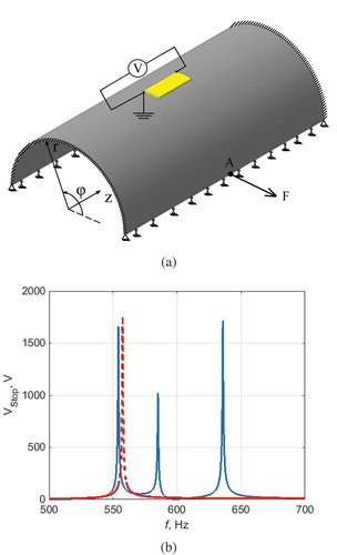
The first option (solid line) was found on the basis of the present algorithm under the condition of the best (optimal) realization of the piezoelectric properties within the frequency range from 500 to 700 Hz, which includes the first three vibration modes (point). The second option (dashed line) was found from the condition of achieving the maximal piezoelectric effect for only the first vibration mode.
The presented results show, that for the second option, the highest level of electric potential was achieved for the first mode. However, at the same time, the level of electric potential was negligibly small for the second and the third vibration modes. The first option for the piezoelectric element’s layout gave a bit lower level of electric potential in comparison to the second option. Nevertheless, it turned out to be close in value to the level of electric potential for the second and third vibration modes.
The next example shows the possibility of damping the first three vibration modes of the shell within the frequency range from 500 up to 700 Hz using a single-branch series RL-shunting circuit. The electrical circuit was modeled used two-nodal circuit-type finite elements CIRCU94 having a linear approximation of nodal unknowns [Citation43]. Here, the single piezoelectric element was optimally located according to the proposed algorithm in the point with the following coordinates of center of mass
,
m. The piezoelectric element’s electrodes were connected to the series external RL-circuit. The parameters of the circuit’s elements were defined according to the algorithm presented in [Citation41] (). For the specified frequency range from 500 up to 700 Hz, the value of resistance was found to be R = 4.92 kΩ and the value of inductance was found to be L = 6.30 H.
Figure 4. The sketch of the shell with the piezoelectric element and external electrical circuit.
In [Citation41], it was shown that for damping of the vibrations at several modes within any arbitrary frequency range, the rates of decay of vibrations should be equal (or very close in values) to each other for all modes and should be as high as possible.
According to the mathematical statement presented in [Citation44,Citation45], the solution to the problem of the natural vibrations of electroelastic bodies with external electric circuits is sought in the form (7)
Here, is the state vector containing the components of unknown displacements and the electric potential;
is the complex natural vibration frequency, where
is the circular frequency of vibrations, and
is damping index characterizing exponential decay rate of vibrations.
Representing (7) in trigonometric form (8) and considering that , we finally obtain:
Taking into account the complex conjugation of the obtained eigenvalues, the ones are chosen are those that have a negative imaginary part. This choice provides the damped character of vibration processes under consideration. From (8), it is seen that exactly the imaginary part of complex natural vibration frequency (or
) determines the damping properties of a structure (in this case, the rate of decay of the vibration amplitude).
The values of parameters of series external RL-circuit (resistance R = 4.92 kΩ and inductance L = 6.30 H) was calculated according to the approach represented in [Citation41] for the defined optimal location of piezoelectric element for the frequency range from 500 up to 700 Hz. These parameters of series RL-circuit provides vibration damping at all three natural vibration modes from the specified frequency range. The problem on natural vibrations for the structure under study with attached piezoelectric element connect to series RL-circuit having the calculated parameters was solved using the algorithm described in [Citation45]. The obtained natural vibration frequencies are presented in .
Table 5. The results of the solution to the problem of natural vibration for the shell with the attached piezoelectric element connected to the series RL-circuit.
For more clarity, the third column of contains values of the modal damping ratios (, where
is the natural vibration frequency of the shell without the piezoelectric element) for each natural vibration frequency under study. The maximal achievable modal damping ratios are represented in the fourth column of . These values of modal damping ratios are reached when the external circuit is tuned for damping only one single mode under the condition that the piezoelectric element is located optimally for this vibration mode.
The results presented in show that utilization of a piezoelectric element optimally located only for one vibration mode (considering the appropriate choice of parameters of the shunting circuit) allows achieving higher modal damping ratios than for the case of an optimally located piezoelectric element for its efficient performance at several frequencies (considering the choice of parameters of the shunting circuit according to the approach from [Citation41]).
However, the layout of the piezoelectric element considering its acceptable performance within some frequency range allows achieving a satisfactory level of vibration decay rate for all natural vibration modes from the specified frequency range using a single piezoelectric element connected to a single-branch shunt circuit. This aspect can be useful for practical implementation.
5. Conclusions
The algorithm for determining the optimal location of the piezoelectric element at the surface of an elastic deformable solid was proposed in the paper. The layout of the piezoelectric element according to this algorithm provides the best option for realization of the piezoelectric effect at all resonant frequencies within a specified frequency range. The combination of electromechanical coupling coefficients for the vibration modes included in the specified frequency range is proposed. A new parameter, which is as a parameter for qualitative estimation of the performance of a single piezoelectric element for multimodal operation was introduced. The highest value of the new introduced parameter defines the coordinates of the center of mass for the optimal location of the piezoelectric element.
Electromechanical coupling coefficients were calculated numerically on the basis of the solution of the problem of natural vibrations for electroelastic bodies using the finite element method. A condition for the unambiguous determination of the optimal location of the piezoelectric element was proposed for the cases when the highest values of the new introduced parameter were reached for more than one point.
The possibilities of the proposed algorithm were shown numerically using the example of a thin-walled half-cylindrical elastic shell. For this example, it was necessary to find the optimal location of the piezoelectric element at its surface which provided the optimal option for realization of the piezoelectric effect for different frequency ranges. The possibility of multimodal damping of vibrations with the aid of a single piezoelectric element and simple series RL-circuit with properly selected parameters of resistance and inductance was also demonstrated.
Acknowledgments
The reported study was funded by RFBR according to the research project № 18-31-00080.
Disclosure statement
No potential conflict of interest was reported by the authors.
Additional information
Funding
References
- N.W. Hagood and A. Von Flotow, Damping of structural vibrations with piezoelectric materials and passive electrical networks, J. Sound Vib. 146 (2) (1991), pp. 243–268. doi:10.1016/0022-460X(91)90762-9.
- J.J. Hollkamp, Multimodal passive vibration suppression with piezoelectric materials and resonant shunts, J. Intell. Mater. Syst. Struct. 5 (1994), pp. 49–56. doi:10.1177/1045389X9400500106.
- S.Y. Wu, Method for multiple mode shunt damping of structural vibration using a single PZT transducer, Smart Struct. Mater. Smart Struct. Int. Sys. Proc. SPIE. 3327 (1998), pp. 159–168.
- S.Y. Wu, Multiple PZT transducers implemented with multiple-mode piezoelectric shunting for passive vibration damping, Smart Struct. Mater. Passive Damp. Iso. Proc. SPIE. 672 (1999), pp. 112–122.
- S.Y. Wu and A.S. Bicos, Structural vibration damping experiments using improved piezoelectric shunts, Smart Struct. Mater. Passive Damp. Iso. Proc. SPIE. 3045 (1997), pp. 40–50.
- S. Behrens and S.O.R. Moheimani, Current flowing multiple mode piezoelectric shunt dampener, Proceedings of SPIE 4697, Smart Structures and Materials 2002: Damping and Isolation, San Diego, CA, 2002.
- S. Behrens, S.O.R. Moheimani, and A.J. Fleming, Multiple mode passive piezoelectric shunt dampener, Proc. IFAC Mechatronics 35 (2002), pp. 161–166.
- A.J. Fleming and S.O.R. Moheimani, Adaptive piezoelectric shunt damping, Smart Mater. Struct. 1 (2003), pp. 36–48. doi:10.1088/0964-1726/12/1/305.
- S. Behrens and S.O.R. Moheimani, Optimal resistive elements for multiple mode shunt damping of a piezoelectric laminate beam, 39th IEEE Conference on Decision and Control, 4 (2000), pp. 4018–4023, Sydney, NSW, Australia, 2000.
- T.H. Cheng and I.K. Oh, A current-flowing electromagnetic shunt damper for multi-mode vibration control of cantilever beams, Smart Mater Struct. 18 (2009), pp. 095036.
- S. Vidoli and F. dell’Isola, Vibration control in plates by uniformly distributed PZT actuators interconnected via electric networks, Eur. J. Mech./A Solids 20 (2001), pp. 435–456. doi:10.1016/S0997-7538(01)01144-5.
- M. Porfri, F. dell’Isola, and F.M.F. Mascioli, Circuit analog of a beam and its application to multimodal vibration damping, using piezoelectric transducers, Int. J. Circ. Theor. Appl. 32 (2004), pp. 167–198. doi:10.1002/cta.273.
- F. dell’Isola, E.G. Henneke, and M. Porfiri, Piezoelectromechanical structures: New trends towards the multimodal passive vibration control, Smart Struct. Mater. Passive Damp. Iso. Proc. SPIE. 5052 (2003), pp. 392–402.
- C. Maurini, F. dell’Isola, and D.D. Vescovo, Comparison of piezoelectronic networks acting as distributed vibration absorbers, Mech. Sys. Signal Proc. 18 (5) (2004), pp. 1243–1271. doi:10.1016/S0888-3270(03)00082-7.
- I. Giorgio, A. Culla, and D. Del Vescovo, Multimode vibration control using several piezoelectric transducers shunted with a multiterminal network, Arch. Appl. Mech. 79 (2009), pp. 859–879.
- F.A.C. Viana and V. Steffen Jr., Multimodal vibration damping through piezoelectric patches and optimal resonant shunt circuits, J. Of the Braz. Soc. Of Mech. Sci. & Eng. XXVIII (3) (2006), pp. 293–310. doi:10.1590/S1678-58782006000300007.
- F. Casadei, M. Ruzzene, L. Dozio, and K.A. Cunefare, Broadband vibration control through periodic arrays of resonant shunts: Experimental investigation on plates, Smart Mater Struct. 19 (2010), pp. 015002
- B. Lossouarn, J.-F. Deü, and M. Aucejo, Multimodal vibration damping of a beam with a periodic array of piezoelectric patches connected to a passive electrical network, Smart Mater Struct. 24 (2015), pp. 115037.
- F. Botta, D. Dini, S. Gentili, C. Schwingshackl, L. Di Mare, and G. Cerri, Optimal placement of piezoelectric plates to control multimode vibrations of a beam, Adv. Acoust. Vib. 2013 (2013), pp. 905160.
- F. Botta, A. Scorza, and A. Rossi, Optimal piezoelectric potential distribution for controlling multimode vibrations, Appl. Sci. 8 (2018), pp. 551. doi:10.3390/app8040551.
- Q. Huang, S. Chen, H. Pu, and N. Zhang, Optimal piezoelectric actuators and sensors configuration for vibration suppression of aircraft framework using particle swarm algorithm, Math. Prob. Eng. 2017 (2017), pp. 7213125. doi:10.1155/2017/7213125.
- E.F. Crawley and J. de Luis, Use of piezoelectric actuators as elements of intelligent structures, Aiaa J. 25 (10) (1987), pp. 1373–1385. doi:10.2514/3.9792.
- F. Bachmann, A. Bergamini, and P. Ermanni, Optimal piezoelectric positioning a strain-energy based finite element approach, J. Int. Mat. Syst. Struct. 23 (14) (2012), pp. 1575–1591. doi:10.1177/1045389X12447985.
- K. Ramesh and S. Narayanan, The optimal location of piezoelectric actuators and sensors for vibration control of plates, Smart Mater. Struct. 16 (2007), pp. 2680–2691. doi:10.1088/0964-1726/16/6/073.
- M. Hasanlu, A. Bagheri, and F. Najafi, Optimal placement of piezoelectric S/A for active vibration control of engineering structures by using controller design, J. Eng. Tech. 5 (2016), pp. 22–44.
- V. Gupta, M. Sharma, and N. Thakur, Optimization criteria for optimal placement of piezoelectric sensors and actuators on a smart structure: A technical review, J. Int. Mat. Syst. Struct. 21 (8) (2010), pp. 1227–1243. doi:10.1177/1045389X10381659.
- J. Ducarne, O. Thomas, and J.-F. Deu, Placement and dimension optimization of shunted piezoelectric patches for vibration reduction, J. Sound Vib. 331 (2013), pp. 3286–3303. doi:10.1016/j.jsv.2012.03.002.
- A. Belloli and P. Ermanni, Optimum placement of piezoelectric ceramic modules for vibration suppression of highly constrained structures, Smart Mater. Struct. 16 (2007), pp. 1662–1671.
- H. Ning, Optimal number and placements of piezoelectric patch actuators in structural active vibration control, Eng. Comput. 21 (2004), pp. 651–665. doi:10.1108/02644400410545218.
- A.M. Sadri, J.R. Wright, and R.J. Wynne, Modeling and optimal placement of piezoelectric actuators in isotropic plates using genetic algorithms, Smart Mater. Struct. 9 (1999), pp. 490–498. doi:10.1088/0964-1726/8/4/306.
- S.S. Rao and P.T. Shii, Optimal placement of actuators in actively controlled structures using genetic algorithms, AIAA J. 29 (6) (1991), pp. 942–943. doi:10.2514/3.10683.
- D. Chhabra, G. Bhushan, and P. Chandna, Optimal placement of piezoelectric actuators on plate structures for active vibration control via modified control matrix and singular value decomposition approach using modified heuristic genetic algorithm, Mech. Adv. Mater. Struct. 23 (3) (2016), pp. 272–280. doi:10.1080/15376494.2014.949932.
- I. Bruant, L. Gallimard, and S. Nikoukar, Optimization of piezoelectric sensors location and number using a genetic algorithm, Mech. Adv. Mater. Struct. 18 (7) (2011), pp. 469–475. doi:10.1080/15376494.2011.604600.
- J.M. Hale and A.H. Daraji, Optimal placement of sensors and actuators for active vibration reduction of a flexible structure using a genetic algorithm based on modified H infinity, J. Phys. 382 (2012), pp. 012036.
- S.T. Quek, S.Y. Wang, and K.K. Ang, Vibration control of composite plates via optimal placement of piezoelectric patches, J. Intell. Mater. Syst. Struct. 14 (4–5) (2003), pp. 229–245. doi:10.1177/1045389X03034686.
- K.R. Kumar and S. Narayanan, The optimal location of piezoelectric sensor and actuators for vibration control of plates, J. Smart Mater. Struct. 16 (2007), pp. 2680–2691. doi:10.1088/0964-1726/16/6/073.
- K. Morris and S. Yang, Comparison of actuator placement criteria for control of structures, J. Sound Vib. 353 (2015), pp. 1–18. doi:10.1016/j.jsv.2015.05.002.
- N.V. Sevodina, N.A. Yurlova, and D.A. Oshmarin, The optimal placement of the piezoelectric element in a structure based on the solution of the problem of natural vibrations, Solid State Phenom. 243 (2015), pp. 67–74. doi:10.4028/www.scientific.net/SSP.243.67.
- Q. Wang and C. Wang, A controllability index for optimal design of piezoelectric actuators in vibration control of beam structures, J. Sound Vib. 242 (3) (2001), pp. 507–518. doi:10.1006/jsvi.2000.3357.
- Z. Liu, D. Wang, H. Hu, and M. Yu, Measures of modal controllability and observability in vibration control of flexible structures, J. Guid. Contr. Dyn. 17 (6) (1994), pp. 1377–1380. doi:10.2514/3.21363.
- D.A. Oshmarin, M.A. Iurlov, N.V. Sevodina, and N.A. Iurlova, Passive multimodal damping of vibrations in structures with piezoelectric elements and external electric circuits, 8th ECCOMAS Thematic Conference on Smart Structures and Materials (SMART 2017) and 6th International Conference on Smart Materials and Nanotechnology in Engineering. pp. 1125–1136, , Madrid, Spain, 2017.
- N.A. Iurlova, V.P. Matveenko, D.A. Oshmarin, N.V. Sevodina, and M.A. Yurlov, Layout optimization of piezoelectric elements with external electric circuits in smart constructions based on solution of the natural vibrations problem, VIIth ECCOMAS Congress 2016, Crete, Greece, 2016.
- Ansys 17.2 Documentation, SAS IP, Inc, Canonsburg, 2016.
- V.P. Matveenko, N.A. Iurlova, D.A. Oshmarin, N.V. Sevodina, and M.A. Iurlov, An approach to determination of shunt circuits parameters for damping vibrations, Int. J. Smart and Nano Mater. 9 (2) (2018), pp. 135–149. doi:10.1080/19475411.2018.1461144.
- V.P. Matveenko, D.A. Oshmarin, N.V. Sevodina, and N.A. Yurlova, Natural vibration problem for electroviscoelstic body with external electric circuits and finite-element relations for its numerical implementation, Comp. Cont. Mech. 9 (2016), pp. 476–485.