
ABSTRACT
In this work, we printed a Nafion precursor membrane by fused deposition modeling (FDM) rapid prototyping technology and further fabricated IPMCs by electroless plating. The ion-exchange capacity of the Nafion membrane was tested, and the morphology of IPMCs was observed. The electro-mechanical properties of IPMCs under AC voltage inputs were studied, and grasping experiments were performed. The results show that the Nafion membrane after hydrolysis has a good ion-exchange ability and water-holding capacity. SEM observed that the thickness of the IPMC’s electrode layer was about 400 nm, and the platinum layer was tightly combined with the substrate membrane. When using a square wave input of 3.5 V and 0.1 Hz, the maximum current of IPMCs reached 0.30 A, and the displacement and blocking force were 7.57 mm and 10.5 mN, respectively. The new fabrication process ensures the good driving performance of the printed IPMC. And two pieces of IPMCs can capture the irregular objects successfully, indicating the feasibility of printing IPMCs by FDM technology. This paper provides a new and simple method for the fabrication of three-dimensional IPMCs, which can be further applied in flexible grippers and soft robotics.
GRAPHICAL ABSTRACT
1. Introduction
Ionic polymer–metal composites (IPMCs), one kind of ionic electroactive polymers, have the advantages of low driving voltage (usually 1~5 V), large deformation, light weight, no noise, high flexibility, and good biocompatibility [Citation1–5]. The intermediate layer of IPMCs is ion–exchange resin (typically perfluorosulfonic acid cation exchange Nafion membrane), while the two side layers of IPMCs are noble metal electrodes (such as platinum and gold) formed by electroless plating [Citation6]. When voltage is applied on both sides of IPMCs, the hydrated cations inside IPMCs migrate to the cathode under the action of electric field, causing the difference in ionic concentration on both sides of the membrane. This difference results in an expanded cathode and a contracted anode, showing a bending phenomenon [Citation7,Citation8], and IPMCs can produce reciprocating oscillation under alternating current (AC) input. In addition, using electrostatic power to drive IPMCs is also a possible approach [Citation9]. But the voltage of the nanogenerator is high and the current and power are small [Citation10]. In order to drive the IPMCs, the nanogenerator must have a voltage of 1~10 V and power of several watts [Citation11–13]. IPMCs are widely used in medical and bionic robot fields, including medical catheters [Citation11,Citation14–16], surgical microforceps [Citation12], heart-compression devices [Citation17], underwater robots and biomimetic fish [Citation18,Citation19], driving of imitation gecko toes [Citation20], and flapping devices of bionic insects [Citation13]. IPMCs are traditionally fabricated by electroless plating based on the commercial recast membrane, which has some shortcomings such as a long fabrication period, a tedious process, a single shape and an uncontrollable thickness. So the commercial recasted membrane greatly limits the application and development of IPMC. Therefore, multitudinous scholars have searched for new methods to fabricate IPMCs. For example, Park et al. [Citation21], Bonomo et al. [Citation22], Tiwari et al. [Citation23], and Lee et al. [Citation24] extruded Nafion particles or multiple Nafion membranes into thicker Nafion membranes by hot-pressing method, but this method requires making molds in advance and the production process is tedious. Trabia et al. prepared a Nafion membrane by spraying, requiring a relative mold in advance, but this process takes a long time to form Nafion membrane and also causes serious swellings [Citation25]. Malone et al. prepared IPMCs using a mixture of Nafion solution, alcohol, and water as the intermediate layer and a mixture of silver particles and Nafion solution as the electrode material. However, this method has difficulty in controlling the shape of the molding and the specimen has poor surface quality and deformation performance [Citation26]. Luo et al. achieved the printing of electrode layer with single-wall carbon nanotubes and Nafion-intermediate layer by means of direct writing technology, but the specimen prepared by this method is partially fractured [Citation27].
Fused deposition modeling (FDM) rapid prototyping technology can print complex shapes or structures with the advantages of fast printing speed, low cost, and high reliability, better compatibility with ordinary materials and less post-processing [Citation28]. In addition, the FDM technology enables fabricating continuous-fiber composites without the use of molds and may become a standard method for next-generation composite fabrication[Citation29]. Therefore, FDM is one of the most commonly used methods in additive manufacturing (AM) [Citation30]. Carrico et al. firstly printed a Nafion membrane with fused filament fabrication technology, prepared metal electrodes using an electroless plating method, and studied the output displacement of the IPMC sample, indicating that 3D printing provides a new method for fabricating soft robots, but the blocking force performance of 3D printed IPMCs was not studied [Citation31]. Trabia et al. compared the water content, ion-exchange capacity, and the thermal decomposition temperature of Aquivion and Nafion materials and then printed the Aquivion substrate membrane by fused filament fabrication. Aquivion-based IPMCs were prepared by electroless plating method. It indicates that Aquivion as a potential candidate can be used for 3D printing [Citation32,Citation33].
In this paper, the Nafion substrate membrane was fabricated by FDM technology, on which two platinum electrodes were prepared by electroless plating method. Ion-exchange capacity (IEC) of printed Nafion membranes were conducted. We observed the scanning electron microscope (SEM) surface and cross-section images of IPMCs. The working electric current, displacement, and blocking force of the printed IPMCs were tested under different voltages. Finally, a grasping experiment was carried out successfully.
2. Materials and methods
2.1. Materials
Nafion R1100 precursor beads were obtained from Ion Power, Inc., (New Castle, DE). Methylene blue, and [Pt(NH3)4]Cl2 were obtained from Sigma Aldrich (St. Louis, MO, USA). NH3·H2O, NaOH, DMSO, KOH, and CuSO4 · 5H2O were obtained from Sinopharm Chemical Reagent Co., Ltd. (Shanghai, China). NaBH4, NH2OH·HCl, and N2H4·H2O were purchased from Nanjing Chemical Reagent Co., Ltd (Nanjing, China). All other reagents were reagent grade and used without further purification.
2.2. Fabrication process
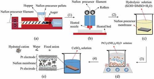
The preparation of IPMC actuator by FDM method mainly includes the following steps, which can be seen in . The first step is to prepare Nafion precursor filament. The Nafion precursor pellets were extruded at the melting temperature of 250°C into the Nafion precursor filament with a diameter of 1.75 mm for printing. The second step is to print the Nafion precursor membrane. A modeling software was used to build the three-dimensional model of Nafion membrane and the corresponding printing parameters were established [Citation29,Citation30]. The height of each layer was 0.2 mm with a 100% infill, printing speed was 20 mm/s, extrusion rate was 100%, printer nozzle diameter was 0.6 mm, and the temperatures of nozzle and hot bed were 280°C and 120°C, respectively. The Nafion precursor membrane was printed by a 3D printer layer by layer. The third step is to hydrolyze Nafion precursor membrane. The Nafion precursor membrane printed in the second step was hydrolyzed in the mixture of 15 wt % KOH, 35 wt % DMSO, and 50 wt % deionized water at 80°C. The time of hydrolysis was determined by the membrane thickness, and the hydrolysis rate was approximately 1.3 μm/min [Citation34]. The fourth step is to generate platinum electrodes on both sides of Nafion membrane by electroless plating [Citation20,Citation35]. The fifth step is to introduce Cu2+ into IPMC sample by immersing it in an appropriate salt solution (0.5 M CuSO4) at a moderate temperature for 24 h. Copper-ion-driven IPMCs can repair the damaged electrode by itself, reduce the surface resistance of the electrode, and improve its actuation performance [Citation35].
Figure 1. Schematic diagram of IPMC specimen fabrication by FDM technology: (a) Fabrication process of Nafion precursor filament. (b) Nafion precursor membrane printed by a 3D printer. (c) The hydrolysis process exchanges the sulfonyl fluoride group to a sulfonate end group. (d) Prepare Pt electrodes by an electroless plating process. (e) Ion exchange process
2.3 Test
The IEC of the Nafion membrane was calculated by acid-base titration method, and the hydrolyzed Nafion membrane was dyed by methylene blue.
Scanning electron microscope (SEM) (Zeiss Sigma, Germany) images were used to observe the surface morphology and cross-section structures of the printed IPMCs. The cross-sections of all specimens were obtained by low-temperature fracturing method, and all specimens were coated with gold particles before SEM observations.
The printed IPMCs were cut into strips with a dimension of 25 mm × 5 mm × 0.6 mm (length × width × thickness). The thickness and mass of IPMCs were measured by a vernier calliper and an analytical balance (AL204, Mettler-toledo, Switzerland), respectively. The electric current, displacement, and blocking force of IPMCs were measured under an AC electric field at 0.1 Hz, and all experiments were performed in air at room temperature.
The experimental setup comprised a signal generator (SP1651, Sample, China), a laser displacement sensor (LK-G80, Keyence, Japan), a load cell (Q84X5X12-05, Zhonghang Electronic Measuring Instruments Co., Ltd. China), and a current measuring device. The load cell was fixed and attached to one end of the specimen during the process of testing blocking force. The laser beam of laser displacement sensor that collected the displacement of IPMCs during the actuation process was perpendicular to the surface of IPMC and projected at a spot 20 mm from the fixed edge of the IPMC. The current sensor was used to record the current of the IPMCs. In the test, one end of the IPMCs was fixed with a conductive clamp, while the other end acted as a free section to measure the displacement and blocking force.
3. Results and discussion
3.1. IEC test
The IEC that represents the capacity of ion-exchange reaction was greatly significant to the actuation performance of IPMCs. Because the end of the side chain of Nafion precursor material is a sulfonyl fluoride group (–SO2F), this material has no ion-exchange capability and cannot be used as an ion-exchange membrane to manufacture IPMCs. The Nafion precursor material must be hydrolyzed to switch the end group to an acid form once the shapes are made.
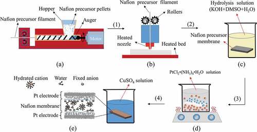
shows the effect of hydrolysis time on Nafion precursor specimens. The black area shows the hydrolyzed part stained with methylene blue. And the appearance of the unhydrolyzed Nafion precursor specimen is creamy white. As the hydrolysis time increased, the Nafion precursor specimen was gradually hydrolyzed from the outside to the inside and the diameter of the filament gradually increased. The diameters of the two Nafion precursor filaments were 1.1 mm and 2.2 mm, respectively, before hydrolysis and 1.39 mm and 2.83 mm, respectively, after complete hydrolysis. The filament diameter expansion rates were 26.36% and 28.64%, respectively. The reason is that the K+ and water molecules combined to form water clusters, swelling the Nafion membrane during the hydrolysis process, which agrees with the mechanism described by Elliott [Citation34].
Figure 2. (a) The relationship between the thickness of precursor specimen and hydrolysis time; (b) the comparison of the IEC between the printed Nafion membrane and commercial membrane
Furthermore, we calculated the IEC of the hydrolyzed Nafion membrane by IEC experiment and compared with commercial membranes. The IEC of the hydrolyzed Nafion membrane is 0.81 meq·g−1, and this value is higher than that of commercial Nafion-115 (0.71 meq·g−1), Nafion-117 (0.71 meq·g−1), and Nafion-1110 (0.78 meq·g−1) as shown in . This further indicates that 3D-printed Nafion membrane has a better IEC, ensuring the effectiveness and feasibility of this new printing method for IPMC preparation.
3.2 Water content test
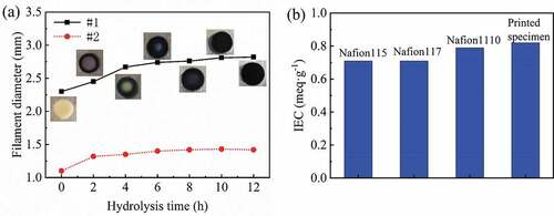
The water-holding capacity of IPMCs is one of the most important parameters for evaluating IPMC performance. As the water loss rate of IPMCs decreases, the working time of the hydrated cations inside IPMCs increases, so the good water-holding capacity can prolong the working time of IPMCs in air. shows the change in mass and thickness of IPMCs when it is placed in air after completely absorbing water. It shows that as the time of IPMCs leaving water increases, its mass and thickness gradually decrease, which is the result of the gradual loss of water inside IPMCs. For example, when the IPMCs were placed in air for 40 minutes, the mass and thickness of the IPMCs decreased to 0.1123 g and 0.61 mm, respectively. As the time that IPMCs placed in air increased further, the mass and thickness of the IPMCs continued to decrease. This result indicates that the water inside the IPMCs has not completely evaporated after being placed in air for 40 min. The results also show that the printed IPMC specimen has a good water-holding ability that is conducive to extending the working time of IPMCs in air and improving its actuation performance.
Figure 3. Thickness and mass of IPMC in air at room temperature vs. time
3.3 Morphology observations
shows the printed IPMC and its electrode morphology. It can be seen from that the top layer of the printed IPMC consists of obvious groove structures caused by the in-fill pattern during the process of printing Nafion membrane. It is easy to appear undulated or ribbed features during printing, which has been reported in reference [Citation31]. In the next work, we will improve this situation by reducing the printing speed and increasing the extrusion rate during printing. Besides, it can be seen in that the in-fill pattern on the bottom layer of printed IPMC is not obvious. Then the profiles of the top layer () and bottom layer ( of the printed IPMC were measured by 3D profiler (KEYENCE VR-5000, Japan), the red trace represents the measurement path. The profiles of the printed IPMC are shown in and . It is not difficult to see from and that the top layer of IPMC has groove structures (as shown in , the depth and width of the groove structure on the top layer are greater than those on the bottom layer, and the bottom layer of the printed IPMC looks flatter than the top layer. The reason for this difference is that the bottom layer of Nafion membrane is firmly attached to the hot bed of the 3D printer and the extrusion pressure during the printing process makes the bottom filling pattern cannot stand out, so there is no obvious groove structure on the bottom layer of the printed Nafion membrane. This difference may lead to asymmetry in the bending of the printed IPMC.
Figure 4. Currents vs. time under AC voltage with a frequency of 0.1 Hz. The actual current changes of the IPMC under square wave input (a) and sinusoidal input (b); the maximum currents of IPMCs under square wave input (c) and sinusoidal input (d)
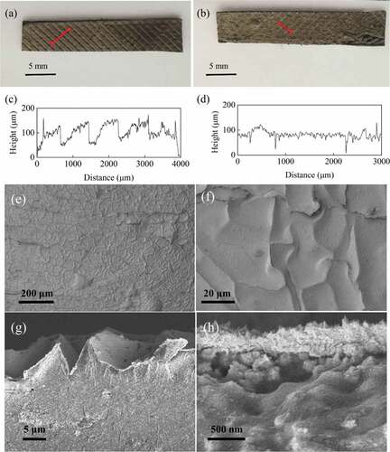
It can be seen from and that there are folds on the electrode surfaces of the printed IPMCs. This is a common phenomenon, which was described in references [Citation11] and [Citation13], and the IPMC prepared using commercial membrane or cast membrane also has such folds. The electrode layer of the printed IPMC also has the groove structure, as shown in . The reason for this phenomenon is that the printed Nafion membrane was not polished before electroless plating. And the groove structure increases the specific surface area of the printed IPMC and reduces the thickness of the platinum electrode layers under the same conditions of platinum ion adsorption. It can be seen from that the electrode thickness of the printed IPMC is only 400 nm, which is smaller than the electrode thickness (12 μm) of the commercial recast membrane in references [Citation13] and [Citation20]. In the next work, we will further improve the surface quality of the printed membrane and increase the thickness of the Pt electrode layer by reducing the printing speed, adjusting the extrusion rate and polishing the printed Nafion membrane. Although there are folds on the electrode surface of the printed IPMC, the electrode remains the compact structure, as shown in . In addition, it can be seen that the Pt electrode layer and Nafion membrane are closely bonded in . And this may be the reason why the fabricated IPMC has the characteristics of metallic luster.
In summary, the groove structure on the printed membrane increases the specific surface area of the printed IPMC and reduces the thickness of the Pt electrode layer. However, the electrode of the printed IPMCs has a compact structure and metallic luster, which proves that the printed IPMC can maintain good electrode performance.
3.4 The current
IPMCs are electro-actuated actuators, and the electric current is one of the most important performances. The electric current is caused by the migration of the cations within IPMCs [Citation36].
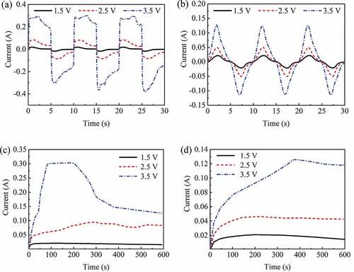
and shows the actual current characteristics of IPMCs under square wave input and sinusoidal input, respectively. and shows the variation of the maximum current of IPMCs versus the operating time, respectively. It can be seen from and that the operating current of IPMCs gradually increases with increased applied voltage amplitude. When the voltage amplitude increases to 3.5 V, the maximum operating currents of IPMCs under square wave input and sinusoidal input were 0.30 A (shown in ) and 0.13 A (shown in ), respectively. Under square wave input and sinusoidal input with the same frequency and amplitude, the operating current of IPMCs under square wave input was higher than that under sinusoidal input. However, the current variation of IPMCs under sinusoidal input is more stable especially under 3.5 V AC, as shown in and . In addition, as working time increases, the maximum operating current of IPMCs tends to increase and then decrease. For example, when the IPMCs work at a square wave input of 3.5 V for 200 s (as shown in ), its current starts dropping significantly. When the IPMCs work under a sinusoidal input of 3.5 V for about 400 s (as shown in ), its current has a gentle decrease, indicating a sinusoidal input can keep the current stable for a longer time. The reason for this difference is that the square wave input has a higher power density than the sinusoidal input with the same frequency and amplitude. When square wave input is applied to the IPMC, the hydrated cations inside IPMC would migrate quickly and increase the operating current of IPMC. But the large square wave input also aggravates the loss of water inside IPMC, which lead to the decrease of the movable hydrated cations inside IPMC and further cause a large drop in operating current. When the IPMCs work under square wave inputs and sinusoidal inputs of 1.5 V and 2.5 V, its operating current is more stable. As a result, when IPMCs work under a low voltage, the internal water molecules evaporate slowly and the hydrated cations can keep working for a long time.
Figure 5. Currents vs. time under AC voltage with a frequency of 0.1 Hz. The actual current changes of the IPMC under square wave input (a) and sinusoidal input (b); the maximum currents of IPMCs under square wave input (c) and sinusoidal input (d)
3.5 Actuation performance
The displacement and blocking force of IPMCs are two important parameters used to evaluate the actuation performance. The displacement and blocking force of IPMCs were measured under AC voltage inputs to characterize the actuation performance of 3D-printed IPMCs.
shows the displacement characteristics of IPMCs under square wave input and sinusoidal input at a frequency of 0.1 Hz. It can be seen from and that as the applied voltage increases, the displacement of the IPMCs gradually increases. When the voltage increases to 3.5 V, the peak-to-peak values of displacement of the printed IPMCs were 10.5 mm under square wave input and 6.5 mm under sinusoidal input, respectively. The unidirectional maximum displacements of IPMCs were 7.57 mm under square wave input and 5.13 mm under sinusoidal input, respectively, which was similar to the displacement of conventional IPMCs in the literature [Citation36]. It can be seen from the above results that printed IPMCs have good displacement performance. Interestingly, the displacement of IPMC was not symmetrical oscillation under either square wave input () or sinusoidal input (). This phenomenon might be due to the unpolished printed Nafion membrane before electroless plating, resulting in the different grooves structure on the sides of the printed IPMC. This phenomenon also provided a new idea for the fabrication of IPMCs with asymmetric oscillation for some special application.
Figure 6. Displacement vs. time under AC voltage with a frequency of 0.1 Hz. The actual displacement changes of the IPMC under square wave input (a) and sinusoidal input (b); Maximum displacement of IPMC under square wave input (c) and sinusoidal input (d)
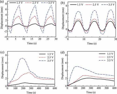
It can be seen from and that the maximum displacement of IPMCs under AC voltage inputs firstly increases and then decreases with the increase of working time. Under square wave inputs of 1.5 V, 2.5 V and 3.5 V, IPMC reaches its maximum displacement between 180 s and 270 s as shown in . The time for IPMC to reach its maximum displacement is between 100 s and 250 s under sinusoidal inputs of 1.5 V, 2.5 V and 3.5 V as shown in . After reaching the maximum displacement, the displacement of IPMC has a fast decrease with the increase of voltage input. As shown in and , the displacement of IPMC under AC voltage inputs can work about 250 s, and maintain 80% maximum displacement, which indicates that the IPMC prepared by FDM technology has good displacement performance.
shows the blocking force characteristics of IPMCs under square wave input and sinusoidal input at a frequency of 0.1 Hz. It can be seen from that the blocking force of IPMC increases with the increase of the voltage input. Under square wave input ( and ) of 1.5 V, 2.5 V and 3.5 V, the blocking forces of IPMC were 3.5 mN, 5.0 mN and 10.5 mN, respectively. And under sinusoidal input ( and ) of 1.5 V, 2.5 V and 3.5 V, the blocking force of IPMC were 2.0 mN, 3.0 mN and 4.5 mN, respectively. The blocking force of IPMC under square wave input was 1.75 ~ 2.33 times than that under sinusoidal input. It also indicates that the square wave input was more effective in promoting the blocking force of IPMC.
Figure 7. Blocking force vs. time under AC voltage with a frequency of 0.1 Hz. The actual blocking force changes of the IPMC under square wave input (a) and sinusoidal input (b); the maximum blocking force of IPMC under square wave input (c) and sinusoidal input (d)
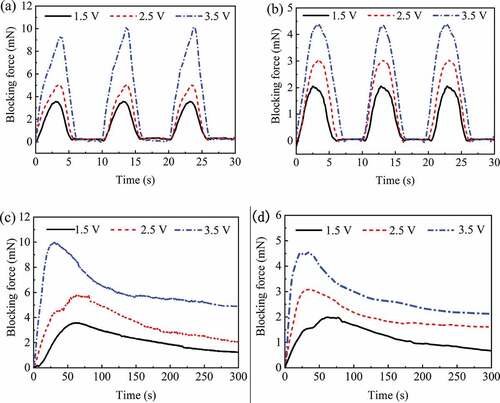
It can be seen from and that the maximum blocking force of IPMC firstly increases and then decreases with the increase of working time. The time for IPMC to reach the maximum blocking force was between 25 s and 75 s under both square wave input and sinusoidal input of 1.5 V, 2.5 V and 3.5 V. However, the blocking force of IPMC under the square wave input was higher than that under sinusoidal input as shown in and . It shows that IPMC can maintain a better blocking force performance under square wave input than that under sinusoidal input.
3.6 Application to gripper
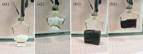
Overall, the IPMCs prepared by FDM technology in this paper have better displacement and blocking force performance under square wave inputs. To further investigate the actuation performance of the IPMCs prepared, we used two IPMCs to fabricate a flexible gripper, and tested its grasping performance, as shown in . The experiment shows that two IPMCs can successfully grasp the irregular objects under square wave input of 3.5 V. The phenomenon provides a new idea for flexible grasping design in future work.
Figure 8. The flexible grippers made by two IPMCs: (a1, b1) the initial state of the gripper; (a2, b2) the state of grasping the object
4. Conclusions
In this work, the Nafion precursor membrane was successfully fabricated by FDM technology and the IPMC was further obtained by electroless plating. The new fabrication process which greatly saves the time and gets rid of limitation of mold ensures a good driving performance of the printed IPMC. The results show that the IEC of hydrolyzed Nafion membrane is 0.81 meq·q−1 and it is better than the commercial membranes, which ensures the effectiveness of IPMC fabrication. The printed IPMC can be placed in air for more than 40 min, which indicates that it has a good water-holding ability. SEM images show that the printed IPMC has a compact electrode structure and metallic luster. The groove structure of the printed IPMC effectively increases the specific surface area of the platinum electrodes, and the thickness of the electrode layer was about 400 nm. The actuation performance tests show that the maximum operating current, displacement, and blocking force of the printed IPMCs were 0.30 A, 7.57 mm, and 10.5 mN under square wave input of 3.5 V and 0.1 Hz, respectively, which were better than those under sinusoidal input. Based on the printed IPMC, a flexible gripper with two printed IPMCs was developed and the flexible gripper could successfully grasp the irregular objects, which verifies the feasibility of IPMCs fabricated by FDM technology. The results also provide a new and simple method for the fabration of IPMCs with complex shapes or structures in future. In next work, we will optimize the parameters such as printing speed and extrusion rate to improve the surface quality of the printed IPMC.
Acknowledgments
The authors are deeply grateful for financial support from the Natural Science Foundation of Jiangsu Province (BK20160793), the National Natural Science Foundation of China (U1637101) and NSFC (51605220), and Open Funding from the Shanghai Key Laboratory of Spacecraft Mechanism, Open Project funding form Hubei Key Laboratory of Hydroelectric Machinery Design & Maintenance (2017KJX11).
Disclosure statement
No potential conflict of interest was reported by the author(s).
Additional information
Funding
References
- Baughman RH. Playing nature’s game with artificial muscles. Science. 2005;308(5718):63–65.
- Haines CS, Lima MD, Li N, et al. Artificial muscles from fishing line and sewing thread. Science. 2014;343(6173):868–872. .
- Lima MD, Li N, De Andrade MJ, et al. Electrically, chemically, and photonically powered torsional and tensile actuation of hybrid carbon nanotube yarn muscles. Science. 2012;338(6109):928–932. .
- Nemat-Nasser S, Wu Y. Comparative experimental study of ionic polymer-metal composites with different backbone ionomers and in various cation forms. J Appl Phys. 2003;93(9):5255–5267.
- Li JZ, Ma WJ, Song L, et al. Superfast-response and ultrahigh-power-density electromechanical actuators based on hierarchal carbon nanotube electrodes and chitosan. Nano Lett. 2011;11(11):4636–4641. .
- Yan YS, Santaniello T, Bettini LG, et al. Electroactive ionic soft actuators with monolithically integrated gold nanocomposite electrodes. Adv Mater. 2017;29(23):1606109. .
- Nemat-Nasser S. Micromechanics of actuation of ionic polymer-metal composites. J Appl Phys. 2002;92(5):2899–2915.
- Kim J, Bae SH, Kotal M, et al. Soft but powerful artificial muscles based on 3D graphene-CNT-Ni Heteronanostructures. Small. 2017;13(31):1701314. .
- Yang D, Kong XX, Ni YF, et al. Ionic polymer-metal composites actuator driven by the pulse current signal of triboelectric nanogenerator. Nano Energy. 2019;66:104139.
- Lei R, Shi YS, Ding YF, et al. Sustainable high-voltage source based on triboelectric nanogenerator with a charge accumulation strategy. Energ Environ Sci. 2020;13(7):2178–2190. .
- He QS, Huo K, Xu XR, et al. The square rod-shaped ionic polymer-metal composite and its application in interventional surgical guide device. Int J Smart Nano Mater. 2020;11(2):159–172. .
- Feng GH, Chen RH. Fabrication and characterization of arbitrary shaped μIPMC transducers for accurately controlled biomedical applications. Sensor Actuat A-Phys. 2008;143(1):34–40.
- Ma SQ, Zhang YP, Liang YH, et al. High-performance ionic-polymer-metal composite: toward large-deformation fast-response artificial muscles. Adv Funct Mater. 2019;30(7):1908508. .
- Fang BK, Lin CCK, Ju MS. Development of sensing/actuating ionic polymer-metal composite (IPMC) for active guide-wire system. Sensor Actuat A-Phys. 2010;158(1):1–9.
- Ruiz S, Mead B, Palmre V, et al. A cylindrical ionic polymer-metal composite-based robotic catheter platform: modeling, design and control. Smart Mater Struct. 2014;24(1):015007. .
- Yoon WJ, Reinhall PG, Seibel EJ. Analysis of electro-active polymer bending: a component in a low cost ultrathin scanning endoscope. Sensor Actuat A-Phys. 2007;133(2):506–517.
- Shahinpoor M, Kim KJ. Ionic polymer–metal composites: IV. Industrial and medical applications. Smart Mater Struct. 2004;14(1):197–214.
- Chen Z, Tan XB. Monolithic fabrication of ionic polymer-metal composite actuators capable of complex deformation. Sensor Actuat A-Phys. 2010;157(2):246–257.
- Palmre V, Hubbard JJ, Fleming M, et al. An IPMC-enabled bio-inspired bending/twisting fin for underwater applications. Smart Mater Struct. 2012;22(1):014003. .
- He QS, Yang X, Wang ZY, et al. Advanced electro-active dry adhesive actuated by an artificial muscle constructed from an ionic polymer metal composite reinforced with nitrogen-doped carbon nanocages. J Bionic Eng. 2017;14(3):567–578. .
- Park JH, Lee SW, Song DS, et al. Highly enhanced force generation of ionic polymer–metal composite actuators via thickness manipulation. ACS Appl Mater Inter. 2015;7(30):16659–16667. .
- Bonomo C, Bottino M, Brunetto P, et al. Tridimensional ionic polymer metal composites: optimization of the manufacturing techniques. Smart Mater Struct. 2010;19(5):055002. .
- Tiwari R, Kim KJ. Disc-shaped ionic polymer metal composites for use in mechano-electrical applications. Smart Mater Struct. 2010;19(6):065016.
- Lee SJ, Han MJ, Kim SJ, et al. A new fabrication method for IPMC actuators and application to artificial fingers. Smart Mater Struct. 2006;15(5):1217–1224. .
- Trabia S, Hwang T, Kim KJ. A fabrication method of unique Nafion® shapes by painting for ionic polymer-metal composites. Smart Mater Struct. 2016;25(8):085006.
- Malone E, Lipson H. Freeform fabrication of ionomeric polymer-metal composite actuators. Rapid Prototyping J. 2006;12(5):244–253.
- Luo B, Chen HL, Zhu ZC, et al. Printing single-walled carbon nanotube/Nafion composites by direct writing techniques. Mater Design. 2018;155(5):125–133. .
- Truby RL, Lewis JA. Printing soft matter in three dimensions. Nature. 2016;540(7633):371–378.
- Matsuzaki R, Ueda M, Namiki M, et al. Three-dimensional printing of continuous-fiber composites by in-nozzle impregnation. Sci Rep. 2016;23058(6):1–7.
- Walker DA, Hedrick JL, Mirkin CA. Rapid, large-volume, thermally controlled 3D printing using a mobile liquid interface. Science. 2019;366(6463):360–364.
- Carrico JD, Leang KK. Fused filament 3D printing of ionic polymer-metal composites for soft robotics. Smart Mater Struct. 2015;24(12):125021.
- Trabia S, Olsen Z, Kim KJ. Searching for a new ionomer for 3D printable ionic polymer–metal composites: aquivion as a candidate. Smart Mater Struct. 2017;26(11):115029.
- Trabia S, Choi K, Olsen Z, et al. Understanding the thermal properties of precursor-ionomers to optimize fabrication processes for ionic polymer-metal composites (IPMCs). Materials. 2018;11(5):1–12. .
- Elliott JA, James PJ, McMaster TJ, et al. Hydrolysis of the Nafion® precursor studied by X-ray scattering and in-situ atomic force microscopy. e-Polymers. 2001;1(1):1–11. .
- Wang ML, Yu M, Lu MY, et al. Effects of Cu2+ counter Ions on the actuation performance of flexible ionic polymer metal composite actuators. J Bionic Eng. 2018;15(6):1047–1056. .
- He QS, Yu M, Song LL, et al. Experimental study and model analysis of the performance of IPMC membranes with various thickness. J Bionic Eng. 2011;8(1):77–85.