
 ?Mathematical formulae have been encoded as MathML and are displayed in this HTML version using MathJax in order to improve their display. Uncheck the box to turn MathJax off. This feature requires Javascript. Click on a formula to zoom.
ABSTRACT
Commercial Chinese ink was employed to disperse pristine vapor-grown carbon nanofibers (VGCNFs) in aqueous suspensions via horizontal ball milling. The obtained suspension was used to fabricate conductive paper-based composites through filtration-deposition onto filter paper. It was found that the carbon black particles from the Chinese ink helped separate VGCNFs and acted as connection points between the VGCNFs, while the glue reinforced the conduction network. Thus, the VGCNF-ink/paper ternary composite showed sufficiently low sheet resistance. With merely 2.5 mg·cm−2 VGCNFs, the sheet resistance could be reduced to 4.5 Ω·sq−1. As a proof of concept, these paper-based composites were directly used as electrodes of solid-state symmetric electronic double-layer capacitors (EDLCs) and the substrate for the electrodeposition of MnO2 to achieve higher electrochemical performances. The EDLCs fabricated with 2.5 mg·cm−2 VGCNFs showed a specific capacitance of 224 mF·cm−2 at a current density of 1 mA·cm−2, which was retained by 86.4% after 10,000 charge-discharge cycles. Moreover, thanks to the high electrical conductivity and the porous structure, the MnO2 decorated paper-based composites exhibited dramatically enhanced specific capacitance. It is believed that our finding offers an idea to directly utilize commercial Chinese ink for the fabrication of electrode materials.
Introduction
Supercapacitors (also known as electrochemical capacitors or ultracapacitors) are highly valued by researchers as a promising energy storage strategy to meet ever-growing needs of clean energy, because of their unique features, especially in terms of superior power density, fast charge-discharge rate, long life span [Citation1–6]. Depending on the energy storage mechanism, supercapacitors can be divided into electrical double-layer capacitors (EDLCs) and pseudocapacitors. EDLCs usually employ carbon materials with large specific surface area as electrodes and the capacitance arises from the pure electrostatic charge accumulation at electrode–electrolyte interface [Citation7]. By contrast, pseudocapacitors employ metal oxides/nitrides [Citation8] or conducting polymers [Citation9,Citation10] as main electrode materials, taking advantage of the fast and reversible Faradaic charge reactions of electroactive species occurring on electrode surface. In general, pseudocapacitors demonstrate higher capacitance than EDLCs, but meanwhile they suffer from higher equivalent series resistance (ESR) and short-cycle life. It has been a trend to incorporate carbon materials with electroactive species to obtain supercapacitors with balanced performance [Citation11].
Vapor-grown carbon nanofibers (VGCNFs) is one kind of one-dimensional carbon nanomaterials. Analogous to carbon nanotubes (CNTs), VGCNFs possess many appealing properties, such as the high aspect ratio, high electrical conductivity and good electrochemical stability. However, compared with CNTs, VGCNFs have more microstructure defects, larger fiber sizes, and lower bulk density [Citation12]. Wet chemistry on the basis of CNT/VGCNF suspensions is a simple and efficient approach to preparing electrode materials for supercapacitors. Nevertheless, pristine VGCNFs suffer from low dispersity due to their high aspect ratio and poor interfacial interaction with aqueous or organic solvents, which drastically reduces their performance. To tackle this problem, pristine CNTs or VGCNFs are commonly subjected to surface functionalization by strong acids or surfactants in prior to use [Citation13–15]. Although effective to some extent, these pre-treatments tend to undermine the intrinsic electrical conductivity and electrochemical stability, and suffer from one or more shortcomings, such as laborious processes, high cost, high risk, and low efficiency. Thus, it is always desirable to find alternative methods to develop high-performance electrode materials [Citation16,Citation17].
Chinese ink is rarely applied as a material for scientific research, though it has a long history of being a black pigment for calligraphy and drawing. Technically speaking, Chinese ink is a kind of colloidal suspension (i.e. sol), with water as the continuous phase and glue-coated carbon black particles as the dispersed phase. Chinese ink can be regarded as a ready-made suspension of carbon nanomaterials owing to the contained carbon black. The homogeneity of Chinese ink inspires us to apply it as a starting material for research.
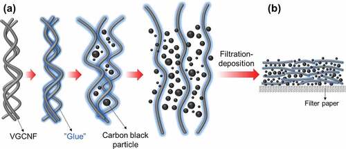
In view of the good stability of carbon black particles in Chinese ink, we assumed that Chinese ink could be used to facilitate the dispersion of VGCNFs, by taking advantage of its colloidal suspension system, as well as the contained carbon black particles. To verify this idea, we mixed commercial Chinese ink with pristine VGCNFs through horizontal ball milling and subsequently deposited the mixture on filter paper by filtration to form VGCNF-ink/paper conductive composites. The morphology and the electrical conductivity of the composites were investigated. Based on the observation, we propose a mechanism by which Chinese ink facilitated the dispersion /VGCNFs and improved their distribution in a porous substrate. As a proof of concept, we applied the VGCNF-ink/paper composites as electrodes to fabricate solid-state symmetric EDLCs. Due to the good dispersion of EDLCs within the filter paper substrate and robust electrode structures, these paper-based solid-state EDLCs showed decent electrochemical performance. To further explore the variability of the VGCNF-ink/paper composites as well as to enlarge their capacitance, the composites were also used as substrates for the electrodeposition of metal oxides. Among the plentiful metal oxide candidates, MnO2 was selected in this work for its wide potential window, high theoretical specific capacitance, low cost, and low toxicity [Citation18,Citation19]. Benefiting from the porous structure of filter paper and the good electrical conductivity of VGCNFs, the electrodeposition of MnO2 was efficiently achieved in a short time. The resulting MnO2/VGCNF-ink/paper quaternary composite displayed good electrochemical performance.
Materials and experimental methods
Materials
VGCNFs were Pyrograf-III carbon nanofibers (PR-24-XT-HHT) purchased from Pyrograf Products, Inc (USA). The VGCNFs have an average fiber diameter of 100 nm and lengths of 50–200 μm. Poly(vinyl alcohol) (PVA, on average Mw 31,000–50,000, 87–89% hydrolyzed), and poly(vinyl pyrrolidone) (PVP, Mw 40,000) were purchased from Sigma. The Chinese ink used in this work was Kaimei SU3005, supplied by Kaimei & Co., Ltd, Japan, which consisted of commercial carbon black particles as the black pigment and synthetic resins as surfactants/dispersants. The Chinese ink was used without any pretreatment, owing to its high homogeneity and stability.
Preparation of paper-based composite sheets
VGCNF-ink/paper composites were prepared in two steps, including the preparation of VGCNF aqueous suspension and the subsequent filtration-deposition onto filter paper. Firstly, VGCNFs, Chinese, and deionized water (DI water) ink with a predetermined ratio were added into a plastic bottle and subjected to horizontal ball milling at a speed of 250 rpm for different periods of time. After ball milling, additional DI water was added to dilute the suspension. The diluted VGCNF-ink suspension was transferred onto a piece of filter paper through vacuum filtration. Afterward, the VGCNF-ink deposited paper was detached from the Buchner funnel and dried in an oven at 60°C for 24 h. The dried paper-based composite was ready for characterization and subsequent applications. The loading content of VGCNFs was calculated based on the area of filter paper. For example, for the used filter paper with an area of 36.30 cm2, 72.8 mg VGCNFs were added to obtain a loading density of 2.0 mg cm−2. For the sake simplicity, the loading content of Chinese ink was also calculated in the same way. The composites were thus labeled as which was Inkx, where ‘x’ denoted x mg·cm−2 of the Chinese ink loaded. For instance, 1.815 g of Chinese ink was added to obtain a loading density of 50 mg cm−2 and the resulting composite was labeled as Ink50. However, it should be pointed out that, unlike VGCNFs, most of the carbon black particles from Chinese ink could penetrate the filter paper. Thus, the calculated loading content of Chinese ink differed considerably from its real loading density.
Electrodeposition of MnO2 and electrochemical characterization
The VGCNF-ink/paper with 2.0 mg cm−2 of VGCNFs and 50 mg cm−2 of Chinese ink was used as the substrate for the Electrodeposition of MnO2. The VGCNF-ink/paper was cut into a rectangle shape with a dimension of 1.0 × 1.4 cm2, on which 1.0 cm2 was used as the working area, and the rest part was used as the current collector.
The electrodeposition was carried out in a three-electrode cell, equipped with a platinum counter electrode and an Ag/AgCl reference electrode. The electrolyte was an aqueous solution of 0.1 mol L−1 Mn(OAc)2 and 0.1 mol L−1 Na2SO4. The MnO2 was deposited onto the VGCNF-ink/paper by galvanostatic electrodeposition (GED) and potentiostatic electrodeposition (PED). For GED, 5.0 mA of current was applied on the working electrode, while for PED, 1.0 V (vs. Ag/AgCl) of potential was applied on the working electrode. After electrodeposition, the surface of the VGCNF-ink/paper turned from black to brownish. The MnO2/VGCNF-ink/paper was taken out from the electrolyte bath, rinsed with deionized water and dried in an oven at 60°C. The mass of electrodeposited was determined by comparing the mass of the paper before and after electrodeposition.
Preparation of cross-linked H2SO4-PVA gel electrolyte
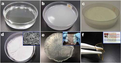
The cross-linked H2SO4-PVA gel electrolyte according to a method modified from the reference [Citation20]. shows the preparation process of the composites. In a typical procedure, 1.6 g PVA and 0.4 g PVP were first added into 24 ml deionized water and then heated at 80°C until the solution became clear. After the solution is cooled down to room temperature, the cross-linking agent (glutaraldehyde, 2.0 wt% PVA) and the catalyst (2 M H2SO4, 200 μL) were added. The resulting mixture was stirred for 30 min, allowed for degassing and then cast onto a plastic petri dish (polystyrene, dia. 90 mm × 15 mm), where it was cured at 5°C for 5 h to form PVA-PVP hydrogel. The hydrogel was freeze-dried to remove water. The obtained dry and porous PVA-PVP sheets was soaked into a 1:10 (v:v) H2SO4:H2O electrolyte solution. After the sheet was saturated with electrolyte, it was removed from the electrolyte bath and placed on a glass plate, where it was air-dried for 24 h to remove the free water on the surface. Finally, the resulting translucent and flexible PVA-H2SO4 gel electrolyte was ready for use.
Figure 1. Preparation process of cross-linked H2SO4-PVA gel electrolyte: (a) PVA solution cast on a petri dish, (b) cross-linked by glutaraldehyde, (c, d) freeze-dried, (e) soaked in H2SO4 solution and (f) formation of a freestanding gel after air drying
Material characterization
Morphology and microstructures of the composites were examined by using field emission scanning electron microscopy (FESEM, JEOL, JSM-7600 F, operated at 5 kV). Crystallographic structures of the composites were characterized by using XRD (Shimazu, XRD-6000) equipped with Cu Kα radiation (λ = 0.15406 nm) and operated at 40 kV and 30 mA. Thermal properties of the Chinese ink and the component content of the prepared composites were studied by using thermogravimetric analyzer (TGA, TA Instruments, Model Q500). The samples were loaded on a platinum pan, heated from room temperature to 600°C at a ramping rate of 10°C∙min−1 in N2/air atmosphere.
The sheet resistance of the composite sheets was measured by using the four-probe method, with an automatic-mapping four-point-probe system (Materials Development Corporation, Model CMT-SR2000N) at room temperature. The tested samples were placed onto a glass slide as the probes may penetrate the sheets and give false results. For each sample, nine even-distributed points were tested to get an average value.
Electrochemical measurement
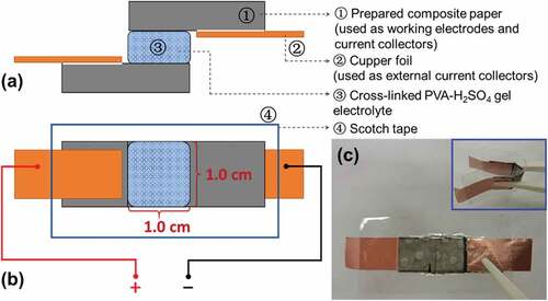
The VGCNF-ink/paper composites were also directly used as the electrodes and current collectors to assemble symmetric EDLCs. The configuration of the EDLC is schematized in . The working area (i.e. the overlapping area) of the working electrodes was 1.0 cm2. A piece of cross-linked PVA-H2SO4 gel was used as an electrolyte and a separator. The EDLC was simply wrapped in scotch tape to seclude it from the air and moisture. Meanwhile, two pieces of copper foil were used as the external current collectors.
Figure 2. Configuration of the EDLC with VGCNF-ink/paper composite sheets as working electrodes and a piece of cross-linked PVA-H2SO4 gel as electrolyte and separator: (a) side view, (b) top view and (c) digital images of the assembled EDLC
The electrochemical performance of the solid-state symmetric EDLCs was evaluated by cyclic voltammetry (CV), galvanostatic charge-discharge (GCD) and electrochemical impedance spectroscopy (EIS) on an electrochemical workstation (BioLogic, VSP potentiostat). The CV tests were conducted within an operating voltage window of 0 to 0.9 V at scanning rates of 25, 50, 100, and 200 mV s−1. The GCD was carried out in a potential window of 0 to 0.9 V at current densities of 0.5, 1.0, 2.5, 5.0, and 10 mA cm−2. The specific capacitance was calculated from GCD by the following equation:
where I is the applied current, Δt is the discharging time, ΔV is the operating voltage window excluding IR drop and S is the area of one electrode (i.e. 1.0 cm2). The EIS was done in an open-circuit potential over a frequency range from 100 kHz to 10 mHz, with an AC amplitude of 5 mV. The obtained data were fitted into equivalent circuits using the built-in function of the testing software. For cycling stability test, the electrode was charged and discharged at a current density of 5 mA cm−2 for 10,000 cycles.
Electrodeposited MnO2/VGCNF-ink/paper
The electrochemical performance of electrodeposited MnO2 on the VGCNF-ink/paper was evaluated in terms of CV, GCD, and EIS, with an electrochemical workstation (BioLogic, VSP). These tests were carried out with a three-electrode cell, which consisted of a platinum counter electrode, a saturated calomel electrode (SCE) reference electrode, and 1.0 M Na2SO4 as the electrolyte. The CV tests were conducted within an operating voltage window of −0.2 to 0.9 V (vs. SCE) at varied scanning rates. The GCD was carried out in a potential window of −0.2 to 0.9 V (vs. SCE) at different current densities. The specific capacitance was calculated from GCD using the following equation:
EIS was done in an open-circuit potential over a frequency range from 100 kHz to 10 mHz, with an AC amplitude of 5 mV. The obtained data were fitted into equivalent circuits by the built-in function in the testing software. For the cycling stability test, the electrode was charged and discharged at a current density of 5 mA cm−2 for 2000 cycles.
Results and discussion
Characteristics of the Chinese ink
Liquid Chinese ink is an intimate mixture of carbon particles, glue, miscellaneous additives, and water. In essential, Chinese ink is a kind of colloidal suspension, composed of water as the continuous phase and the surface-modified carbon nanoparticles as the dispersed phase. The carbon used in traditional Chinese ink is either soot or lampblack, which are, respectively, the products of incomplete combustion of wood (especially pinewood) and oil lamp [Citation21–24]. In some modern Chinese inks, soot, and lampblack are replaced with commercial carbon black, which is produced under well-controlled conditions and thus has smaller particle sizes, a narrower size distribution, and fewer impurities than soot and lampblack. The glue is used as the surfactant and stabilizer for modifying the surface chemistry of carbon black particles and stabilizing them in the aqueous solution [Citation25]. Animal glue (such as hide glue and egg white) and/or plant gum (such as Arabic gum and starch) are widely used in traditional Chinese ink, while the synthetic resin is commonly used in the modern Chinese ink as it can disperse and stabilize carbon black in a more efficient way. Besides glue, other additives, normally perfumes, and herb extracts may also be added to improve the physical properties of Chinese ink, such as odor, tint, and appearance.
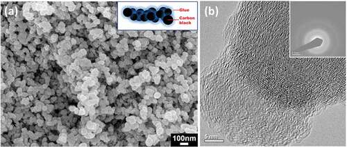
In this work, the selected Chinese ink used commercial carbon black as the black pigment, which was stabilized by some synthetic resins. shows the microstructure of the included carbon black. Strictly speaking, the basic unit of carbon black is an aciniform-shaped cluster composed of several individual particles (or called primary particles), rather than the individual particles as seen in the SEM image [Citation26]. The particle sizes of these constituent primary particles ranges from 50 to 100 nm, as estimated from the SEM image. From the TEM image (), it can be seen that the constituent primary particles are actually composed of numerous imperfect graphite layers oriented around the center. The SAED pattern reveals the amorphous character of carbon black. The rings numbered as 1, 2, and 3 correspond to graphitic (002), (100), and (110) planes, respectively [Citation27,Citation28]. The graphite layers endow carbon black with quasi-crystal features that can be detected by XRD or Raman spectroscopy [Citation29,Citation30]. As determined by the TGA, the content of water and carbon black in this Chinese was 92.3% and 5.2%, respectively, while the synthetic resin and miscellaneous additives only made up 2.5%.
Figure 3. (a) SEM image of dried Chinese ink (carbon black) with the inset to show the schematic diagram of carbon black particles in the Chinese ink. (b) TEM image and SAED (the inset) of the carbon black in the Chinese ink
Morphology of the VGCNF-ink/paper composites
displays typical appearance of the VGCNF-ink/paper composites. The uniform color and flat surface indicate the uniform dispersion of VGCNF and carbon black particles, which were firmly bonded to the filter paper surface by the glue from Chinese ink. By contrast, in the sample prepared without Chinese ink (), the distribution of VGCNFs became uneven; the fibers tended to pile up around the holes in the Büchner funnel owing to strong suction force there. When dried, these VGCNFs would easily drop out from the filter paper owing to the absence of binders. It is noteworthy that carbon black particles could easily penetrate the filter paper. When only Chinese ink was filtered, the vast majority of carbon black particles would directly pass through the pores in filter paper (Figure S1). However, when VGCNFs were combined, they formed a mesh that could trap most of the carbon black particles.
Figure 4. Digital images of the VGCNF-ink/paper (a) and the VGCNF/paper composites (b). SEM images of the raw filter paper (c) and the VGCNF-ink/paper composite (d–f)
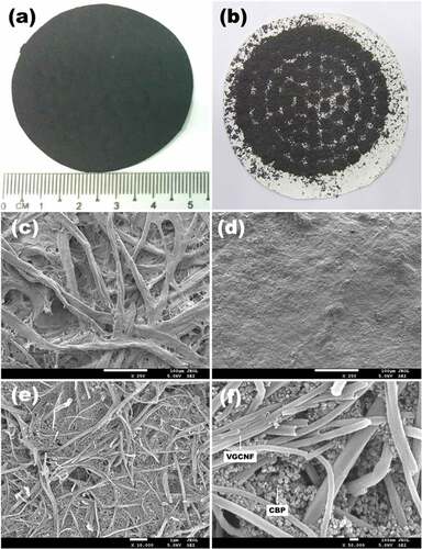
The microstructures (SEM images) of the paper-based composites are demonstrated in . As observed in , the filter paper surface was blanked with VGCNFs and carbon black particles after filtration-deposition. The high-magnification images () reveal the effective disentanglement of VGCNFs by horizontal ball milling with the aid of Chinese ink. Carbon black particles acted as spacers segregating the fibers.
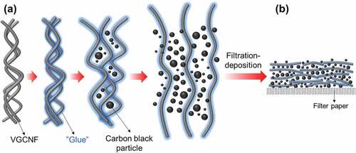
The role of Chinese ink on dispersing VGCNFs can be illustrated by . For one thing, as a surfactant and a stabilizer, the glue from Chinese ink could exert the same influence on VGCNFs as on carbon black particles. When Chinese ink was mixed with VGCNFs, the free glue attaches to the surface of VGCNFs, inducing electrostatic or steric repulsion that counterbalances the Van der Waals’s force between adjacent fibers [Citation31,Citation32]. During the milling process, the local shear force delivered by running balls could separate the entangled VGCNFs and more surfaces for glue adhesion, whilst carbon black particles filled the space among the fibers. As ball milling proceeded, the VGCNFs were gradually segregated from one another and dispersed in the suspension. Further, the presence of carbon black particles prevented the segregated VGCNFs from secondary agglomeration during filtration. Accordingly, when transferred onto filter paper via filtration, the VGCNFs could be well distributed.
Figure 5. Schematic diagram illustrating the disentanglement process of VGCNFs (a) and the deposition of VGCNFs and carbon black particles on filter paper (b)
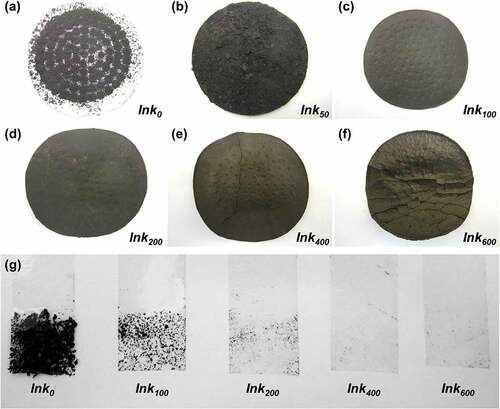
The additional amount of Chinese ink largely affected the appearance and the structural strength of VGCNF-ink/paper composites. Photographs of the composites prepared with different contents of Chinese ink are shown in . A rough surface accompanied by severe agglomeration of fibers was observed in the composites with insufficient Chinese ink (Ink0 and Ink50). The composite surface became smoother with an increased amount of Chinese ink (Ink100 and Ink200). No obvious cracks were seen even when the composites were bent. The good flexibility should be attributed to a robust network in the deposition layer, which was formed by dispersed VGCNFs and bound by the glue from Chinese in, as seen in . The improved bond between VGCNFs and Chinese ink was also confirmed by the tape test. As seen in , the amount of VGNCFs peeled off significantly decreased with increasing loading content of Chinese ink. However, excessive Chinese ink was counterproductive as it unfavorably thickened the deposition layer and caused cracks after drying (Ink400 and Ink600). This is because the connection between VGCNFs was cut off by undue carbon black particles (as seen in Figure S2). Hence, the composites made with 200 mg·cm−2 Chinese ink was selected for subsequent electrochemical experiments.
Figure 6. (a–f) Appearance of the VGCNF-ink/paper composites containing 2.5 mg·cm−2 VGCNFs and Chinese ink with varied loading contents: (a) 0, (b) 50, (c) 100, (d) 200, (e) 400 and (f) 600 mg·cm−2. (g) Tape test of the VGCNF-ink/paper composites containing 2.5 mg·cm−2 of VGCNFs and Chinese ink with varied loading contents
Electrical conductivity of the VGCNF-ink/paper composites
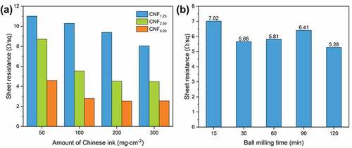
The electrical conductivity of the VGCNF-ink/paper composites was reflected by sheet resistance, which was measured by the four-point probe method. displays sheet resistances of the VGCNF-ink/paper composites with different compositions. As expected, the sheet resistance declined with increasing content of VGCNFs. With the same loading content of VGCNFs, composites with more Chinese ink showed lower sheet resistance (i.e. higher electrical conductivity.) The contribution of Chinese ink to the improved thermal conductivity can be summarized into two aspects: one is that the carbon black particles are filled in the gap between VGCNFs, reducing the voids in the composite; and the other is that the glue from Chinese ink bonds the VGCNFs and carbon black particles together, consolidating the conduction network. Additionally, a trend was observed in which the sheet resistance of composites tended to decrease with increasing ball milling time (). As ball milling was prolonged, more VGCNFs could be disentangled, which would eventually contribute to a more efficient conduction network. However, excessive ball milling is counter-productive because it will chop the fibers and the resulting short fiber fragments are less efficient in constructing a conduction network.
Figure 7. Sheet resistances of the VGCNF-ink/paper with (a) loading content of VGCNFs and ink and (b) ball milling time
Electrochemical performance of the VGCNF-ink/paper composites
Considering the high electrical conductivity and good flexibility of the paper-based composites, we applied the prepared VGCNF-ink/paper composites as electrodes to fabricate solid-state symmetric EDLCs. A piece of cross-linked PVA-H2SO4 gel was used as the electrolyte and the separator. This cross-linked PVA-H2SO4 gel was an ideal electrolyte for a paper-based supercapacitor because it reserved a considerable amount of electrolyte ions while preventing the direct contact between two electrodes [Citation20]. The appearance of the fabricated EDLC is shown in .
The electrochemical behavior of the prepared symmetric EDLC was studied using CV and GCD. shows CV curves at a constant scanning rate of 200 mV·s−1 within different potential windows. When the potential window was not higher than 1.2 V, the CV curves showed a quasi-rectangle shape and nearly symmetric current response on the reverse sweep, suggesting fast capacitive response and high reversibility. However, when the potential window exceeded 1.2 V, the CV curve distorted at high potentials, due to the electrode polarization and possible irreversible reaction [Citation33]. Similar electrochemical behavior could also be observed in GCD. As displayed in the inset in , when the potential window was not more than 1.2 V, both charge and discharge curves showed a linear profile, which indicated good capacitive characteristics [Citation34]. However, when the upper potential limit exceeded 1.2 V, the charge curve distorts at high potential due to electrode polarization. Based on the GCD, the Coulombic efficiency was calculated by the following equation:
Figure 8. Electrochemical performance of the EDLCs with VGCNF (2.5 mg·cm−2)-ink (200 mg·cm−2)/paper electrodes: (a) CV curves at 200 mV·s−1 within different potential windows, (b) Coulombic efficiency against different potential windows, (c) CV curves at different scanning rate within a potential window of 0 to 0.9 V, (d) GCD curves at different current densities within a potential window of 0 to 0.9 V and (e) capacitance retention rate at a current density of 5.0 mA·cm−2 for 10,000 cycles. (f) Photograph of three EDLCs in series to light up a LED
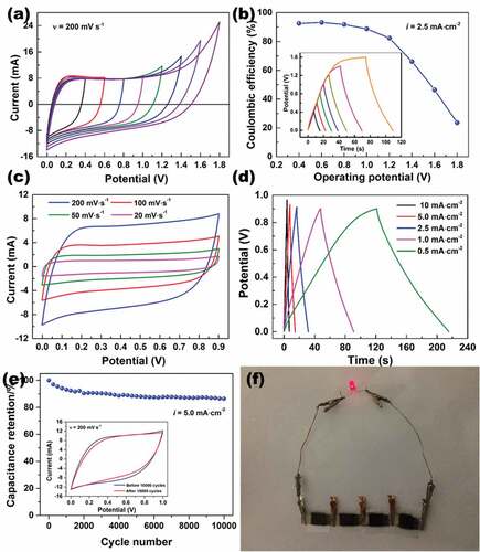
where, q is the number of involved charges during charging (or discharging), Δt is the time of charging (or discharging), and the subscripts ‘d’ and ‘c’ denote ‘discharge’ and ‘charge,’ respectively. As seen in , the Coulombic efficiency declined with increasing potential windows. An enlarged potential window is advantageous to high specific capacitance, but in this case, it also leads to the decay in Coulombic efficiency. Thus, a trade-off is needed to be made between specific capacitance and Coulombic efficiency by adjusting the potential windows. Here, the potential window was fixed at 0–0.9 V. In this potential window, the EDLC exhibited ideal capacitive performance, as evidenced by the quasi-rectangle profile of the CV curves at varying scanning rates as well as the linear and symmetric GCD curves at varying current densities (). After being charged and discharged at 5.0 mA cm2 for 10,000 cycles, the EDLC retained 86.4% of the initial capacitance and showed no substantial change in the CV curve profile, which indicated decent cycling stability. As a proof of concept, a power supply prototype was fabricated by connecting four identical EDLCs in series, which could light up a 3 V LED ().
A systematic study was conducted to investigate how Chinese ink affected the electrochemical performance of paper-based composites. Likewise, the paper-based composites with the loading content of Chinese ink ranging from 50 to 300 mg·cm−2 were used to fabricate symmetric EDLCs. displays the CV curves of these symmetric EDLCs at a scanning rate of 50 mV·s−1. All these CV curves showed a quasi-rectangle profile, suggesting a good capacitive performance. The enclosed area of CV curves increased with increasing loading density of Chinese, corresponding to improved specific capacitance. It is noteworthy that the composite made with only Chinese ink showed an enclosed area of almost zero. This is because, in the absence of VGCNFs, most of the carbon black particles would directly pass through the filter paper, while the rest adsorbed by the filter paper failed to form an effective conduction network that was required for a fast capacitive response.
Figure 9. Electrochemical performances of the EDLCs with VGCNF (2.5 mg·cm−2)-ink/paper electrodes containing different loading densities of Chinese ink: (a) CV curves at 50 mV·s−1, (b) specific capacitance at different current densities, (c) equivalent series resistance, (d) Nyquist plots, (e) Bode plots and (f) cycling stability measured at a current density of 5.0 mA·cm−2
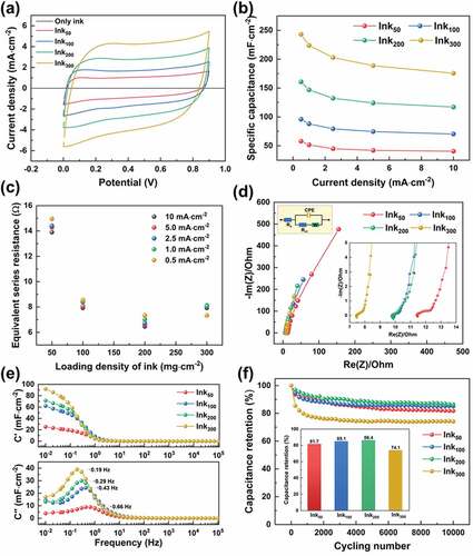
depicts the specific capacitance and the rate capability of these EDLCs over different current densities. All these EDLCs showed similar rate capability, retaining about 72% of the specific capacitance as the current density was raised from 0.5 A·cm−2 to 10 A·cm−2. Moreover, the specific capacitance showed an apparently positive correlation with the loading density of Chinese ink. The enhancement in specific capacitance by Chinese ink can be attributed to the improved electrical conductivity as well as the additional contribution to capacitance made by carbon black. First, as aforementioned, Chinese ink facilitated the dispersion of pristine VGCNFs and provided the necessary binder that ensures a robust conducting network. Thus, higher thermal conductivity (i.e. lower sheet resistance) was achieved on the sample with more Chinese ink. Evidence for this could also be found from the equivalent series resistance (ESR) of these EDLCs (), which was estimated from the IR drop in GCD curves. For instance, the ESR was reduced by nearly half when the loading content of Chinese ink was increased from 50 mg cm−2 to 200 mg cm−2. The improved dispersion of VGCNFs may also result in more exposed surfaces that were accessible to electrolytes. Second, the well-dispersed VGCNFs interwove to form a mesh with narrow pores that could retain carbon black particles during filtration. The retained carbon black particles could also contribute additional capacitance owing to their specific surface area.
The capacitive behavior of these EDLCs was further studied by EIS. In the Nyquist plots (), less deviation from the imaginary axis observed in the sample with a large loading content of Chinese ink was indicative of better capacitive performance. The observation is in accordance with previous discussions. The Bode plots in show the evolution of the real part (C’) and imaginary part of capacitance (C”) over frequency, which provide insight into the rate capability of these EDLCs. The EDLC can be simplified as a combination of a resistor and a capacitor whose impedance is dependent on the angular frequency ω. The capacitance of the EDLC can be expressed in the form of as complex as:
The real part (C’) and the imaginary part (C”) of the capacitance are expressed as:
where Z’(ω) and Z”(ω) are the real part and the imaginary part of the impedance Z(ω) [Citation35]. The real part of the capacitance (C’) is effective capacitance delivered by the EDLC, while the imaginary part of the capacitance (C”) corresponds to the energy dissipation by the IR drop and irreversible Faradaic reaction that can lead to a hysteresis in the electrochemical process [Citation36–38]. The real part of the capacitance (C’) is highly dependent on the frequency, increasing sharply as the frequency goes below 1 Hz. At a high frequency, the majority of electrolyte ions can only approach the surface of electrode materials, while at low frequencies, electrolyte ions can permeate into the deep pores in and contribute to a high capacitance [Citation35].
The frequency at which the C” peaks is defined as the characteristic frequency (f0); it marks the point where the resistive and capacitive impedance is equal [Citation39]. The reciprocal of the characteristic frequency f0 is referred as the time constant τ0 = 1/f0, representing the minimum time needed to discharge all the energy from the device with an efficiency of >50% [Citation35]. As seen in , the characteristic frequency dropped from 0.66 to 0.43, 0.29, and 0.19 Hz as the loading density of Chinese ink in the electrodes increased from 50 to 100, 200 and 300 mg cm−2, corresponding to the increase in the time constant from 1.51 to 2.33, 3.45, and 5.26 s, respectively. According to the Equation τ = RC, the observed positive correlation between the time constant and the loading density of Chinese ink in the electrode can be attributed to the enlarged capacitance by increasing the additional amount of Chinese ink.
To evaluate the cycling stability, these devices were subjected to continuous charge-discharging at a constant current of 5 mA for 10,000 cycles. As revealed by , these EDCLs (especially the sample Ink300) degraded quickly in the first 1400 cycles but stabilized afterward. The capacitance retention rates after 10,000 cycles for Ink50, Ink100, Ink200 and Ink300 were 81.7%, 85.1%, 86.4%, and 74.1%, respectively. Hence, although composites made with more Chinese ink tended to have better cycling stability (i.e. Ink50 < Ink100 < Ink200), excessive Chinese ink (Ink300) could lead to a counterproductive result. The reason for the worse capacitance retention rate of the sample Ink300 may lie in the additives used in Chinese ink, i.e. synthetic resins, which functions as surfactants/stabilizers enhancing the dispersion of carbon black particles. The downside of the additives is that they are insulating and can erect barriers to ion diffusion. More importantly, when the EDLCs are subjected to current, the presence of these additives may induce some irreversible side reaction that accounts for the loss in capacitance. In fact, most of the capacitance loss occurred in the first 1000 cycles, beyond which these four EDLCs showed no significant difference in capacitance loss rate. More study work is needed to pinpoint the root cause.
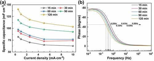
In addition to the loading content of Chinese ink, the ball milling also significantly affected the capacitance of the prepared EDLCs. As shown in , the areal-specific capacitance of the EDLCs had a positive correlation with the ball milling time. The improved capacitance is attributed to the better dispersion of VGCNFs by Chinese ink under prolonged ball milling, which can create more accessible pores and surface for ion adsorption. Likewise, as revealed by the Bode phase plots (), as the ball milling time was increased from 15 min to 120 min, the characteristic frequency at the phase of −45° decreased from 0.58 Hz to 0.25 Hz, while the phase at low frequencies deviated more from of −90°‒the ideal capacitor. All these findings suggest that prolonged ball milling can help boost the capacitance of the paper-based composites.
Figure 10. (a) Specific capacitance and (b) characteristic frequency of the EDLCs with VGCNF (2.5 mg·cm−2)-ink (200 mg·cm−2)/paper electrodes made with different times of ball milling
VGCNF-ink/paper as a substrate for the electrodeposition of metal oxides
The high electrical conductivity and the porous structure make the VGCNF-ink/paper composites promising as the substrates for the electrochemical deposition (or electrodeposition, ED) of metal oxides. Compared to nickel foam or carbon cloth, these paper-based substrates can offer more effective surfaces for the electrodeposition. To prove this, we used the composite paper made with 2.0 mg cm−2 of VGCNFs and 100 mg cm−2 of Chinese ink as the substrate to electrodeposit MnO2.
Commonly, the techniques used for electrodepositing MnO2 include (1) potentiostatic ED (PED), achieved by applying a constant voltage on the working electrode [Citation40–42]; (2) galvanostatic ED (GED), achieved by applying a constant current on the working electrode [Citation43]; and (3) potentiodynamic-ED (i.e. CV), achieved by applying a constant sweeping rate on the working electrode within a certain potential window [Citation44–49]. These ED techniques can be divided into anodic electrodeposition and cathodic electrodeposition. Here, applied the VGCNF-ink/paper was used as the anode to electrodeposit MnO2 from Mn(CH3COO)2 through PED and GED, which involved the directional migration of Mn2+ from the electrolyte to the anode where the Mn2+ is electrochemically oxidized into MnO2 according to the following reaction [Citation50]:
Current and potential of the working electrode during PED and GED are depicted in , respectively. In the case of PED, the current of the working electrode declined sharply in the first 80 s and leveled off afterward. The derivative curve gave a better insight into the change in the current response, which became stable after 80 s. Likewise, in the case of GED, the potential of the working electrode rose quickly in the first 150 s and increases steadily afterward. The high electrical conductivity of the substrate guaranteed efficient electron transportation. Thus, MnO2 could be rapidly produced and cover the substrate once current was applied. However, due to the low electrical conductivity, the deposited MnO2 dramatically raised the resistance of the working electrode, which reduced the electron transfer efficiency and slowed down the formation of MnO2.
Figure 11. (a) Current response during the potentiostatic electrodeposition of MnO2 at 1.0 V vs. SCE. (b) Potential response during the galvanostatic electrodeposition of MnO2 at 5 mA. (c, d) XRD patterns of the electrodeposited MnO2/VGCNF-ink/paper and pure starting materials. (e) Mn 2p and (f) O 1s XPS spectra of electrodeposited MnO2
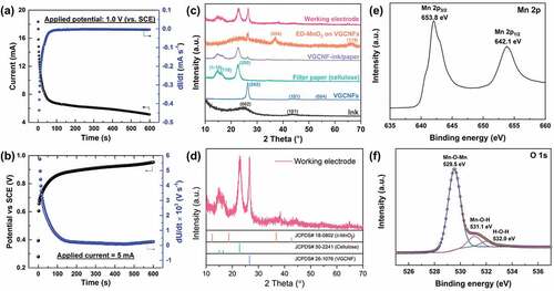
XPS and XRD were applied to confirm the formation of MnO2 and to determine the oxidation states of manganese. The XPS characterization results shown in ) suggest the manganese element is presented in the chemical state of Mn4+. The peaks at 653.8 eV and 642.1 eV in the Mn 2p spectrum are assigned to the Mn 2p3/2 and Mn 2p1/2 of Mn4+, respectively. The spin energy separation between these two peaks is 11.7 eV. These results are in accordance with the previous reports [Citation19,Citation49,Citation51]. The O 1s spectrum consists three peaks centered at 529.5 eV, 531.1 eV and 532.0 eV, which are attributed to Mn-O-Mn, Mn-O-H, and H-O-H, respectively [Citation18]. The XPS results indicate the material resulting from electrodeposition could be MnO2·nH2O [Citation19]. XRD analysis further verified the formation of MnO2 and the results are shown in . The electrodeposited MnO2 was indexed to δ-MnO2 (JCPDS No. 18–0802) with a low crystallinity [Citation6,Citation52–54]. compares the morphologies of the pristine substrate and the electrodeposited MnO2 formed at different times. As the electrodeposition proceeded, the MnO2 crystals grew and evolved into well-defined flower-shaped nanostructures, blanketing the substrate.
Figure 12. Electrochemical performance of the electrodeposited MnO2/VGCNF-ink/paper tested in the configuration a three-electrode cell: (a) CV curves at varied scanning rates, (b) GCD curves at different current densities, and (c) cycling stability of (5 mA_5 min)-GED MnO2/VGCNF-ink/paper. Comparison in (d) specific capacitance, (e) Nyquist plots, (f) characteristic frequency and (g, h) Bode plots of the pristine VGCNF-ink/paper and the electrodeposited MnO2/VGCNF-ink/paper obtained in different ED conditions
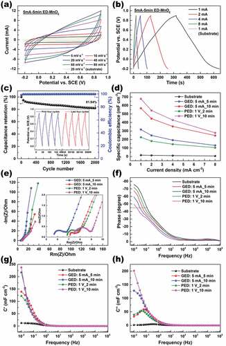
The electrochemical performance of electrodeposited-MnO2/VGCNF-ink/paper quaternary composites was evaluated by CV, GCD, and EIS in a three-electrode system, and the quaternary composite. Taking the sample prepared by GED (5 mA_5 min) as an example, typical CV and GCD curves are displayed in ). The quasi-rectangle profile of CV curves and linear charge/discharge curves confirmed the good capacitive behavior [Citation49,Citation55]. The small IR drop suggested good electrical conductivity of the composite electrode, which resulted from the strong bonding between the substrate and electrodeposited MnO2. This sample shoved a specific capacitance of 317 mF·cm−2 at the current of 1 mA, about 20 times higher than 16 mF·cm−2 of the substrate. In addition, this sample retained 81.94% of the initial capacitance after being continuously charged and discharged at a current of 2 mA for 2000 cycles.
The samples prepared by GED and PED with different parameters showed similar curves of CV and GCD, but different calculated capacitance. The areal-specific capacitance of the working electrode was proportional to the amount of electrodeposited MnO2, which was mainly determined by the applied current (or potential) and electrodeposition time, regardless of whether the ED was carried out in a galvanostatic mode or in a potentiostatic mode. compares the specific capacitance of these quaternary composite electrodes, in which PED (1 V_2 min) < GED (5 mA_5 min) < GED (5 mA_10 min) < PED (1 V_10 min).
The EIS analysis was applied to probe into the impedance behavior of these composites. Basically, a Nyquist plot for a supercapacitor can be resolved into three regions. In the high-frequency region, the intercept of the curve with the real Z-axis represents the ESR of the electrode. In the high-to-medium frequency region, usually a semicircle is observed, associated with the charge transfer resistance. In the medium-to-low frequency region, a linear one with a finite slope is observed, representing the diffusion resistance of electrolyte ions in the pores of the electrode [Citation46,Citation48]. Thus, it can be inferred from the Nyquist plots () that the electrode with a thicker electrodeposition layer showed larger ESR, charge transfer resistance, and diffusion resistance. Additionally, in the Bode plots (), the electrode with a thicker electrodeposition layer showed larger deviation from −90° at 0.01 Hz – an ideal capacitor, as well as a smaller characteristic frequency at −45º, i.e. an enlarged time constant. These observations lead to the conclusion that prolonged electrodeposition can contribute to higher specific capacitance, but meanwhile it increases the internal resistance. Also, noteworthy is that undue electrodeposition will be detrimental to the electrochemical performance of the quaternary composites [Citation56]. This is because the electron/mass transfer in a thick layer of MnO2 is sluggish. Furthermore, the bond between the substrate and MnO2 fails to support excess MnO2, which will drop off during testing, causing remarkable degradation in the capacitance and cycling stability.
Conclusions
To sum up, we have demonstrated in this work that commercial Chinese ink was effective in dispersing pristine VGCNFs in aqueous suspension via horizontal ball milling. The role played by Chinese ink was twofold. Firstly, as surfactants/stabilizers, the glue from Chinese ink could exert the same influence on VGCNFs as on carbon black. Second, carbon black particles functioned as spacers, separating VGCNFs and preventing VGCNFs from secondary agglomeration during filtration. On this basis, the VGCNF-ink suspension was filter-deposited on filter paper to fabricate a flexible and conductive VGCNF-ink/paper composite, whose sheet resistance decreased with increasing content of Chinese ink. With merely 2.5 mg·cm−2 of VGCNFs, the sheet resistance could be reduced to 4.5 Ω·sq−1.
The strong flexibility and high electrical conductivity enabled the VGCNF-ink/paper ternary composites to be suitable electrode materials for supercapacitors. As a proof of concept, solid-state symmetric EDLCs were fabricated with the composite as electrodes and cross-linked H2SO4-PVA gel as an electrolyte. The specific capacitance of the EDLCs had a positive correlation with the content of Chinese ink. The sample fabricated with 2.5 mg·cm−2 of VGCNFs and 200 mg cm−2 of Chinese ink showed an areal-specific capacitance of 224 mF·cm−2 at a current density of 1 mA·cm−2, and retained 86.4% of the initial capacitance after 10,000 charge-discharge cycles.
Furthermore, the good electrical conductivity and porous nature made the VGCNF-ink/paper ternary composites ideal substrates for the electrodeposition of transition metal oxides. As a proof of concept, the paper-based composite was directly used as a substrate to conduct the electrodeposition of MnO2. Due to the good electrical conductivity, the electrodeposition of MnO2 could be accomplished in several minutes. The deposited MnO2 dramatically boosted the specific capacitance of the working electrode. The sample prepared with 5-mA galvanostatic electrodeposition for 5 min showed a specific capacitance of 317 mF·cm−2 at the current of 1 mA, about 20 times higher than that of the neat substrate.
This work has well demonstrated the merit of commercial Chinese ink as a starting material for scientific research and proved the feasibility of employing Chinese ink-involved paper-based composites as electrode materials for supercapacitors. Due to the lightweight and easy disposal, paper-based supercapacitors hold promise for large-scale application. The methods developed are facile, safe, and low-cost. Hence, they can be extended to process other one-dimensional materials.
Supplemental Material
Download MS Word (2.5 MB)Acknowledgments
This work was supported by the National Natural Science Foundation of China (51762023 and 51962013), Natural Science Foundation of Jiangxi Province (20192ACB20018 and 20202BABL204020), Key R&D Program of Jiangxi Province (20192ACB80007, 20201BBE51011, 20192ACB80004 and jxsq2019201036), the projects of Shenzhen Technology University (SZTU) Start-up Grant (2018), Natural Science Foundation of Top Talent Project of SZTU (Grant No. 2019010801002), General Projects of Shenzhen Stable Development (SZWD2021003) and Key Projects of Provincial-Regional Joint Fund (2020B1515120002).
Disclosure statement
No potential conflict of interest was reported by the author(s).
Supplementary material
Supplemental data for this article can be accessed here
References
- Liu T, Zhang F, Song Y, et al. Revitalizing carbon supercapacitor electrodes with hierarchical porous structures [J]. ?J Mater Chem A. 2017;5(34):17705–17733.
- Borenstein A, Hanna O, Attias R, et al. Carbon-based composite materials for supercapacitor electrodes: a review [J]. ?J Mater Chem A. 2017;5(25):12653–12672.
- Acharya J, Balasubramaniam G, Raj S, et al. Facile one pot sonochemical synthesis of CoFe2O4/MWCNTs hybrids with well-dispersed MWCNTs for asymmetric hybrid supercapacitor applications [J]. Int J Hydrogen Energy. 2020;45(4):3073–3085.
- Ojha GP, Gautam J, Muthurasu A, et al. In-situ fabrication of manganese oxide nanorods decorated manganese oxide nanosheets as an efficient and durable catalyst for oxygen reduction reaction [J]. Colloids Surf A Physicochem Eng Asp. 2019;568:311–318.
- Acharya J, Ojha GP, Kim B-S, et al. Modish Designation of Hollow-Tubular rGO–NiMoO4 @Ni–Co–S Hybrid Core–shell Electrodes with Multichannel Superconductive Pathways for High-Performance Asymmetric Supercapacitors. ACS Appl Mater Interfaces. 2021;13(15):17487–17500.
- Ojha GP, Muthurasu A, Dahal B, et al. Oleylamine-assisted synthesis of manganese oxide nanostructures for high-performance asymmetric supercapacitos [J]. J Electroanal Chem. 2019;837:254–265.
- Jiang H, Lee PS, Li C. 3D carbon based nanostructures for advanced supercapacitors [J]. Energy Environ. Sci 2013;6(1):41–53.
- Xiao Z, Sun X, Xiuying L, et al. Phase transformation of GeO2 glass to nanocrystals under ambient conditions [J]. Nano Lett. 2018;18(5):3290–3296.
- Bryan AM, Santino LM, Lu Y, et al. Conducting polymers for pseudocapacitive energy storage [J]. Chem Mater. 2016;28(17):5989–5998.
- Sahalianov I, Singh SK, Tybrandt K, et al. The intrinsic volumetric capacitance of conducting polymers: pseudo-capacitors or double-layer supercapacitors? [J]. RSC Adv. 2019;9(72):42498–42508.
- Veerakumar P, Sangili A, Manavalan S, et al. Research Progress on Porous Carbon Supported Metal/Metal Oxide Nanomaterials for Supercapacitor Electrode Applications [J]. Ind Eng Chem Res. 2020;59(14):6347–6374.
- Mohammed H Al-Saleh, Uttandaraman Sundararaj. A review of vapor grown carbon nanofiber/polymer conductive composites [J]. Carbon. 2009. 47(1):2–22
- Hirsch A. Functionalization of Single-Walled Carbon Nanotubes. Angew Chem. 2002;41(11):1853–1859.
- Ma P-C, Siddiqui Naveed A, Marom G, et al. Dispersion and functionalization of carbon nanotubes for polymer-based nanocomposites: a review [J]. Compos Part A Appl Sci Manuf. 2010;41(10):1345–1367.
- Lingjie M, Chuanlong F, Qinghua L. Advanced technology for functionalization of carbon nanotubes [J]. Progress in Natural Science, 2009;19(7):801–810.
- Rong W, Chao C, Xiuchun YANG. New electrode materials for supercapacitors [J]. Journal of Ceramics, 2018; 39(6):649–660 (in Chinese)
- Xiao Z, Shijin Y, Yueming L, et al. Materials development and potential applications of transparent ceramics: a review [J]. Mater Sci Eng R Rep. 2020;139:100518.
- Dai X, Zhang M, Li J, et al. Effects of electrodeposition time on a manganese dioxide supercapacitor [J]. RSC Adv. 2020;10(27):15860–15869.
- Zhang M, Chen Y, Yang D, et al. High performance MnO2 supercapacitor material prepared by modified electrodeposition method with different electrodeposition voltages [J]. J Energy Storage. 2020;29:101363.
- Fei H, Chongyang C, Bao H, et al. Flexible all-solid-state supercapacitors based on graphene/carbon black nanoparticle film electrodes and cross-linked poly(vinyl alcohol)–H2SO4 porous gel electrolytes. J Power Sources. 2014;266:488–495.
- Winter J. Preliminary investigations on Chinese ink in far eastern paintings [J]. Adv Chem Series. 1975;138:207–225.
- Tesner P. Soot formation during combustion [J]. Combustion, Explosion, and Shock Waves. 1979;15(2):111–120.
- Dobbins RA, Fletcher RA, Chang H-C. The evolution of soot precursor particles in a diffusion flame [J]. Combustion and flame. 1998;115(3):285–298.
- Wei S, Fang X, Cao X, et al. Characterization of the materials used in Chinese ink sticks by pyrolysis-gas chromatography–mass spectrometry [J]. J Anal Appl Pyrolysis. 2011;91(1):147–153.
- Swider JR, Hackley VA, Winter J. Characterization of Chinese ink in size and surface [J]. J CultHeritage. 2003;4(3):175–186.
- Watson Ann Y, Valberg Peter A. Carbon black and soot: two different substances [J]. AIHAJ - American Industrial Hygiene Association. 2001;62(2):218–228.
- Kumari L, Subramanyam SV. Optical properties and electrical transport in intercalated amorphous carbon [J]. Mater Res Bull. 2006;41(11):2000–2006.
- Sahu V, Shekhar S, Ahuja P, et al. Synthesis of hydrophilic carbon black; role of hydrophilicity in maintaining the hydration level and protonic conduction [J]. RSC Adv. 2013;3(12):3917–3924.
- Jawhari T, Roid A, Casado J. Raman spectroscopic characterization of some commercially available carbon black materials [J]. Carbon. 1995;33(11):1561–1565.
- Darmstadt H, Roy C, Kaliaguine. Characterization of pyrolytic carbon blacks from commercial tire pyrolysis plants [J]. Carbon. 1995;33(10):1449–1455.
- Vigolo B, Pénicaud A, Coulon C, et al. Macroscopic fibers and ribbons of oriented carbon nanotubes [J]. Science. 2000;290(5495):1331–1334.
- Yu J, Grossiord N, Koning Cor E, et al. Controlling the dispersion of multi-wall carbon nanotubes in aqueous surfactant solution [J]. Carbon. 2007;45(3):618–623.
- Xia H, Shirley MY, Yuan G, et al. A Symmetric RuO2∕RuO2 Supercapacitor Operating at 1.6 V by Using a Neutral Aqueous Electrolyte. Electrochem Solid State Lett. 2012;15(4):A60–A63.
- Liao Q, Li N, Jin S, et al. All-Solid-State Symmetric Supercapacitor Based on Co3 O 4 Nanoparticles on Vertically Aligned Graphene. ACS Nano. 2015;9(5):5310–5317.
- Biswal M, Banerjee A, Deo M, et al. From dead leaves to high energy density supercapacitors [J]. Energy Environ Sci. 2013;6(4):1249–1259.
- Taberna P, Simon P, Fauvarque JF. Electrochemical characteristics and impedance spectroscopy studies of carbon-carbon supercapacitors [J]. J Electrochem Soc. 2003;150(3):A292–A300.
- Bello A, Fashedemi OO, Barzegar F, et al. Microwave synthesis: characterization and electrochemical properties of amorphous activated carbon-MnO2 nanocomposite electrodes [J]. J Alloys Compd. 2016;681:293–300.
- Zhi M, Manivannan A, Meng F, et al. Highly conductive electrospun carbon nanofiber/MnO2 coaxial nano-cables for high energy and power density supercapacitors [J]. J Power Sources. 2012;208:345–353.
- Yuxi X, Zhaoyang L, Xing Z, et al. Holey graphene frameworks for highly efficient capacitive energy storage [J]. Nature Communications. 2014. 5: 4554.
- Liu F-J. Electrodeposition of manganese dioxide in three-dimensional poly(3,4-ethylenedioxythiophene)–poly(styrene sulfonic acid)–polyaniline for supercapacitor [J]. J Power Sources. 2008;182(1):383–388.
- Gao H, Xiao F, Ching CB, et al. High-Performance Asymmetric Supercapacitor Based on Graphene Hydrogel and Nanostructured MnO 2 . ACS Appl Mater Interfaces. 2012;4(5):2801–2810.
- Zhou H, Zou X, Zhang Y. Fabrication of TiO2@MnO2 nanotube arrays by pulsed electrodeposition and their application for high-performance supercapacitors [J]. Electrochim Acta. 2016;192:259–267.
- Nagarajan N, Humadi H, Zhitomirsky I. Cathodic electrodeposition of MnOx films for electrochemical supercapacitors [J]. Electrochim Acta. 2006;51(15):3039–3045.
- Yang J, Lian L, Ruan H, et al. Nanostructured porous MnO2 on Ni foam substrate with a high mass loading via a CV electrodeposition route for supercapacitor application [J]. Electrochim Acta. 2014;136:189–194.
- Cross A, Morel A, Cormie A, et al. Enhanced manganese dioxide supercapacitor electrodes produced by electrodeposition [J]. J Power Sources. 2011;196(18):7847–7853.
- Chou S, Cheng F, Chen J. Electrodeposition synthesis and electrochemical properties of nanostructured γ-MnO2 films [J]. J Power Sources. 2006;162(1):727–734.
- Chou S-L, Wang J-Z, Chew S-Y, et al. Electrodeposition of MnO2 nanowires on carbon nanotube paper as free-standing, flexible electrode for supercapacitors [J]. Electrochem commun. 2008;10(11):1724–1727.
- Tahmasebi MH, Raeissi K, Golozar MA, et al. Tailoring the pseudocapacitive behavior of electrochemically deposited manganese-nickel oxide films [J]. Electrochim Acta. 2016;190:636–647.
- Park SK, Suh DH, Park HS. Electrochemical assembly of reduced graphene oxide/manganese dioxide nanocomposites into hierarchical sea urchin-like structures for supercapacitive electrodes [J]. J Alloys Compd. 2016;668:146–151.
- Jian-Gan W, Feiyu K, Bingqing W. Engineering of MnO2-based nanocomposites for high-performance supercapacitors [J]. Pro Mater Sci. 2015;74:51–124.
- Xuguang Y, Pan C, Yuhang G, et al. Preparation of Al3+ doped MnO2 hollow nanospheres and its application in energy storage [J]. Journal of Ceramics, 2019; 40(6):757–763 (in Chinese
- Zhang A, Gao R, Hu L, et al. Rich bulk oxygen Vacancies-Engineered MnO2 with enhanced charge transfer kinetics for supercapacitor [J]. Chem Eng J. 2021;417:129186.
- Ma L, Meng N, Zhang Y, et al. Improved electrocatalytic activity of δ-MnO2@MWCNTs by inducing the oriented growth of oxygen reduction products in Li-O2 batteries [J]. Nano Energy. 2019;58:508–516.
- Dang MN, Nguyen TH, Nguyen TV, et al. One-pot synthesis of manganese oxide/graphene composites via a plasma-enhanced electrochemical exfoliation process for supercapacitors [J]. Nanotechnology. 2020;31(34):345401.
- Choi BG, Huh YS, Hong WH, et al. Electrochemical assembly of MnO2 on ionic liquid–graphene films into a hierarchical structure for high rate capability and long cycle stability of pseudocapacitors [J]. Nanoscale. 2012;4(17):5394–5400.
- Ojha GP, Pant B, Muthurasu A, et al. Three-dimensionally assembled manganese oxide ultrathin nanowires: prospective electrode material for asymmetric supercapacitors [J]. Energy. 2019;188:116066.