
 ?Mathematical formulae have been encoded as MathML and are displayed in this HTML version using MathJax in order to improve their display. Uncheck the box to turn MathJax off. This feature requires Javascript. Click on a formula to zoom.
ABSTRACT
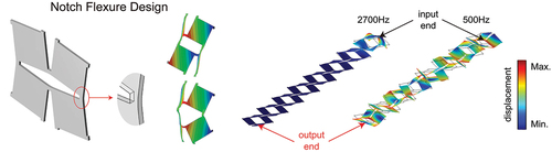
Kirigami is an art of paper cutting, which can be used in mechanical metamaterials, actuators, and energy absorption based on its deployable and load-deflection characteristics. Traditional cuts with zero width produce undesirable plastic deformation or even tear fracture due to stress concentration in stretching. This study proposes to enlarge the cut width into a notch flexure, which is applied to an orthogonality-cutted kirigami sheet, which buckles out of plane into a 3D configuration patterns under uniaxial tension. The use of compliant beam as the notch makes the stress distribution around the cuts more uniform in both elastic and elastoplastic regime. The experimental and numerical results show that by tuning the geometric parameters of cuts and material properties of the sheets, the trigger condition of 3D patterns can be adjusted. Potential capability of tunable phononic wave propagation in this kirigami-inspired metamaterial is demonstrated. This design methodology offers a theoretical guide for kirigami-based structures.
Graphical Abstract
1. Introduction
Kirigami is a paper cutting art that originated in China as early as 1500 years ago and then spread into other Asian countries [Citation1,Citation2]. With these distributed cuts, the stretchability of a paper-like material is greatly improved. Moreover, paper-like materials exhibit a negative Poisson’s ratio character of becoming wider when stretched because of the introduction of these distributed cuts [Citation3–5]. Although there are a variety of fabrication approaches such as 3D printing [Citation6] and 4D printing [Citation7,Citation8] to manufacture mechanical metamaterials, most of them are costly and time-consuming. The emergence of kirigami principle offers a simple and effective approach to design metamaterials toward programmable mechanical properties [Citation9]. Studies demonstrate the capability of the kirigami metamaterials, such as extremely large strain [Citation10,Citation11] and complex 3D structures [Citation12,Citation13], across length scales from macro to nano [Citation14,Citation15] in materials ranging from monocrystalline silicon to plastic [Citation16,Citation17]. Because of their unique behaviors, many innovative designs have been developed, such as structures with programmable patterns and shapes [Citation18], soft actuators and robots [Citation19–24], mechanical logic gates [Citation25,Citation26], wearable devices [Citation27,Citation28], stretchable electronics [Citation29–31], and energy harvesting devices [Citation32–34]. Kirigami also inspires many design methods of mechanical metamaterials with extraordinary response, and one of the most consequential examples is the wave propagation bandgap. The ability to manipulate propagating waves in a periodic medium has developed many applications in wave transmission control [Citation35,Citation36] and vibration attenuation [Citation37].
The cuts in a kirigami works as localized compliant hinges whose deformation in terms of extension, torsion, or twisting provides a set of diverse motions in the developed metamaterials [Citation38–41]. Although it has been found that decreasing thickness leads to instability when the perforation patterns are subjected to tensile loading, most of the previous studies have considered thick sheets and focused on their in-plane deformation [Citation42–44]. Mechanical responses of thin kirigami sheets have been investigated, including the in-plane stiffness and critical buckling strain [Citation45]. Moreover, through combining different hierarchical patterns, mechanical responses of kirigami have been further enriched, which makes encrypting information into kirigami structures possible [Citation46]. However, conventional cuts in a crack-shape were widely employed in previous research. With the narrow width, cuts are easy to produce crack propagation or large plastic deformation in stretching, thus leading to a mechanical failure of the metamaterial. Even though studies indicate that plastic deformation significantly affects the response of the kirigami structures [Citation46], improved design has not been proposed. Here, we design the cuts in the shape of a compliant beam, which works as a flexural hinge. Compliant beam is a typical element in the category of compliant mechanism, which serves as a flexure hinge undergoing elastic deformation relative to adjacent stiffer regions in compliant mechanisms [Citation47]. Instead of a conventional revolute with three components, a compliant beam is capable of mechanical bending motion with a single component only, as well as other advanced features of frictionless, assembling-free, and tolerance clearance-free [Citation48,Citation49]. Normally, the difference of compliance and stiffness is reached by geometric characteristics of deformation regions [Citation50]. Thus, compliant beams have been employed in origami for a new folding joint design that can effectively accommodate the thickness of origami panels [Citation48]. In our study, with a designed cut width in a notch-shaped flexure, each kirigami cut is actually a compliant beam that can bend or twist, which elongates the mechanical strength in the kirigami structures.
Therefore, this study focuses on kirigami sheets comprising of a square array of mutually orthogonal cuts with compliant beam design. This pattern not only reduces stress concentration at the tips of cut but also provides a new way to tune the mechanical response of kirigami. We investigate both the in-plane and out-plane deformation process of this typical kirigami structure with wider cuts. Experimental results validate the analytical and numerical prediction in the tunable mechanical property. Mechanical metamaterials are studied utilizing the kirigami unit cell, illustrating its capability in tunable mechanical property in vibration isolation.
2. Mechanics of complaint beams in kirigami cut
) shows the difference of a conventional cut and the new design. A conventional cut in the crack-shape will propagate during stretching, leading to a fracture. In the new design, we extend the width of cuts into a notch and model them in the shape of a compliant beam, which works as a flexural hinge and can withstand more mechanical stretching load. Perforation pattern shown in ) introduces a network of square domains of edge separated by hinges of width
. Utilizing compliant beam as the notch, we add another geometrical parameter, the width of cuts
, and study its effect on the mechanical behavior. We first study the initial in-plane linear elastic response of the system. In all our calculations, we assume that all deformation is localized at the flexural hinges and the square domains are rigid, which is consistent with the concept of lumped compliant mechanism. Here, we derive an analytical relation for the effective Young’s modulus of the perforated sheets
, the geometrical parameters
,
, and
, and the Young’s modulus of the sheet
.
Figure 1. Kirigami cut design using a compliant beam as a notch flexure. (a) Comparison of conventional cut and compliant beam cut. With the new design, the undeformed and planarly deformed configurations are illustrated. (b) Two types of buckled morphology at different level of applied deformation for perforated sheets with and 0.2.
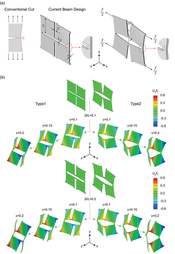
We focus on a unit cell comprising four square domains and stretch it uniaxially along one set of cuts by applying a macroscopic stress:
where is the force applied to the flexural hinges on the vertical boundaries and
denotes its cross-sectional area. The applied uniaxial stress generates identical bending moments
at all hinges, which in turn induce the rotation of all square domains by an angle
and the opening of all the cuts by an angle
. Focusing on a single square domain, it is easy to see that
Since must be balanced by the couple induced by the internal loads, we have
where is the second moment of area of each hinge about the z axis and
denotes the curvature of each bent hinge. When the width of a cut is very narrow, the length of the bent region is assumed as the hinge width
. However, we noticed that if the cut becomes wider, the effect of rigid squares becomes insignificant. Assuming that when
increases from 0 to
, contribution of rigid squares decreases linearly. When cut width reaches
and continues to increase and bent region is limited to the hinge area, we obtain
Substitution of EquationEq (2)(2)
(2) and EquationEq (3)
(3)
(3) into EquationEq (4)
(4)
(4) yields
Moreover, since the strain in the loading direction is given by
In the small deformation regime, we have
It follows that the effective Young’s modulus of kirigami sheet is
When the out-of-plane deformation of the flexural hinges becomes energetically less costly than their in-plane deformation, buckling of the beams occurs. We define the critical strain at which the out-of-plane deformation is triggered. Then strain energy density can be expressed as
, where
and
represent the in-plane and out-of-plane strain energy densities, respectively. Energy contribution due to the out-of-plane deformation is not significantly affected by cut width, and similar expression of out-of-plane deformation energy previously obtained for narrow cuts [Citation45] can also be used:
Where denotes the opening angle of a square after out-of-plane buckling. Finally, we find that
3. Experimental validation and FEM study
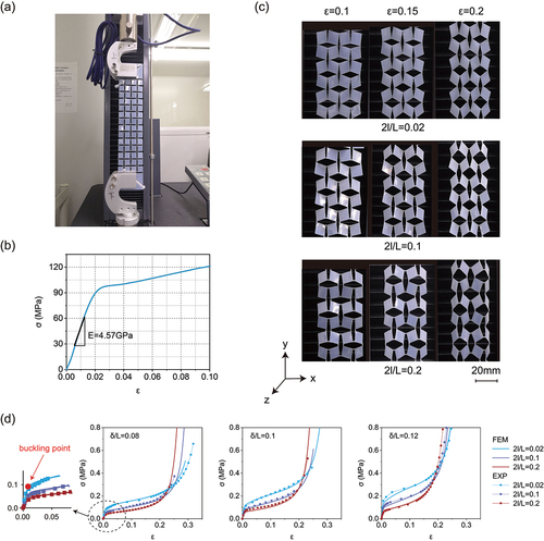
To validate the prediction of the theoretical model, we characterize the response of our kirigami structures using a mechanical testing machine (WANCE ETM502A). The material considered in this study is polyethylene terephthalate (PET), and its property is obtained by uniaxial tensile test with a 200 N load cell. Samples with a gauge length of 120 mm and width of 10 mm were fully clamped at both ends and stretched with a displacement rate of 6 mm/min up to . The stress–strain curve in ) suggests that PET has a Young’s modulus of 4.57 GPa. Moreover, 0.2% offset yield strength is measured as
, and their plastic strain
versus
is plotted up to fully plastic region. Finally, a typical Poisson’s ratio
is assumed for all the plastic sheets. The specimens considered in this study are fabricated by laser cutting an array of
mutually perpendicular cuts into PET as shown in ). First, we fabricated a line-shaped marker on the samples by laser cutting and measured the width of the cuts using an optical microscope. Multiple measurements show that the thinnest cut width is about 0.2 mm. Then, we take 0.2 mm as the design width of narrow cuts for comparison. The settings of laser cutting can be determined to minimize errors of the cut widths as much as possible. In ), we present results of samples fabricated with different cut widths
(0.2 mm, 1 mm, and 2 mm). All specimens have the same length (
) and thickness (
). These results are obtained by uniaxial tensile test equipped with a 100 N load cell.
Figure 2. Experimental and FEM study of the kirigami sheets. (a) Experiment setup and view of the perforated sheet. (b) Stress–strain curve of the plastic sheet under uniaxial tension. (c) Snapshots of the sample with at
, 0.15 and 0.2. (d) Quantitative comparison between experimental and numerical stress–strain curves. Results for different patterns with
,
.
We conduct finite element (FE) simulations using the commercial package ABAQUS/Standard 2017 to further investigate the mechanical stretchability. In all simulations, the models are discretized with 3D shell elements (S4R). Narrow cuts in the sheets are modeled as thin rectangular slits with a thickness of 0.2 mm as observed in the physical samples. Wider cuts are modeled as rectangular slits with design parameters. The material behavior of the sheets is captured using an elastoplastic model with parameters directly extracted from uniaxial tensile tests conducted on the polyester plastic sheets (i.e. Young’s modulus and yield stress
). Specifically, we take the plastic strain versus stress for the plastic sheet according to ). An elasto-plastic model (material models *ELASTIC and *PLASTIC in ABAQUS) is used with the experimentally characterized properties. Moreover, to understand the effect of plastic deformation, we also compare our results to those obtained by using a purely elastic material model with
and
.
To save the computational cost and eliminate the boundary effects, we use representative volume elements (RVEs) to simulate the 2D infinite periodic cut structures. Periodic boundary conditions (PBCs) are applied as displacement boundary conditions on the nodes of the edges while the uniaxial loads are controlled by forces on the nodes of the edges. For a specific RVE, PBCs are applied to the left and right edges, where the displacements along x and y axis on the two vertical edges are kept the same. Uniaxial loads along y-axis are applied to the top and bottom edges, where the displacements along x-axis are kept the same during deformation. On the meshed RVEs, local fine meshes are applied to all the hinge areas since these regions are highly deformed with severe stress concentration. The in-plane linear elastic response of the sheets is simulated by conducting static simulations. For out-of-plane response simulations, we use buckle module in ABAQUS to identify the critical buckling modes. After identifying the critical buckling mode, we then introduce a small imperfection in the form of the critical mode into the mesh to guide the post-buckling analysis through static/Riks algorithm in ABAQUS. We do not need to modify the mesh directly, instead, a result file will be written by buckle module. In the next step, this file containing buckling results of the mesh can be read in post-buckling analysis; meanwhile, we define the value of the small imperfection. In this way, we can obtain the result corresponding to any strain in the post-buckling process. In order to control the strain of the structures more precisely, we also use dynamic/implicit algorithm in ABAQUS, which allows for displacement controlling. Results of the two algorithms are consistent. To validate our unit cell simulations, we compare their results to those of the experimental results. Numerical snapshots for structures using elastoplastic model are reported in ). The critical strain values of the first two buckling modes are almost equal. Either of the two can be chosen to influence the direction of the instability in post-buckling analysis. In the experiment, these two types of buckled patterns occur randomly, which agrees with the simulation results.
As shown in ), we find excellent quantitative agreements between effective Young’s modulus, critical strain, and stress–strain curves, with small discrepancies caused by boundary effects. According to previous observation [Citation45,Citation46], the stress–strain curves can be divided into three stages. At the first stage, all hinges bend in-plane, resulting in a linear response. After then, the hinges generate out-of-plane buckling deformation and cause the stress a sudden departure from linearity to a plateau state, which can be considered as the second stage. Finally, all unit cells are stretched to the maximum extent, and an extra tension to the kirigami structures results in a rapid increase in stress while the strain remains almost unchanged.
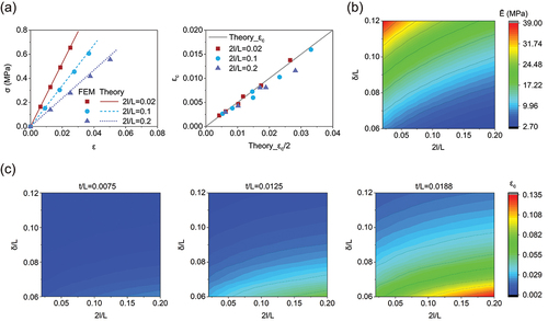
We also find excellent agreement between the numerical and theoretical results, as shown in ). Results collected in ) and ) indicate that the stiffness of the perforated sheets is reduced when the width of cuts is increased. As a result, wider cuts lead to an increase in critical strain.
Figure 3. Response of kirigami sheets subjected to uniaxial tension. (a) Comparison between numerical and theoretical effective Young’s modulus (with ) and critical strain. (b) Effective Young’s modulus of perforated sheet (with
,
). (c) Critical strain of perforated sheet (with
,
).
4. Plastic deformation in the compliant beam
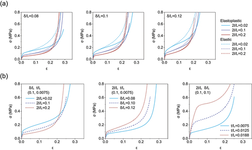
After verifying the validity of simulations, we examine the effect of plasticity and investigate the response of both elastic and elastoplastic kirigami sheets with cut width . The results reported in ) indicate that with further deformation after the initial linear regime, plastic deformation significantly affects the stress–strain response of the structures at the second deformation stage. Since the large local strain is expected to induce plastic deformation in most materials, it is important to reduce stress concentration by increasing the load bearing area. We then parametrically investigate the effect of geometric parameters (i.e.
,
, and
) on the mechanical response of the system. We simulate the response of kirigami unit cells with
,
, and
. The results of this parametric study are displayed in ). For all the considered kirigami sheets, the specific characteristics of the stress–strain curves can be significantly tuned by altering
,
, and
. The results show that our kirigami sheets are capable of constructing a set of buckling-induced 3D morphology through regulating geometric parameters and the applied strain.
Figure 4. Effect of material behavior on the response of kirigami sheets subjected to uniaxial tension. (a) Comparisons between numerical stress–strain curves obtained considering an elastoplastic (solid line) and a purely elastic (dashed line) material model. (b) Effect of the geometric parameters on the stress–strain curves of the elastoplastic kirigami sheets.
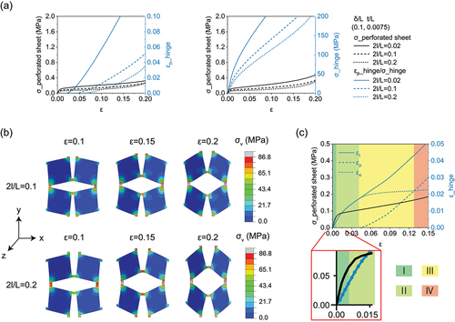
Next, we analyze the stress distribution in the structures through FEM simulations using elastoplastic and purely elastic model. ) shows the corresponding simulated von Mises stress contours of kirigami structures at the same stretching strain. By monitoring the distribution of the von Mises stress within the sheets, we find that plastic deformation initiates at the tip of hinges at the onset of buckling and then gradually expand to fully cover the hinges when the sample is fully stretched and the deformation mechanism changes from bending dominated to stretching dominated. ) shows the plastic strain occurs and increases as the sheet is stretched. We find that increasing the width of cuts can delay the generation of plastic strain at the hinge tips while the strain of the sheets is similar, and the value of plastic strain is significantly reduced in the following process. As comparison with the plastic strain model, the maximum von Mises stress at the tip of hinges using the purely elastic material property. It is clear that increasing the width of cuts reduces the stress concentration. Finally, we analyze the strain components at the hinge tips. In the case shown in ), all hinges bend in-plane at zone I, resulting in a linear response. After buckling (i.e. ), there is still no plastic deformation at zone II, and the yielding of the hinges begins approximately at
. This strain is much greater than the critical strain. Then, strain of the sheet changes from elasticity dominated (zone III) to plasticity dominated (zone Ⅳ), which reduces the stretchability of the structure. Our simulations confirm that when the width of cuts is appropriately increased, 3D reconfigurable space of the kirigami sheet is guaranteed.
Figure 5. Increase the width of cuts to improve the strength and stretchability of kirigami structures. (a) Maximum principal plastic strain using an elastoplastic material model and maximum von Mises stress using a purely elastic material model. (b) Simulated von Mises stress contours for elastoplastic sheets with ; samples show stress concentration in all the hinge areas. (c) Maximum principal strain components using an elastoplastic material model.
5. Illustration of phononic crystal metamaterials
The ability to tune wave propagation and filter specific bands of frequencies, via Bragg scattering in a periodic medium, has enabled countless applications. Using the kirigami principle is a simple, scalable, and effective approach for creating and controlling periodic structures. The kirigami-based metamaterial can be utilized as a phononic crystal when in-plane strain is induced [Citation11]. For thin plastic sheets, it is very easy to buckle during stretching, which leads to more complex pattern transformation. We focus on the tunable Bragg bandgap characteristics in their buckling-induced 3D morphology. Bloch-wave analysis is conducted using COMSOL Multiphysics 5.6 Solid Mechanics Module to compute the phononic band structure of the metamaterials with different hinges. Bragg bandgap is mainly influenced by material properties and structure parameters. Perforated sheets with are used in order to ensure the stiffness, and the density of the PET is
. Deformed RVE calculated from ABAQUS is imported into COMSOL to conduct eigenfrequency studies, which ensure the external 3D shape of a buckled kirigami sheet. The two buckling forms with different directions of the instability are both taken into consideration. Moreover, the stress distribution is concentrated almost exclusively in hinge regions, and the stress level can be controlled. Compared to the shape of kirigami sheets, stress have little effect on the bandgap characteristics.
) shows an example of unit cell composed of our rigid squares and connected hinges. It should be pointed out that although the structures we present are 3D after buckling, the periodicity direction is along the y axis. RVEs are periodically arranged with a lattice constant of , where
is the strain in the loading direction controlled by boundary conditions. The Irreducible Brillouin Zone of the lattice is
and
is the wave number within it. Via COMSOL, floquet boundary condition in the y-axis direction is applied to the deformed RVEs. The phononic bandgap is obtained by sweeping the eigenfrequency analysis. Here, only the wave propagation in the y-axis direction is considered.
Figure 6. The numerical Bragg’s elastic wave propagation bandgaps in the periodic kirigami metamaterials. (a) The periodic kirigami metamaterial with a lattice constant of . (b) Results for the deformed structure with
. (c) Results for the deformed structure with
. (d) Results for the deformed structure with different buckling patterns with
. (e) The displacement distribution in the first-order buckling deformed finite structure corresponding to the case in (c) at 500 Hz and 2700 Hz. (f) Result for the in-plane deformed structure with
.
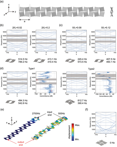
We create geometry from shell elements and rebuild Physics-controlled mesh in COMSOL to simulate 3D structures. We refine the mesh to ensure that the result of bandgap is almost independent of the element size (no more than 0.5%). -(d) shows the comparisons of numerically calculated band diagrams and forbidden bandwidths between buckled kirigami metamaterials with different geometric parameters () of hinges at the same stretching strain (
). Phononic bandgaps of forbidden frequencies, where waves could not propagate through, are denoted by the gray filled areas. There are two obvious Bragg bandgaps in the results of each structure. Wider cuts induce lower frequencies of bandgaps. Moreover, the bandgaps found in the structure with wider cuts are narrowed. When hinge width is increased, two bandgaps approach to each other. In addition, if we adjust the two buckling patterns through opposite initial perturbation, different bandgaps will be formed, which can be further confirmed by the transmission spectra obtained from the numerical simulation as shown in ). Wider range of bandgap tunability in 3D morphology provides the capability to guide elastic wave. To further demonstrate the wave propagation, we plot the displacement distributions of the finite structure in ) under the first state (frequencies marked with red circles). As shown in ), on the one hand, 500 Hz is on a passband of the guided wave mode, and thus, the elastic waves can propagate. On the other hand, 2700 Hz is in the range of the guided mode bandgap of the deformed structure, and hence, the wave propagation is suppressed at this frequency. At last, we plot the band diagram for in-plane deformed structure as a comparison in ). There is no bandgap in the same frequency range.
6. Conclusions
In conclusion, by taking into account the width of cuts, we design the kirigami cut in terms of a notch flexure with compliant beam instead of a conventional crack-shaped cut. The mechanical responses with different design parameters are studied experimentally, analytically, and numerically. With the introduction of cut width in the compliant beams, the flat kirigami sheets improve the repeatable configuration ability with tunable buckling conditions. Programmable onset of buckling-induced 3D patterns can be predicted and tuned by carefully choosing a series of geometric parameters of the sheets. Moreover, by finite element simulation, we reveal the propagation of plastic deformation from hinge tips, which can be delayed by increasing the width of cuts. Through rational design of the local hinges, we obtain a highly stretchable kirigami metamaterial with enhanced structure strength and controllable deformation as phononic crystal. By the control of hinge geometry and buckling mode in the metamaterials, we are able to filter undesirable frequencies. The insights presented here shall have a broad range of potential applications of mechanical metamaterials, including, but not limited to, noise mitigation, wave transmission and vibration control, acoustic cloaking, non-reciprocity, and even wave-based mechanical computation, with precisely controlled material stiffness and mechanical response.
Acknowledgments
This work was supported by the National Key R&D Program of China (2019YFB1311600), Natural Science Foundation of China (Grant No. 52075411 and U1913213), Shanxi Key Research and Development Program (2020ZDLGY06-11). B. L. thanks XJTU for joint-collaboration project in multi-disciplines (xhj032021014-03).
Disclosure statement
No potential conflict of interest was reported by the author(s).
Additional information
Funding
References
- Holmes DP, Yang Y. A cut above: folding and cutting advanced materials[J]. Matter. 2019;1(4):799–800. DOI:10.1016/j.matt.2019.09.005.
- YuChun H. The origin, classification and evolution of Chinese paper cutting[D]: University of Leeds, 2014.
- Shan SC, Kang SH, Zhao ZH, et al. Design of planar isotropic negative poisson’s ratio structures[J]. Extreme Mech Lett. 2015;4:96–102. DOI:10.1016/j.eml.2015.05.002.
- Mizzi L, Azzopardi KM, Attard D, et al. Auxetic metamaterials exhibiting giant negative poisson’s ratios[J]. Physica Status Solidi-Rapid Research Letters. 2015;9(7):425–430. DOI:10.1002/pssr.201510178.
- Wang GL, Sun SW, Li ME, et al. Large deformation shape optimization of cut-mediated soft mechanical metamaterials[J]. Mater Res Express. 2019;6(5). DOI:10.1088/2053-1591/aaeabc
- Hamzehei R, Zolfagharian A, Dariushi S, et al. 3D-printed bio-inspired zero Poisson’s ratio graded metamaterials with high energy absorption performance[J]. Smart Mater Struct. 2022;31(3):035001. DOI:10.1088/1361-665X/ac47d6.
- Noroozi R, Bodaghi M, Jafari H, et al. Shape-Adaptive metastructures with variable bandgap regions by 4D printing[J]. Polymers (Basel). 2020;12(3):519. DOI:10.3390/polym12030519.
- Bodaghi M, Liao WH. 4D printed tunable mechanical metamaterials with shape memory operations[J]. Smart Mater Struct. 2019;28(4):045019. DOI:10.1088/1361-665X/ab0b6b.
- Bertoldi K, Vitelli V, Christensen J, et al. Flexible mechanical metamaterials[J]. Nat Rev Mater. 2017;2(11). DOI:10.1038/natrevmats.2017.66
- Cho Y, Shin JH, Costa A, et al. Engineering the shape and structure of materials by fractal cut[J]. Proc Natl Acad Sci U S A. 2014;111(49):17390–17395. DOI:10.1073/pnas.1417276111.
- Tang YC, Lin GJ, Han L, et al. Design of hierarchically cut hinges for highly stretchable and reconfigurable metamaterials with enhanced strength[J]. Adv Mater. 2015;27(44):7181–7190. DOI:10.1002/adma.201502559.
- Sussman DM, Cho Y, Castle T, et al. Algorithmic lattice kirigami: a route to pluripotent materials[J]. Proc Natl Acad Sci U S A. 2015;112(24):7449–7453. DOI:10.1073/pnas.1506048112.
- Alderete NA, Medina L, Lamberti L, et al. Programmable 3D structures via Kirigami engineering and controlled stretching[J]. Extreme Mech Lett. 2021;43:101146. DOI:10.1016/j.eml.2020.101146.
- Chen S, Liu Z, Du H, et al. Electromechanically reconfigurable optical nano-kirigami[J]. Nat Commun. 2021;12(1):1299. DOI:10.1038/s41467-021-21565-x.
- Zhang X, Medina L, Cai H, et al. Kirigami Engineering-Nanoscale structures exhibiting a range of controllable 3D configurations[J]. Adv Mater. 2021;33(5):e2005275. DOI:10.1002/adma.202005275.
- Zhang YH, Yan Z, Nan KW, et al. A mechanically driven form of Kirigami as a route to 3D mesostructures in micro/nanomembranes[J]. Proc Natl Acad Sci U S A. 2015;112(38):11757–11764. DOI:10.1073/pnas.1515602112.
- Blees MK, Barnard AW, Rose PA, et al. Graphene kirigami[J]. Nature. 2015;524(7564):204–207. DOI:10.1038/nature14588.
- Jin LS, Forte AE, Deng BL, et al. Kirigami-Inspired inflatables with programmable shapes[J]. Adv Mater. 2020;32(33). DOI:10.1002/adma.202001863
- Dias MA, McCarron MP, Rayneau-Kirkhope D, et al. Kirigami actuators[J]. Soft Matter. 2017;13(48):9087–9092. DOI:10.1039/c7sm01693j.
- Rafsanjani A, Zhang YR, Liu BY, et al. Kirigami skins make a simple soft actuator crawl[J]. Sci Rob. 2018;3(15). DOI:10.1126/scirobotics.aar7555
- Rafsanjani A, Bertoldi K, Studart AR. Programming soft robots with flexible mechanical metamaterials[J]. Sci Rob. 2019;4(29). DOI:10.1126/scirobotics.aav7874
- Sedal A, Memar AH, Liu TS, et al. Design of deployable soft robots through plastic deformation of kirigami structures[J]. IEEE Rob Autom Lett. 2020;5(2):2272–2279. DOI:10.1109/Lra.2020.2970943.
- Yang Y, Vella K, Holmes DP. Grasping with kirigami shells[J]. Sci Rob. 2021;6(54). DOI:10.1126/scirobotics.abd6426
- Babaee S, Shi Y, Abbasalizadeh S, et al. Kirigami-inspired stents for sustained local delivery of therapeutics[J]. Nat Mater. 2021;20(8):1085–1092. DOI:10.1038/s41563-021-01031-1.
- El Helou C, Buskohl PR, Tabor CE, et al. Digital logic gates in soft, conductive mechanical metamaterials[J]. Nat Commun. 2021;12(1):1633. DOI:10.1038/s41467-021-21920-y.
- Zhang H, Wu J, Fang D, et al. Hierarchical mechanical metamaterials built with scalable tristable elements for ternary logic operation and amplitude modulation[J]. Sci Adv. 2021;7(9). DOI:10.1126/sciadv.abf1966
- Hwang DG, Trent K, Bartlett MD. Kirigami-Inspired structures for smart adhesion[J]. ACS Appl Mater Interfaces. 2018;10(7):6747–6754. DOI:10.1021/acsami.7b18594.
- Zhao RK, Lin ST, Yuk H, et al. Kirigami enhances film adhesion[J]. Soft Matter. 2018;14(13):2515–2525. DOI:10.1039/c7sm02338c.
- Fan JA, Yeo WH, Su YW, et al. Fractal design concepts for stretchable electronics[J]. Nat Commun. 2014;5. DOI:10.1038/ncomms4266.
- Song ZM, Wang X, Lv C, et al. Kirigami-based stretchable lithium-ion batteries[J]. Sci Rep. 2015;5. DOI:10.1038/srep10988.
- Tang RT, Fu HR. Mechanics of buckled kirigami membranes for stretchable interconnects in island-bridge structures[J]. Journal of Applied Mechanics-Transactions of the Asme. 2020;87(5). DOI:10.1115/1.4046003.
- Zhou X, Parida K, Halevi O, et al. All 3D-printed stretchable piezoelectric nanogenerator with non-protruding kirigami structure[J]. Nano Energy. 2020;72:104676. DOI:10.1016/j.nanoen.2020.104676.
- Evke EE, Huang C, Wu YW, et al. Kirigami-Based compliant mechanism for multiaxis optical tracking and Energy-Harvesting applications[J]. Adv Eng Mater. 2020; DOI:10.1002/adem.202001079.
- Xu Z, Jin CR, Cabe A, et al. Implantable cardiac Kirigami-Inspired Lead-Based energy harvester fabricated by enhanced piezoelectric composite film[J]. Adv Healthc Mater. 2021; DOI:10.1002/adhm.202002100.
- Sepehri S, Jafari H, Mashhadi MM, et al. Tunable elastic wave propagation in planar functionally graded metamaterials[J]. Acta Mech. 2020;231(8):3363–3385. DOI:10.1007/s00707-020-02705-8.
- Sepehri S, Jafari H, Mashhadi MM, et al. Study of tunable locally resonant metamaterials: effects of spider-web and snowflake hierarchies[J]. Int J Solids Struct. 2020;204:81–95. DOI:10.1016/j.ijsolstr.2020.08.014.
- Javid F, Wang P, Shanian A, et al. Architected materials with Ultra-Low porosity for vibration control[J]. Adv Mater. 2016;28(28):5943–5948. DOI:10.1002/adma.201600052.
- Tang YC, Yin J. Design of cut unit geometry in hierarchical kirigami-based auxetic metamaterials for high stretchability and compressibility[J]. Extreme Mech Lett. 2017;12:77–85. DOI:10.1016/j.eml.2016.07.005.
- Hwang DG, Bartlett MD. Tunable mechanical metamaterials through hybrid kirigami structures[J]. Sci Rep. 2018;8(1). DOI:10.1038/s41598-018-21479-7
- Yang Y, Dias MA, Holmes DP. Multistable kirigami for tunable architected materials[J]. Phys Rev Mater. 2018;2(11). DOI:10.1103/PhysRevMaterials.2.110601
- van Manen T, Janbaz S, Ganjian M, et al. Kirigami-enabled self-folding origami[J]. Mater Today. 2020;32:59–67. DOI:10.1016/j.mattod.2019.08.001.
- Mizzi L, Salvati E, Spaggiari A, et al. Highly stretchable two-dimensional auxetic metamaterial sheets fabricated via direct-laser cutting[J]. Int J Mech Sci. 2020;167:105242. DOI:10.1016/j.ijmecsci.2019.105242.
- Mizzi L, Salvati E, Spaggiari A, et al. 2D auxetic metamaterials with tuneable micro-/nanoscale apertures[J]. Appl Mater Today. 2020;20:100780. DOI:10.1016/j.apmt.2020.100780.
- Choi GPT, Dudte LH, Mahadevan L. Programming shape using kirigami tessellations[J]. Nat Mater. 2019;18(9):999–1004. DOI:10.1038/s41563-019-0452-y.
- Rafsanjani A, Bertoldi K. Buckling-Induced Kirigami[J]. Phys Rev Lett. 2017;8:118. DOI:10.1103/PhysRevLett.118.084301
- An N, Domel AG, Zhou JX, et al. Programmable hierarchical kirigami[J]. Adv Funct Mater. 2020;30(6):1906711. DOI:10.1002/adfm.201906711.
- Howell LL. Handbook of compliant mechanisms[M]. New York: Wiley Interscience; 2013.
- Chen GM, Magleby SP, Howell LL. Membrane-Enhanced Lamina emergent torsional joints for surrogate folds[J]. J Mech Des. 2018;6:140. DOI:10.1115/1.4039852
- Nelson TG, Zimmerman TK, Magleby SP, et al. Developable mechanisms on developable surfaces[J]. Sci Rob. 2019;4(27). DOI:10.1126/scirobotics.aau5171
- Ling MX, Howell LL, Cao JY, et al. Kinetostatic and dynamic modeling of flexure-based compliant mechanisms: a survey[J]. Appl Mech Rev. 2020;72(3). DOI:10.1115/1.4045679