 ?Mathematical formulae have been encoded as MathML and are displayed in this HTML version using MathJax in order to improve their display. Uncheck the box to turn MathJax off. This feature requires Javascript. Click on a formula to zoom.
ABSTRACT
Nanotubes form clusters and are found in curved bundles in nanotube films and nanocomposites. Separation phenomenon is suspected to occur in these curved bundles. In this study, the deformation of a single-wall carbon nanotube (SWCNT) interacting with curved bundle nanotubes is analyzed. It is assumed that the bundle is rigid and only van der Waals force acts between the nanotube and the bundle of nanotubes. A new method of modeling geometric nonlinear behavior of the nanotube due to finite rotation and the corresponding van der Waals force is developed using co-rotational finite element method (CFEM) formulation, combined with small deformation beam theory, with the inclusion of axial force. Current developed CFEM method overcomes the limitation of linear Finite Element Method (FEM) formulation regarding large rotations and deformations of carbon nanotubes. This study provides a numerical tool to identify the critical curvature influence on the interaction of carbon nanotubes due to van der Waals forces and can provide more insight into studying irregularities in the electronic transport properties of adsorbed nanotubes in nanocomposites.
Graphical abstract

1 Introduction
Carbon nanotubes have been one of the state-of-the-art research topics in last 3 decades since its discovery [Citation1]. For enhanced mechanical properties of the nanocomposites, nanofillers with high aspect ratios are sought. Higher aspect ratio results in large contact area between the fibers and the matrix and more efficient reinforcement. Due to their high aspect ratio and higher mechanical, electrical, and thermal properties, carbon nanotubes are an excellent choice as nanofillers for nanocomposites [Citation2]. Significant enhancement of electrical properties of carbon nanotube epoxy composites are attributed to higher aspect ratios of carbon nanotubes [Citation3]. Near a percolation threshold, a critical concentration of CNTs, very high values of dielectric permittivity and electric conductivity are obtained that are extremely sensitive to external parameters such as temperature, pressure, and deformations [Citation4]. For application of nanocomposites made up of CNTs as sensors, sensitivity of the electric properties to these external stimuli is advantageous [Citation5–9]. Carbon nanotube composites are being explored as sensors for structural health monitoring applications. Alexopoulos et al. (2010) studied the potential of glass fiber-reinforced polymer (GFRP) coupons with embedded carbon nanotubes as sensors for the structural health monitoring via electrical resistance measurement of carbon nanotube fibers. In another study, Al-Rub et al. (2012) have used multi-walled carbon nanotubes (MWCNT) as reinforcement in cementitious materials and observed that nanocomposites with lower concentration of long MWCNTs gives comparable mechanical performance compared to higher concentration of short MWCNTs. Freihofer et al. [2012] have proposed Raman control technique to any intermediate phase of a manufacturing process to develop enhanced novel carbon nanotube composite for structural applications. Loh and Nagarajaiah (2016) have a comprehensive review for application of carbon nanotube composites as sensors for Structural Health Monitoring applications.
As the carbon nanotubes are finding their way into composites as a structural material owing to their excellent mechanical properties, gaining more insight into the correlation between the mechanical deformations and electrical transport properties of these composites will find its application as more reliable sensors. Recent studies have shown that the electronic properties of SWCNTs are strongly dependent on their mechanical deformation [Citation10–12]. Carbon nanotubes are often treated as one-dimensional material, which is curved than being straight [Citation13]. Electrical transport through carbon nanotubes is normally discussed in terms of idealized geometrically free nanotubes unperturbed by interaction with the matrix. But the carbon nanotubes interact with surrounding material through van der Waals force, which is likely responsible for the irregularities in the electronic transport properties of adsorbed nanotubes [Citation14,Citation15]. The deformations of a nanotube under the influence of van der Waals force have been investigated [Citation16]. Due to the special form of van der Waals force, there exists ‘jump phenomenon’ once the curvature of the nanotube exceeds a certain value. As carbon nanotubes with large aspect ratios are preferred as nanofillers for nanocomposites, numerical simulations of carbon nanotubes result in large deformations. Linear FEM formulation by Li et al. [Citation16] based on small deformation theory limits its application to shorter carbon nanotubes with large curvatures only. Linear FEM formulation neglects finite rotation as a result of large deformation, and thus a more general formulation is pursued for the study of interaction of carbon nanotubes with bundle of carbon nanotubes in nanocomposites and subsequently its application as sensors.
Co-rotational formulation [Citation17–22], which uses independent coordinate system for each element, can eliminate the rigid body translation and rotation deformation of the element. Since co-rotational formulation separates rigid body motions (translations as well as rotations) from total deformations, linear elements usually restricted to small strains can be used for nonlinear computations [Citation23]. Co-rotational FEM formulation finds application for buckling and post buckling analyses of geometrically nonlinear structures. Liang et al. [Citation24] have used co-rotational finite element formulation to facilitate the required fourth-order derivatives of the strain energy required by Koiter–Newton approach for buckling analysis of geometrically nonlinear structure. In another study, Chen et al. 2006 [Citation25] have applied co-rotational total Lagrangian finite element formulation for geometric nonlinear buckling and post buckling analyses of thin-walled beams with open sections. In this paper, co-rotational formulation is used to account for geometric nonlinear effect of the nanotube due to finite rotation. For a nanotube discretized into finite elements, the individual element deformation is composed of small deformation, due to small strain, and large rigid translational and rotational deformations.
This paper is organized as follows. Theoretical background for the jump phenomenon and interaction of carbon nanotubes via van der Waals forces is given in Section 2. CFEM formulation is developed in Section 3. Results from CFEM simulations are validated using linear FEM formulation in Section 4. Numerical simulations to study ‘jump phenomenon’ are presented in Section 5 for carbon nanotube of different lengths using CFEM to highlight the advantages over the linear FEM formulation. Summary and conclusions follow in Section 6.
2 Theoretical background for carbon nanotube interactions and ‘Jump Phenomenon’
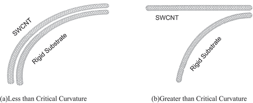
In this paper, the nonlinear interaction and resulting relative deformation between a SWCNT and a substrate of a bundle of SWCNTs, with only van der Waals force interacting between them, are considered. It is assumed that the substrate of the SWCNTs is rigid because a bundle of SWCNTs is much stiffer than a SWCNT, though for brevity and clarity only one SWCNT is included in to represent the rigid substrate. SWCNT is represented at the top of two SWCNTs in , whereas SWCNT below represents a bundle of SWCNTs to simulate the substrate. Interaction between the SWCNTs and the ‘jump phenomenon’ is explained in . During undeformed state, SWCNTs are assumed to be straight. As the SWCNTs start to deform, due to van der Waals force interaction, SWCNTs bend together till ‘critical curvature’ is reached. ) shows the deformation of SWCNT less the critical curvature where it can be observed that SWCNTs are bending together. Once the critical curvature is exceeded, SWCNTs do not bend as a unit and deformation pattern is significantly different compared to deformation just before the critical curvature. As it can be observed, after the critical curvature, the ‘substrate’ (which is represented by the SWCNT below) continues to deform while the deformation of the single SWCNT (which is represented by SWCNT at top) is significantly different in comparison of the substrate and is exaggerated in by showing it almost straight as the undeformed state.
) shows the SWCNT near the rigid substrate (model 1) and ) shows the SWCNT separated from the substrate (model 2). The transfer from model 1 to model 2, called ‘jump phenomenon,’ occurs at a critical curvature [Citation16,Citation26,Citation27]. Primarily, the ‘jump phenomenon’ during bending of carbon nanotubes is of interest in this study and other local phenomenon like buckling or rippling mode of the CNTs [Citation28] are not sought here. The main objective of this study is to represent the jump phenomenon more accurately, with due consideration being given to the geometric nonlinear behavior of the nanotube. A new method of modeling the van der Waals force and nanotube is developed using co-rotational finite element formulation [Citation20]. The position of the nanotube and the van der Waals force are updated through the progressive deformation of the nanotube for accurate computation of the critical curvature.
2.1 Beam Model for Nanotube
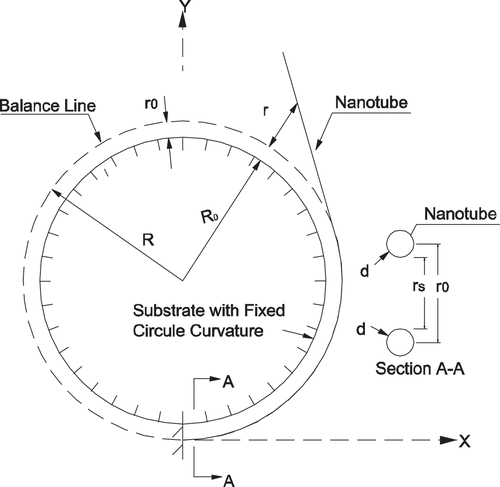
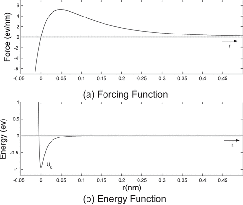
The nanotube is idealized as an elastic Euler–Bernoulli beam. The beam is fixed at the bottom and the top is free, as shown in . The substrate is fixed, and the curvature of the substrate is 1/. There is only van der Waals force of interaction between the nanotube and the substrate. The van der Waals force and energy functions are shown in . The van der Waals force per unit length is expressed as [Citation29]
where is the minimum energy in the Lennard-Jones energy potential as shown in .
is the distance between the center axis of nanotube and substrate when van der Waals force is zero and the energy is minimum, which is termed as the balance position. For a circle substrate with radius R0, the balance position of the van der Waals force along the substrate will form a concentric circle with the substrate, which is termed as the balance line henceforth. The radius of the balance line will be
.
is the distance between the balance position and the nanotube as shown in . d is the diameter of the nanotube.
3 Co-rotational finite element method (CFEM)
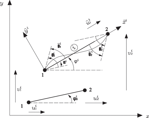
The nanotube is discretized into finite elements. Each element has two coordinate systems: a fixed global coordinate system, which is the same for every element, and a local co-rotational coordinate system, which rotates and translates with the element, as shown in . The origin of the co-rotational coordinate system of the i-th element is placed at node 1 of the element in the current configuration. The axis passes through the two end nodes of the element, and the
axis is perpendicular (counterclockwise) to the
axis and is in the same plane.
is the rotation angle of the node j of the i-th element in the co-rotational coordinate system, where
is the rotation angle of the node j of the i-th element in the fixed global coordinate system,
is the rotation angle of the i-th element in its initial configuration, and
is the rotation angle between the current
axis with the fixed x axis.
is the node deformation vector of the i-th element in the global coordinate system and
is the local co-rotational node deformation vector with
, where
is the current chord length of the i-th element between two end nodes and
is the initial length of the i-th element. In this paper, symbols with wave hat represent variables in the element co-rotational coordinate system. The transformation matrix
, defined by
, can be obtained [Citation14] as follows:
where and
.
,
are the initial coordinate values of the node j of the i-th element in the global coordinate system.
,
,
, and
are the nodal deformations of the i-th element in the global coordinate system, as shown in .
is the internal node force vector of the i-th element in the global coordinate system, and
is internal node force vector of the i-th element in the element co-rotational coordinate system.
is the axial force of the i-th element along
axis, and
and
are the moments at node 1 and node 2 of the element. The i-th element tangent stiffness matrix
in the global coordinate system is defined by
By differentiation, the first equation in EquationEq (2)(2)
(2) [Citation14,Equation15
(15)
(15) ]:
Where and
.
is the element tangent stiffness in the local co-rotational coordinate system. From EquationEq (3)
(3)
(3) and EquationEq (4
(4)
(4) ), the i-th element tangent stiffness matrix
in the global coordinate system can be expressed as
It should be noted that the relation between and
is independent on the local element assumption. Small strain is assumed to be valid for the nanotube, and the axial membrane strain of the beam is assumed to be constant. Cubic Hermitian polynomial is used to describe the lateral deformation of the element, and linear interpolation is adopted to describe the axial deformation in the element co-rotational coordinate system.
With Bernoulli beam assumption, the local tangent stiffness can be derived [Citation10]:
where E is the Young’s modulus of the nanotube, A is the section area of the nanotube, and I is the bending modulus of the nanotube.
The van der Waals force function is highly nonlinear and is nonzero only in a very small range (~0.35 nm). It is very difficult to obtain the equivalent external node forces of the van der Waals force. So, some assumptions are made in the paper. The van der Waals forces acting on i-th element are approximated by two concentrated nodal forces, which act on the nodes of the element. The absolute value of each concentrated force equals to the product of the van der Waals force and the corresponding half length of the element. The direction of the concentrated nodal force is coincident with the van der Waals forces at the corresponding nodes. The node forces can be expressed as
where and
are the angles of the van der Waals forces at node 1 and node 2 of the i-th element in the global coordinate system.
and
are the van der Waals forces at node 1 and node 2 of the i-th element in the global coordinate system. Defining
,
,
, and
and using Taylor series expansion, the van der Waals forces at node 1 and 2 can be expressed as
where and
(9)
The external forces at nodes 1 and 2 of the i-th element due to van der Waals force at can be expressed as
The principle of virtual work requires
Introducing an index matrix to relate element kinematics to global kinematics
, EquationEq (11)
(11)
(11) can be rewritten as the summation over all elements:
where n is the number of element. Expressing EquationEq (12)(12)
(12) at
:
Rearranging EquationEq (13(13)
(13) )
For any that satisfies the essential boundary condition, EquationEq (14)
(14)
(14) will hold. Defining
, which is the element stiffness matrix in global coordinate system due to nonlinear van der Waals force acting on the i-th element, the equilibrium equation for the nanotube under van der Waals force can be expressed as
In this problem, the van der Waals force is highly nonlinear and is only effective when r is less than 0.35 nm (shown in )) and the nanotube is long, which makes it extremely flexible; hence, convergence is difficult to achieve using iterative methods. Thus, an incremental load method is used for solution. First the substrate is assumed to be straight with zero curvature and the nanotube is assumed to be along the balanced position. Then the curvature of the substrate is increased and the solution for the previous step is used as the initial guess for the current step, and the convergent solution for the current step is computed. The curvature of substrate is gradually increased, and the above steps are repeated until required curvature of the substrate is reached. When the change of deformation due to unbalanced force is large, deformation control is used to obtain the solution.
4 Co-rotational finite element method (CFEM)
The stiffness of the nanotube is calculated by using (C = 2152.8
is the in-plane stiffness, based on ab initio calculations [Citation30]), where
is the diameter of the nanotube.
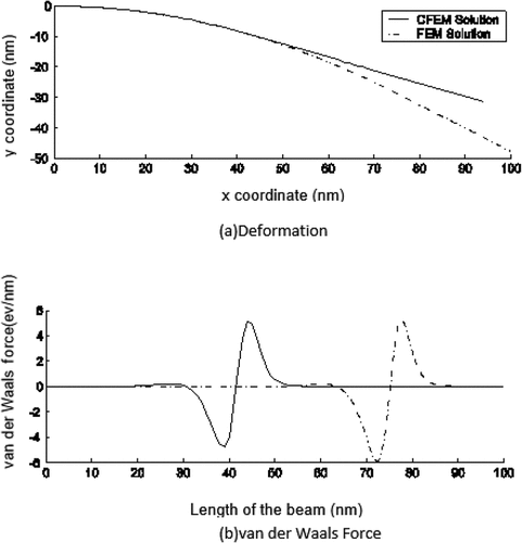
The deformation and the distributed van der Waals forces of a nanotube with 100 nm length and 1.4 nm diameter are computed with CFEM formulation and validated using Linear FEM formulation [Citation16] in . It can be observed that simulation results using CFEM match data from the linear FEM formulation. Critical curvature predicted by CFEM formulation (0.010 nm−1) compares well with the critical curvature using FEM formulation (0.0095 nm−1). Although differences between CFEM and FEM formulation are less than 5%, inclusion of higher order terms and updated van der Waals forces in CFEM formulation results in more accurate prediction of critical curvature of the substrate compared to theoretical value of 0.0099 nm−1.
5 Results and discussions
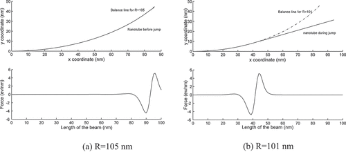
The deformations of nanotube with 100 nm length and 1.4 nm diameter are shown in . From ), it can be observed that when R equals to 105, the nanotube deformation follows the balance line very closely. Van der Waals forces can be observed at a small section of the free end when the nanotube deformation follows the balance line. For rest of the nanotube, the interaction van der Waals forces between the nanotube and the substrate are zeros. As the curvature of the substrate approaches a critical value of 0.0099 nm−1 (at R equals to 101), the nanotube begins to depart from the balance line from the free end. The van der Waals forces shift from the free end side toward the fixed end. Please note that only the location is shifted from free end to fixed end, the distribution of the van der Waals forces remains unchanged as the nanotube is departing from balanced position and returning to the straight position as shown in ) and ). During the transition from balanced position to straight position, van der Waals forces are nearly zero except for a small section. Left portion of nanotube (toward the fixed end) is still near the balanced line, and as a result, relative deformation between substrate is nearly zero. Right portion of the nanotube (toward the free end) is far away from the substrate as nanotube is trying to return to the straight position and as a result is outside the influence of van der Waals forces.
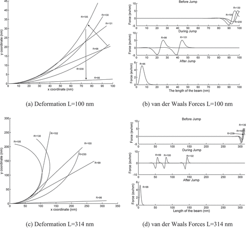
compares the CFEM simulation results for different nanotube lengths. For nanotube with 100 nm length, the displacement and van der Waals forces are shown in . From ), one can observe the jump phenomenon. As the curvature (R) of the substrate is changed from 230 to ~106, the nanotube follows the curvature of the substrate, and after a critical curvature is reached, the nanotube departs from the balanced position and try to return to the straight position for R equal to 98. At R equal to 95, the nanotube is returned to the straight position. Same observation can be made from ), where van der Waals forces are at the free end of the nanotube for curvatures (R) of the substrate from 230 to 106. As the nanotube is transitioning from balanced position to the straight position, van der Waals forces are shifting from free end to the fixed end at R equals to 101 and 98. At R equal to 95, van der Waals forces are at the fixed end, indicating the nanotube is returned to straight position. This is termed as the ‘jump phenomenon’ and results in significant change in the deformation of the nanotube after the substrate reaches a critical curvature.
For nanotube with 314 nm length, the deformations and van der Waals forces are shown in for nanotube with longer length of 314 nm. From the comparison of deformations of nanotube with longer length of 314 nm in ) with deformations of nanotube with shorter length of 100 nm, it is evident that assumption of small strains in linear FEM are not applicable to nanotubes of longer lengths. Large deformations and large rotations can be noticed at R equals to 105 and 130 for nanotube of length 314 nm in ) compared to nanotube of length 100 nm in ). An attempt to obtain the solution using linear FEM failed for nanotube of length 314 nm as the solution did not converge, whereas CFEM simulations had no issues with convergence. This clearly highlights the merits of the proposed CFEM formulation as linear elements usually restricted to small strains are used for nonlinear computations due to separation of rigid body motions (translations as well as rotations) from total deformations. CFEM formulation thus can be used for numerical simulations of nanotubes of larger aspect ratios where large deformations are expected due to longer nanotube lengths and can be used to study nanotube interactions of any shape and curvature.
6 Summary and conclusions
The deformation of a nanotube subjected to nonlinear van der Waals forces have been solved by CFEM method. For nanotubes with larger aspect ratios (length/diameters), linear FEM fails to deliver a solution. However, co-rotational finite element formulation successfully estimates critical curvature as well as deformation and van der Waals force distribution as the nanotube transitions from balanced position to the straight position. Even for nanotube of small aspect ratios, CFEM result in more accurate estimation of the critical curvature compared to the linear finite element formulation. More general CFEM formulation that is free from limitation of linear FEM can be implemented for numerical simulations of nanocomposites. Deformations of nanotubes are quite different before and after jump phenomenon and could explain the irregularities in the electronic transport properties of the nanotube observed. Nanocomposites made up of carbon nanotubes as fillers are the multipurpose structural material of tomorrow. Strong mechanical properties of the carbon nanotubes results in nanocomposites with higher structural strength. As the structure is subjected to external forces, mechanical deformations such as stretching, bending, twisting, or flattening are expected to occur in carbon nanotube bundles. Sensitivity of the electric properties to deformations of these nanocomposites can be utilized for their application as sensors. The next-generation light weight structures will be self-sensing composite structures where large amount of data will be processed to predict the failure of composite structures and their health monitoring [Citation31]. The CFEM formulation in this study provides a necessary simulation tool to gain more insight into the deformation patterns of carbon nanotubes in nanocomposites and assist in studying irregularities in the electronic transport properties of nanocomposites, which in turn will assist in application of these nanocomposites as reliable sensors for structural health monitoring. In future studies, other interesting phenomenon like formations of rings and rackets from single-wall carbon nanotubes [Citation32] as a result of sliding of SWCNTs against each other can be pursued. In a recent study by Drozov et al. [Citation33], extensive simulations are carried out using computational clusters using mDEM (mesoscopic Distinct Element Method) where it took 3 days of real time using 2240 processes on three computational clusters: Pleiades, Zhores, and Mesabi. Similar to the methodology implemented in this study, the concepts from the continuum mechanics and solid mechanics can be extended to capture the underlying physics to gain more insight into the parametric evaluation of the phenomenon otherwise observed during computationally expensive MD simulations. In future studies, different interaction formulations can be considered with the methodology presented in this study and compared with the data from the atomic simulations.
Acknowledgments
The authors wish to acknowledge the support of the Texas Institute for the Intelligent Bio-Nano Materials and Structure for Aerospace Vehicles, funded by NASA Cooperative Agreement No. NCC-1-02038.
Disclosure statement
No potential conflict of interest was reported by the author(s).
Additional information
Funding
References
- Iijima S. Helical microtubules of graphitic carbon. Nature. 1991;354(6348):56–58.
- Kapadia RS, Louie BM, Bandaru PR. The influence of carbon nanotube aspect ratio on thermal conductivity enhancement in nanotube-Polymer composite. J Heat Transfer. 2004;136(1):011303.
- Shen JT, Buschhorn ST, De Hosson JTM, et al. Pressure and temperature induced electrical resistance change in nano-carbon/epoxy composites. Compos Sci Technol. 2015;115(8):1–8.
- Shehzad K, Dang ZM, Ahmad MN, et al. Effects of carbon nanotubes aspect ratio on the qualitative and quantitative aspects of frequency response of electrical conductivity and dielectric permittivity in the carbon nanotube/polymer composites. Carbon. 2013;54:105–112.
- Hu N, Fukunaga H, Atobe S, et al. Piezoresistive strain sensors made from carbon nanotubes based polymer nanocomposites. Sensors. 2011;11(11):10691–10723.
- Alexipoulos ND, Bartholome C, Poulin P, et al. Structural health monitoring of glass fiber reinforced composites using embedded carbon nanotube (CNT) fibers. Compos Sci Technol. 2010;70(2):260–271.
- Al-Rub RKA, Ashour AI, Tyson BM. On the aspect ratio effect of multi-walled carbon nanotube reinforcements on the mechanical properties of cementitious nanocomposites. Constr Build Mater. 2012;35:647–655.
- Freihofer G, Liang F, Mohan B, et al. Ex-situ raman spectroscopy to optimize the manufacturing process for a structural MWNT nanocomposite. Int J Smart Nano Mater. 2012;3(4):309–320.
- Loh K, Nagarajaiah S. Innovative developments of advanced multifunctional nanocomposites in civil and structural engineering. Cambridge UK: Elsevier Science & Technology; 2016.
- Collins PG, Bradley KB, Ishigami M, et al. Extreme oxygen sensitivity of electronic properties of carbon nanotubes. Science. 2000;287(5459):1801–1804.
- Akita S, Nakayama Y, Mizooka S, et al. Nanotweezers consisting of carbon nanotubes operating in an atomic force microscope. Applied Physics Letter. 2001;79(11):1691–1693
- Dequesnes M, Rotkin SV, Aluru NR. Calculation of pull-in voltages for carbon nanotube-based nanoelectromechanical switches. Nanotechnology. 2002;13(1):120–131.
- Harris PJ Carbon nanotube science synthesis, properties, and applications, 2009. Cambridge University Press, Cambridge UK.
- Hertel T, Walkup RE, Avouris P. Deformation of carbon nanotubes by surface van der Waals forces. Phys Rev B. 1998;58(20):13870–13878.
- Peng S, Cho K. Chemical control of nanotube electronics. Nanotechnology. 2000;11(2):57–60.
- Li Z, Dharap P, Nagarajaiah S, et al. Nonlinear analysis of a SWCNT over a bundle of nanotubes. Int J Solids Struct. 2004;41(24–25):6925–6936.
- Meek JL, Qiang X. A study on the instability problem for 2D-frames. Computer method in applied mechanics and engineering. 1996;136(3):347–361
- Hsiao KM, Lin JY, Lin WY. A consistent co-rotational finite element formulation for geometrically nonlinear dynamic analysis of 3-D beams. Computers methods in applied Mechanical engineering. 1999;169(1–2):1–18
- Hsiao KM. Corotational total Lagrangian formulation for three-dimensional beam element. AIAA. 1992;30(3):797–804.
- Belytschko T, Liu WK, Moran B. Nonlinear finite elements for continua and structures. England: John Wiley & Sons Ltd., West Sussex; 2000.
- Battini JM. Co-rotational beam elements in instability problems. technical reports from Royal Institute of Technology. Department of Mechanics. Stockholm Sweden; 2002. p. SE–100 44.
- Criseld MA. Nonlinear finite element analysis of solids and structures. Vol. 1. Chichester England: Essentials, Wiley; 1991.
- Gruttmann F, Sauer R, Wagner W. A geometrical nonlinear eccentric 3D-beam element with arbitrary cross-sections. Computational Methods in applied mechanics and engineering. 1998;160(3–4):383–400
- Liang K, Ruess M, Abdalla M. Co-rotational finite element formulation used in the Koiter-Newton method for nonlinear buckling analyses. 2016;Finite Element in Analyses and Design. 116:38–54.
- Chen HH, Lin WY, Hsiao KM. Co-rotational finite element formulation for thin-walled beams with generic open section. Computational Methods in applied mechanics and engineering. 2006;195(19–22):2334–2370
- Yakobson BI, Couchman LS. Persistence length and nanomechanics of random bundles of nanotubes. J Nanopart Res. 2006;8(1):105–110.
- Yakobson BI, Couchman LS. Carbon nanotubes: supramolecular mechanics. In S, Et. Al JA, editors. Encyclopedias of nanoscience and nanotechnology, Marcel Dekker, New York. New York, USA: Marcel Dekker Inc. 2004. p. 587–601.
- Nikiforov I, Zhang D-B, James RD, et al. Wavelike rippling in multiwalled carbon nanotubes under pure bending. Appl Phys Lett. 2010;96(12):123107. 3pages.
- Israelachvili J. Intermolecular and surface forces. 2nd edition ed. Salt Lake City, Utah, USA: Academic press; 1992.
- Kudin KN, Scuseria GE, Yakobson BI. C2 F,BN, and C nanoshell elasticity from ab initio computations. Phys Rev B. 2001;64(23):235406/10.
- Zappino E, Carrera E. Advanced modeling of embedded piezo-electric transducers for the health-monitoring of layered structures. Int J Smart Nano Mater. 2020;11(4):325–342.
- Wang Y, Semler MR, Ostanin I, et al. Rings and rackets from single-wall carbon nanotubes: manifestations of mesoscale mechanics. Soft Matter. 2014;10(43):8635–8640.
- Drozdov G, Ostanin I, Xu H, et al. Densification of single-walled carbon nanotube films: mesoscopic distinct element method simulations and experimental validation. J Appl Phys. 2020;128(18):184701.

