
 ?Mathematical formulae have been encoded as MathML and are displayed in this HTML version using MathJax in order to improve their display. Uncheck the box to turn MathJax off. This feature requires Javascript. Click on a formula to zoom.
ABSTRACT
Smart structures have the advantages of high system integrity and diverse sensing capabilities. However, the labor-intensive and time-consuming fabrication process hinders the large-scale adoption of smart structures. Despite recent attempts to develop sensor-embedded structures using 3D printing technologies, the reported smart structures generally suffer from the complex fabrication process, constrained part size, and limited sensing modality. Herein, we propose a workflow to design and fabricate novel smart structures via multimaterial fused deposition modeling (FDM)-based 3D printing. More specifically, conductive filaments with tailorable mechanical and electrical properties, e.g. piezoresistive effects, were developed. Additionally, the printing process was optimized for processing soft filaments with Young’s modulus around 2 MPa, resolving the issue of filament buckling. Furthermore, the potential applications of the proposed workflow were showcased using three design cases, i.e. biaxial strain sensor, smart tire, and cable-driven soft finger with multiple sensing capabilities. This workflow provides a cost-effective and rapid solution for developing novel smart structures with soft materials.
Graphical Abstract
1. Introduction
Smart structures integrate structural and sensing components into one system that can respond to external stimuli such as light [Citation1], humidity [Citation2], mechanical force and deformation [Citation3]. Such an integrated system possesses the ability to sense, react, and even adapt to its surrounding environment. Thus, it has gained wide attention in the field of soft robotics [Citation4,Citation5], health monitoring [Citation6,Citation7], and construction industry [Citation8,Citation9], etc.
Conventional methods fabricate structures and sensors separately, and then assemble these multiple parts into a smart structure. The sensors are fixed to the surfaces of a structure by either pasting or welding. Such a process is labor-intensive and time-consuming. More importantly, this multi-step approach limits the design complexity and jeopardizes the system integrity of smart structures. Thus, the current manufacturing method is considered a bottleneck that limits the performance and functionality of smart structures.
The advent of additive manufacturing, also known as 3D printing, offers unparalleled design freedom for smart structures [Citation10]. The layer-wise nature of additive manufacturing allows the fabrication of structures with complex geometries and heterogeneous materials, which are otherwise unattainable. Previous efforts have been made to explore the use of 3D printing technologies for fabricating multimaterial and multifunctional smart structures in a single-step process. These functions include sensing, transducing, thermal management, and electromagnetic [Citation11]. Typical examples include 3D printed strain sensors [Citation12–14], flexible circuits [Citation15,Citation16], and heating units [Citation17,Citation18], etc. These smart structures were realized by 3D printing technologies such as direct ink writing (DIW), digital light processing (DLP), and selective laser sintering (SLS). Meanwhile, hybrid 3D printing is recently proposed as a new method to integrate dissimilar materials and embed active components for functionality [Citation11]. For example, the combination of DIW and pick-and-place devices for producing soft electronics [Citation19], the combination of SLS and aerosol jet printing for fabricating a multifunctional safety cage of drones [Citation20]. However, these 3D printing technologies require either significant capital expenditure or specific knowledge on material synthesis as well as hardware modification or even building. In smart structure fabrication using fused deposition modeling (FDM), smart filaments are often developed through material compositions, e.g. mixing, instead of material synthesis. In addition, modifications of FDM apparatus, e.g. the feeding system modification, cost lesser and are easier to implement.
In comparison, fused deposition modeling (FDM)-based multimaterial 3D printing has received significant attention for fabricating smart structures [Citation21,Citation22] due to its high scalability, accessibility, and affordability. The FDM-based 3D printing technique can fabricate structures ranging from centimeters to meters without increasing the cost per unit volume significantly. In the printing process, thermoplastic filaments are introduced into a printer, melted in the print head, extruded through a nozzle or orifice, and then deposited along with a user-defined pattern. Multiple materials can be selectively deposited where they are needed for specific designs [Citation23]. The most widely used filaments in FDM are acrylonitrile butadiene styrene (ABS) and polylactic acid (PLA). However, these hard plastics have low ductility and cannot be used for applications requiring large deformations. For the above applications, flexible filaments such as thermoplastic elastomers (TPE) and thermoplastic polyurethane (TPU) are often used. In terms of delivering functionality, considerable research has focused on either (i) designing the deformable structures [Citation24,Citation25] or (ii) developing metamaterials [Citation26]. Previous research found that composites of these elastomers and conductive particles, e.g. carbon black (CB) [Citation27,Citation28], possess good abilities for sensing strains. However, the potential of customizing filaments with tailored mechanical and electrical properties is not fully explored. Also, printing these soft filaments with FDM often encounters challenges such as kinking and buckling. The insufficient feed force and low Young’s modulus make it difficult to push these filaments through the nozzle smoothly, and thus the printing process fails. These research gaps necessitate a systematic study to streamline the development process of smart structures with embedded flexible sensors using FDM, from material preparation, characterization, printing, until testing.
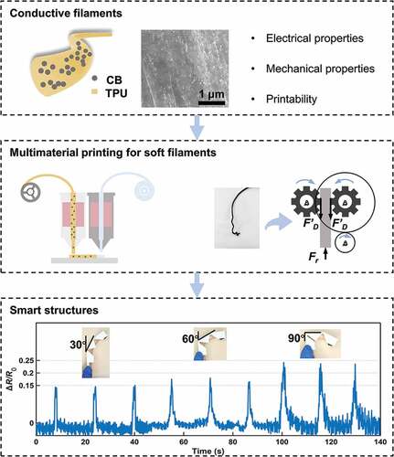
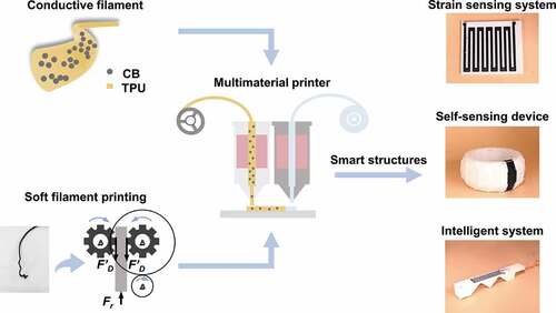
The main contribution of this work is a design and fabrication workflow based on multimaterial FDM 3D printing for developing smart structures that include flexible sensors, exhibit tailorable functionality, and possess high structural integrity. The objectives of this study are threefold. Firstly, the study presents a new approach to produce conductive flexible filaments with tailorable mechanical and electrical properties, broadening the material palette for FDM 3D printing. Secondly, we discuss the fundamental mechanisms of failures found in the printing of soft filaments and propose corresponding solutions, including filament feeding mechanism innovation, filament printability improvement, and print parameter optimization. Thirdly, by taking advantage of FDM-based multimaterial 3D printing, both structural and sensing components are fabricated in a one-step process, retaining the system integrity. To demonstrate the feasibility and versatility of the workflow, we showcase three scenarios for inspiring future applications in the field of smart structures, as shown in .
Figure 1. Workflow of FDM-based multimaterial 3D printing for developing smart structures.
2. Materials and methods
2.1. Material preparation
The functional filament comprises TPU (from BASF, Germany, Mw = 80000) as matrix and CB powders (from TIMCAL, Switzerland, Super P®) as filling particles. These CB aggregates have diameters in the range of 150 nm to 200 nm. The volume conductivity of the CB powders is of 10–15 S/cm. Compared with fillers with high aspect ratios, the conductive network of CBs can easily be broken during stretching, and thus the electrical resistance changes with high sensitivity. Meanwhile, the CB powders are much cheaper than graphene or carbon nanotubes. Therefore, this study utilizes CB powder as the functional material due to their good sensing performance and low cost. The composite filaments were prepared with the following procedure. Firstly, raw materials in the form of powder were dried in a vacuum oven for 10 hours at 50°C. Then, TPU and CB powders were mixed in a ball milling machine (F-P400E, Hunan Focucy Experimental Instrument Co., Ltd) for 3 hours at 540 rpm. Then, filaments with a consistent diameter of 1.75 ± 0.05 mm were extruded by a desktop filament extruder (Wellzoom, Shenzhen Mistar Technology Co., Ltd). A series of filaments with different CB contents, i.e. 0, 1, 3, 5, 10, and 20 wt.%, were prepared following the above procedure. As shown in ), the scanning electron microscope (SEM) photograph of CB/TPU filaments shows a uniform distribution of CB powders within the matrix.
Figure 2. Electrical and mechanical properties of CB/TPU filaments with different CB contents. (a) The distribution of CB powders of CB/TPU composites (10 wt.%) in the SEM micrograph. (b) The conductivity of the CB/TPU filaments. (c) Stress-strain behavior of the CB/TPU filaments. (d) The fracture strain and Young’s modulus of the CB/TPU filaments.
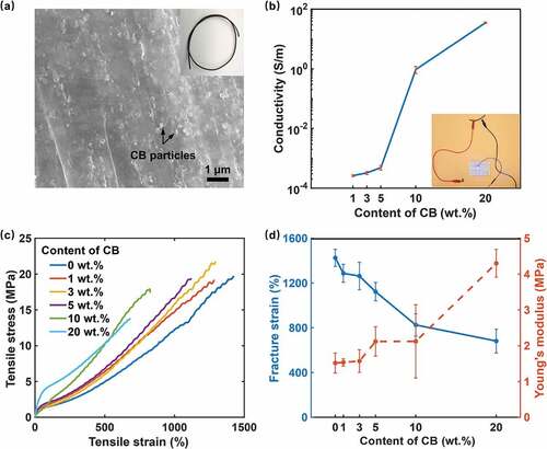
) shows the conductivity of these filaments varying from 10−4 to 102 S/m (TH2832, Changzhou Tonghui Electronic Co., Ltd., China) by tuning the CB content. The electrical conductivity was determined through Equation σ = L/(R × S), where σ is the electrical conductivity (S/m), R is the resistance of the sample (Ω), L is the length of measured sample (m), and S is the cross-sectional area of the sample (m2) [Citation29]. Meanwhile, the mechanical properties of these filaments were characterized on a uniaxial tensile testing machine (XLD-100E, Guangzhou Precision Control Testing Instrument Co. Ltd., China). All measurements in this study were conducted at room temperature. ) shows the tensile stress−strain behavior of CB/TPU composites with different CB contents. Young’s modulus was calculated by the initial 2.5% strain region where the stress-strain relationship is linear. The fracture strain and Young’s modulus with error bars calculated by the stress−strain behavior are shown in ). The increase in CB content from 1 wt.% to 20 wt.% leads to the decrease in fracture strain and increases in Young’s modulus. The achieved wide range of tailorability in electrical and mechanical properties manifests the feasibility to customize filaments for satisfying diverse requirements from sensing applications.
2.2. 3D printing of soft filaments
Although the FDM process is well-established, printing of soft filaments with Young’s modulus less than 10 MPa remains challenging. The filament is fed into a heated nozzle using a pinch roller mechanism and then deposited onto the substrate during the printing process. However, soft filaments usually cannot be smoothly pushed through the nozzle due to their insufficient stiffness. Once the filaments experience a shear deformation, it will sneak from the gap between the duct and the pinch roller system and thus the printing process will fail. To resolve the issue, we took countermeasures regarding filament feeding mechanism, filament printability, and print parameters.
2.2.1. Filament feeding mechanism
The standard feeding mechanism comprises a drive wheel and a pinch wheel to apply force to the filament, as shown in ). The drive wheel has a knurled surface to provide sufficient friction to feed the filament into the liquefier without slippage. In a steady-state extrusion process, the required force from the pinch wheel system to push the filament is:
Figure 3. The filament feeding mechanism of an FDM 3D printer. (a) Analysis of forces and moments applied to a soft filament when it enters the liquefier through a standard pinch wheel mechanism, and two typical failure mechanisms, i.e. shear and bending failures, during the print. (b) Analysis of forces and moments applied to a soft filament when it enters the liquefier through a specialized flexion BMG extruder. Gear 1 is fixed on the extruder step motor shaft. Gears 2 and 3 compose a double-knurled drive wheel system that pushes the filament through the liquefier. The gear ratio of this gear train is 3:1.
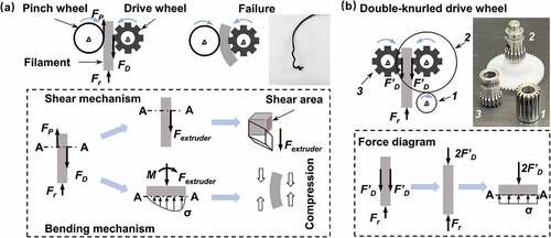
where FD is the feed force between the drive wheel and filament, FP is the friction force between the pinch wheel and filament, Fr is the flow resistance through the nozzle, and A is the cross-sectional area of the filament.
There are two typical failure mechanisms within the print of soft filaments, i.e. shear and bending failures, as shown in ). The former occurs when the supplied force Fextruder divided by the shear area causes the shear deformation. The shear area is the filament surface inscribed by the drive wheel surface profile. Meanwhile, the asymmetrical stress distribution at section A-A cause differential length changes around the section and thus result in arc-like bending of the filament. We estimated the stress distribution with the flow resistance Fr from reference [Citation30] and the drive wheel feed force FD from an actual extruding motor. For the stress difference of about 10 MPa, hard plastics, such as PLA with Young’s modulus of about 2.6 GPa, exhibits a negligible deformation. However, for soft plastics, such as TPE with Young’s modulus of about 10 MPa, the strain difference reaches 100% and thus causes bending failure. Therefore, we adopted the specialized flexion extruder, called Bondtech Mini Geared (BMG) extruder, for mitigating the above two failures of soft materials. Such extruder has a double-knurled drive wheel system, providing unidirectional forces, as shown in ). The filament segment is like a vertical beam and subjects to an axial load. The force acting on the filament along the vertical direction is:
Based on the above discussion, a multimaterial FDM 3D printer was utilized with such BMG direct-drive extruder equipped on both printing heads (TENLOG TL-D3 Pro, Tenglong 3D Technology Co., Ltd) to resolve the printing issues.
2.2.2. Printability of filaments
PLA is the most common FDM printing material. One of the advantages of PLA is that it possesses sufficient stiffness. On the other hand, it has low ductility and cannot bear large deformations. Therefore, we proposed a soft filament printing criterion, compared the rheological properties of PLA (hard plastic) and TPU (soft material), and demonstrated the printability. This workflow can be used to check the printability of any filaments with PLA as a reference.
) shows the configuration of the adopted FDM printer with BMG direct-drive extruder. Since the unsupported section of filament between the BMG extruder and liquefier subjects to an axial load, it can be considered as a pin-ended axially loaded column, as shown in ). During extrusion, if the flow resistance through the nozzle exceeds the critical load for the filament, buckling happens and the printing process stops. The buckling criterion for an elastic beam [Citation31] is defined by Euler’s analysis for pin-ended boundary condition as follows.
Figure 4. The typical configuration of an FDM 3D printer. (a) The overall configuration and process of FDM 3D printing. (b) The unsupported section of filament between the BMG extruder and liquefier subjects to an axial load and can be considered as a pin-ended axially loaded column. (c) The flow of materials through the die. Zone 1: a cylindrical zone with an interior diameter of the liquefier around the filament diameter. Zone 2: a convergent part of the nozzle. Zone 3: the die of the nozzle with a small diameter.
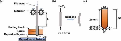
where σcr is the critical buckling stress, E is the elastic modulus of the material at ambient temperature, L is the distance between the center of the wheels and the entry of the liquefier, as shown in ), R is the radius of the filament, the quantity L/R is the slenderness ratio of the column.
For steady flow conditions, the pressure drop ΔP should consist of three zones of the nozzle, as illustrated in ), viz. Zone 1: a cylindrical zone with an interior diameter of the liquefier around the filament diameter. Zone 2: a convergent part of the nozzle. Zone 3: the die of the nozzle with a small diameter. The total pressure drop ΔP can be calculated by the Hagen-Poiseuille equation [Citation32]:
where η is the viscosity of the material, Q is the volumetric flow rate, Q = πr2v, r is the radius of the die, v is the print speed and considered as a constant for a given feed rate, l is the tube length of Zone 3, k is the coefficient between the pressure drop of Zone 3 and total pressure drop. The pressure drop ΔP depends on the viscosity of the filament, nozzle geometry, orifice size and volumetric flow rate. To avoid buckling, the critical load should exceed the flow resistance:
Therefore, the buckling criterion can be conducted from Equations (3), (4) and (5):
Equation (6) delineates the limits of the feeding system of an FDM 3D printer and thus suggests the printability of a material from its mechanical and rheological properties. According to this criterion, filaments with the value of E/η over the critical value can avoid buckling and are suitable for printing.
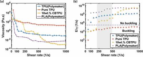
Next, the printability of the homemade filaments was investigated. The rheological properties of commercial TPU (PolyFlexTM PLA, Suzhou Polymaker Co., Ltd), homemade pure TPU, 10 wt.% CB/TPU, and commercial PLA (PolyLiteTM PLA, Suzhou Polymaker Co., Ltd) filaments were characterized by a rotational rheometer (HAAKE MARS 40, Thermo Fisher Scientific Inc) at their printing temperatures, i.e. 200°C, 190°C and 215°C, respectively. The shear rate examined was up to 1000 1/s, covering the typical range of shear rates that the molten filament experienced during printing [Citation33,Citation34]. The measurement results are summarized in ). It is observed that the pure TPU shows the highest viscosity at all shear rates, while the commercial TPU has a higher viscosity. Meanwhile, the CB/TPU filament has a higher viscosity than PLA in the low shear rate regime and a lower viscosity in the high shear rate regime. Then, the buckling index E/η of each filament, indicating its printability, was calculated according to Equation (6). The threshold of buckling is marked as a dotted blue line, as shown in ). Filaments with a buckling index larger than this threshold are printable and vice versa. According to computational fluid dynamic simulations, the maximum shear rate is 484 1/s for a 0.4 mm nozzle under the print speed of 25 mm/s, occurring at the exit of the nozzle. The minimum shear rate is 210 1/s based on the reported values in references [Citation33–35]. It is found that the values of E/η of pure TPU are lower than the buckling threshold in the above range of shear rates, indicating poor printability. In contrast, the commercial TPU possesses good printability because the additives make the filament less viscous and more rigid. What’s more, the 10 wt.% CB filament demonstrates a similar printability with the commercial TPU and PLA filament. This can be explained by the additional CB powder in the composite, which increases Young’s modulus and decreases the viscosity of filament. The reason for choosing 10 wt.% CB/TPU will be discussed in Section 3.1.
Figure 5. The rheological properties and printability of filaments. (a) Viscosity under different shear rates measured by the rotational rheometer at the liquefier temperature of commercial TPU, homemade pure TPU, 10 wt.% CB/TPU, and PLA filaments. (b) Buckling analysis performed on commercial TPU, homemade pure TPU, 10 wt.% CB/TPU, and PLA filaments. The gray box highlights the shear rate region for the 0.4 mm nozzle during extrusion. The dotted line separates the data points into the no buckling region and buckling region.
2.2.3. Print parameters
In addition, print parameters, especially the feed rates, are tuned for the homemade soft CB/TPU filaments, as summarized in . The extruder must feed the filament at a proper velocity, providing sufficient force to overcome the flow resistance in the liquefier. According to reference [Citation36], a slow feed rate can provide a larger driving force. Therefore, the print speed was set to 25 mm/s throughout the whole printing process. Such slow and consistent feed rates can effectively overcome the flow resistance of the melt and mitigate the clogging issues. Moreover, the retraction distance was set to 4 mm. Heavy stringing issues occur when the retraction distance is smaller than this optimal value, whereas kinking issues are observed if the retraction distance is above this value. With these configurations, soft filaments can be successfully printed.
Table 1. Print parameters for the multimaterial FDM 3D printing.
3. Results and discussion
3.1. Sensing property characterization
As shown in ), a thin-wall vase was fabricated with a 10 wt.% CB/TPU filament, which has a Young’s modulus of 2 MPa. With the print speed of 25 mm/s, the fabrication of vase costs around 36 minutes. Meanwhile, the resistance of the vase changed with the structural deformation, reflected by the luminance of a LED. To further investigate the resistance variation under deformation, we measured the real-time resistance of a CB/TPU sample while it was under uniaxial tensile loading. The electrical resistance of a sample was characterized on an LCR meter (TH2810B+, Changzhou Tonghui Electronic Co., Ltd., China). The uniaxial tension was performed on a tensile testing machine (XLD-100E, Guangzhou Precision Control Testing Instrument Co. Ltd., China). The test sample was designed with a gauge length of 32 mm, a width of 4 mm, and a thickness of 0.5 mm. Composites with low CB content, i.e. less than 5 wt.%, are close to the electrical percolation threshold generating a noisy electrical signal. Thus, this study tested samples with 5, 10 and 20 wt.% CB content which are over the threshold, and the results are shown in ). The strain was examined from 0% to 150%, covering the typical range of deformation that the flexible sensor experiences. In this range, all CB/TPU composites exhibit a monotonous growth on ΔR/R0, where R0 is the electrical resistance of the origin state, ΔR is the change of resistance when a mechanical strain is applied. Moreover, a larger deformation is needed to achieve the same resistance response for composites with a higher CB content. This can be explained by the percolation theory that a higher filler content emerges a larger number of percolative networks. A greater degree of deformation within the system is required to disconnect these conductive paths [Citation37]. In addition, the slope of the resistance-strain curve, called the gauge factor (GF, GF = ΔR/(R0·ε), where ε is the mechanical strain), indicates the sensitivity of materials. It is observed that the GF of measured samples is not constant during the stretching process, manifesting the dependency of sensitivity on strains. This phenomenon can be explained by two mechanisms: the changes in contact resistance between carbon nanostructures and the creation/destruction of conductive networks. In ), the resistance fluctuates when the strain starts to change. Therefore, the calculated GF values under small strain exhibit an obviously unstable stage.
Figure 6. Sensing property characterization of printed specimens. (a) The conductivity of a thin-shell vase printed with a 10 wt.% CB/TPU filament. (b) Sensing property characterization with different CB contents. (c) Resistance response of the 10 wt.% CB/TPU filament under cyclic loads. (d) The fast response of the 10 wt.% CB/TPU filaments under 10% strain loading.
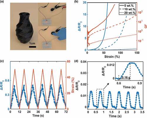
Benefiting from the high sensitivity and wide range of resistance responses, this study chose filaments with 10 wt.% CB powders as the sensing material. The performance of the filaments was investigated. As shown in ), the resistance of samples increases during stretching periods and decreases during releasing periods with a strain rate of 1.5 min−1 under cyclic loads, showing high repeatability and good stability. ) indicates that when a 10% strain was loaded with a speed of 1000 mm/min, the estimated response time was of about 160 ms. This fast response is adequate to sense dynamic changes of structural deformation.
3.2. Smart structures with embedded flexible sensor
In this section, a workflow is proposed to design and fabricate novel smart structures based on the multimaterial FDM and conductive filaments. The design freedom of this workflow is beyond the ceiling of conventional methods because smart structures and sensors can be customized in terms of function, layout, and sensitivity. With this one-step workflow, structural and sensing components can be simultaneously fabricated in a fully automated printing process without manually assembling of these two components. In addition, three representative smart structures were created using the proposed workflow to exemplify its potential applications.
3.2.1. Biaxial strain sensor
In the first embodiment, we fabricated a double-layer strain sensor to demonstrate the feasibility of the workflow, as shown in ). The strain sensor was modeled after a biaxial strain rosette, which has two orthogonal circuits in each layer. Such multi-layer sensors were originally constructed by molding channels of the prescribed design in each layer, laminating those individual layers together, and then manually assembling the embedded channels [Citation38]. By taking the advantage of the multimaterial FDM, the multi-layer sensors can be produced in a single-stage printing process.
Figure 7. Application of the flexible biaxial strain sensor. (a) Illustration of the biaxial strain sensor consisting of two individual circuits oriented precisely 90° apart. The circuits are printed with CB/TPU filaments and the substrate is printed with commercial TPU filaments. (b)-(c) ΔR/R0 plots of two sensing circuits for two types of deformation.
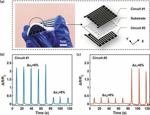
The circuit and substrate have a thickness of 1 mm and 0.5 mm, respectively. The circuit shares a similar design of conductive paths with the foil strain gauge. The orientation of the strain sensing region, i.e. the gauge grid, was defined by the principal strain direction. The grid along the length direction should be long and slender to achieve a higher gauge factor. In this case, the length/width ratio of each grid line is 19:1. Meanwhile, the strain sensor should be insensitive to the strain that is perpendicular to the direction of the gauge length. However, there is an unavoidable resistance variation responding to transverse strain due to the small amounts of strain-sensitive material in the end loops and Poisson’s effect on the grid. The strain response of the sensor was characterized by applying strains in two perpendicular directions: the X and Y axes. The prototype was gradually bent up to 8% strain in the X and Y direction, separately. The resistance changes of the two circuits were measured, as shown in . The calibration results for both axes showed repeatable sensor signals in strain sensing. More specifically, the first circuit exhibits high GF along the X-direction and low GF along the Y-direction. While the second circuit shows an opposite trend under the same condition. This can be explained by the orthogonal layout of the sensing circuits. With this biaxial strain sensor, strains from different directions can be measured. Users can simultaneously estimate the direction and magnitude of the strain by applying a decoupling algorithm. Even though the mechanical stability of the sensor still needs to be improved, the flexibility of creating free-designed sensors shows attractive potential to be applied in any strain sensing system, e.g. the three-dimensional sensor in a structural health monitoring system.
3.2.2. Smart tire
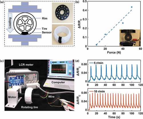
Tire-road contacts are the only interface between vehicles and roads and thus significantly influence vehicle dynamics. Sensing these tire-road interactions can provide valuable information for the development of autonomous vehicles [Citation39]. However, standard tires are still passive vehicle components that cannot perceive their states, e.g. the vertical load. In the second design case, we demonstrate the use of the proposed design and fabrication workflow for developing a smart tire with both load-bearing and sensing functions.
As shown in ), the designed smart tire has a sensing area located on the thread area, spanning over 0.46 radian in the circumferential direction and crossing the entire cross-section of the tire. During fabrication, the interior fill percentage of the tire is 15% in printing so that the whole structure will bear the vertical load, not the material itself. When the tire was loaded, the sensor was deformed in both radial and circumferential directions, causing changes in its cross-sectional area and length. The performance of the fabricated smart tire was evaluated in both static and rolling conditions. ) depicts the resistance changes measured under the static condition with different loads. ΔR/R0 increases monotonically with force imposed on the tire. Furthermore, a test rig for the dynamic condition was built to measure the resistance response of a rotating tire, as shown in ). The tire was connected to a data acquisition system by external wiring through a slip ring. The inner and outer rings were connected to the tire sensor and LCR meter, respectively, to transmit the electrical signal from a rotating tire. During spinning, the tire is always contacting with the ground. ) indicates that the sensor can detect the frequency of sensing area contacting with the ground, thus the rotation speed can be estimated. Meanwhile, the value of ΔR/R0 is nearly constant at peaks of the curve, indicating a constant wheel load applied. Based on the correlation between the resistance and force, as mentioned in ), dynamic loads of the tire can be estimated with real-time monitored ΔR/R0 data. With ΔR/R0 around 0.075 at each peak, the load under the dynamic test was estimated at around 15 N. The smart tire offers a solid and reliable data source for monitoring the subtle signals of structure states. This case envisions a physical framework of engineering structures using self-sensing devices that enable zero down-time.
Figure 8. Application of a smart sensing tire. (a) Scheme of the static load testing of the sensing tire. The sensor is printed with CB/TPU filaments, and other parts are printed with commercial TPU filaments. (b) The ΔR/R0 response of the smart tire for different load conditions. (c) Scheme of the dynamic load testing platform of the rotating tire. (d) ΔR/R0 plots of the sensing tire with time when the tire was rotating at different speeds.
3.2.3. Cable-driven soft finger
Compared with rigid manipulators, the soft gripper system is promising for its flexibility and adaptability in manipulating brittle objects [Citation40]. In these gripper systems, typically three fingers are assembled to grasp an object [Citation3,Citation41]. However, the no-motor structure and its unconstrained degree of freedom make it difficult to monitor the status of gripping in real-time. Sensors with high design freedom and sensitivity can provide information to estimate the movement of the soft actuators. Thus, we built a cable-drive finger to simulate the soft actuator and embedded predetermined sensors in it for the self-sensing function, as shown in ).
Figure 9. Application of a cable-driven soft finger. (a) Illustration of the finger with both pressure and strain sensor. The sensors are printed with CB/TPU filaments, and other parts are printed with commercial TPU filaments. (b) Illustration and the ΔR/R0 plots of the fingertip sensor under the force of 5 N and 10 N. (c) High strain regions around the joints according to the simulation. (d) ΔR/R0 plots of the strain sensor when the finger bent to 30°, 60°, 90°, respectively.
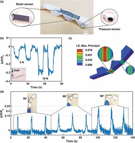
The finger in the gripper system is a typically multifunction structure with both pressure and bending sensing modality. Therefore, the whole finger was fabricated by multimaterial FDM, with a spherical shell pressure sensor and a bending sensor deployed at the tip and knuckle regions, respectively. The pressure sensor on the fingertip worked well to distinguish the force applied on the effective region, as shown in ). This detected touch signal makes it potential to determine if there is contact with actual things and thus identify the weight of gripped objects. The bending sensor is located around the joints because of the concentrated deformation according to the simulation of finger bent, as shown in ). A cable running through the soft finger was employed for bending and stretching. When the cable was pulled, two joints supported the motions of the finger. ) shows a corresponding change in the electrical signal with the bending angle of 30°, 60° and 90°, validating the effectiveness of the bending sensor. The application of the finger with two individual sensors reveals the potential of a smart structure embedded with multiple sensors to handle multitasking at a time. Such smart structures can be utilized in various intelligent systems, including soft robotics, IoT and industrial automation.
Inspired by the above applications, designers can use this workflow to create novel smart structures in soft robotics, health monitoring platforms, Internet of Things (IoT) and so on. For example, carbon-based materials, such as CB, carbon fibers (CF), and carbon nanotubes (CNT), are widely used for self-sensing concrete [Citation42,Citation43] in the field of structural health monitoring. These functional fillers share the advantages of lightweight, high chemical and thermal stability and electrical conductivity [Citation44]. By measuring the electrical resistance of the self-sensing concrete, the strain, crack, or damage of a structure can be monitored in situ.
4. Conclusions
In summary, this paper proposes a workflow to design and fabricate novel smart structures for low cost, customized properties, and high system integrity with multimaterial FDM. The produced CB/TPU filaments facilitate the sensing ability of printed parts, endowing the structures with high sensitivity to the external tension. The printability of soft filaments was examined based on the rheology characteristics and buckling criterion. By optimizing the filament feeding mechanism and print parameters, printing issues of soft filaments was relieved. Additionally, the printed smart structure embedded with flexible strain sensors possesses good sensitivity, repeatability, and stability. Such performance makes it promising to work reliably in versatile applications. The proposed workflow simplifies the fabrication of high-integrity smart structures and paves the way for more potential applications of novel smart structures. In future work, the relationship between print parameters and printed samples can be conducted systematically to analyze the influence of print parameters on the performance of the prepared functional filaments. The fatigue behavior and performance decline of carbon-based elastomer composites are also the challenges to be tackled with. In addition, filaments with higher flexibility and conductivity can be developed to print a sensor-actuator-controller combination structure to explore promising applications.
Acknowledgments
Q.G. acknowledges the support from the National Key Research and Development Program of China (No. 2020YFB1312900). Y.X. acknowledges the support from the National Natural Science Foundation of China (No. 52105261), the Guangdong Basic and Applied Basic Research Foundation (No. 2022A1515010316).
Disclosure statement
No potential conflict of interest was reported by the author(s).
Additional information
Funding
References
- Kumar KU, Boby SN, Ghoshal S, et al. An experimental study of sensor based smart structure design: a modal study. Int J Civil Eng Technol. 2017;8:862–867.
- Teng KH, Kot P, Muradov M, et al. Embedded smart antenna for non-destructive testing and evaluation (NDT&E) of moisture content and deterioration in concrete. Sensors (Basel). 2019;19(3):547.
- Li Q, Wu T, Zhao W, et al. Laser-induced corrugated graphene films for integrated multimodal sensors. ACS Appl Mater Interfaces. 2021;13(31):37433–37444.
- Sparrman B, du Pasquier C, Thomsen C, et al. Printed silicone pneumatic actuators for soft robotics. Addit Manuf. 2021;40:101860.
- Gomez EF, Wanasinghe SV, Flynn AE, et al. 3D-printed self-healing elastomers for modular soft robotics. ACS Appl Mater Interfaces. 2021;13(24):28870–28877.
- Gao Y, Yu L, Yeo JC, et al. Flexible hybrid sensors for health monitoring: materials and mechanisms to render wearability. Adv Mater. 2020;32(15):e1902133.
- Derakhshandeh H, Aghabaglou F, McCarthy A, et al. A wirelessly controlled smart bandage with 3D-printed miniaturized needle arrays. Adv Funct Mater. 2020;30(13):1905544.
- Ghosh A, Edwards DJ, Hosseini MR. Patterns and trends in Internet of Things (IoT) research: future applications in the construction industry. Eng Constr Archit Manage. 2020;28(2):457–481.
- Abdelgawad A, Yelamarthi K. Internet of things (IoT) platform for structure health monitoring. Wireless Commun Mobile Comput. 2017;2017:1–10.
- Ge Q, Li Z, Wang Z, et al. Projection micro stereolithography based 3D printing and its applications. Int J Extreme Manuf. 2020;2(2):022004.
- MacDonald E, Wicker R. Multiprocess 3D printing for increasing component functionality. Science. 2016;353(6307):aaf2093.
- Li Z, He X, Cheng J, et al. Hydrogel-elastomer-based stretchable strain sensor fabricated by a simple projection lithography method. Int J Smart Nano Mater. 2021;1–13. DOI:10.1080/19475411.2021.1952335.
- Ronca A, Rollo G, Cerruti P, et al. Selective laser sintering fabricated thermoplastic polyurethane/graphene cellular structures with tailorable properties and high strain sensitivity. Appl Sci. 2019;9(5):864.
- Ge Q, Chen Z, Cheng J, et al. 3D printing of highly stretchable hydrogel with diverse UV curable polymers. Sci Adv. 2021;7(2):eaba4261.
- Ahammed SR, Praveen AS. Direct ink writing method for manufacturing electronic circuits using multiwalled carbon nanotubes and polyvinyl alcohol composites. Mater Performance Characterization. 2020;9(1):665–674.
- Ching T, Li Y, Karyappa R, et al. Fabrication of integrated microfluidic devices by direct ink writing (DIW) 3D printing. Sens Actuators B Chem. 2019;297:126609.
- Zhang Y-F, Ge Q. A numerical framework for the design of Joule-heating circuits to thermally activate smart materials. Smart Mater Struct. 2019;28(11):115026.
- Zhang Y-F, Li Z, Li H, et al. Fractal-based stretchable circuits via electric-field-driven microscale 3D printing for localized heating of shape memory polymers in 4D printing. ACS Appl Mater Interfaces. 2021. DOI:10.1021/acsami.1c03572.
- Valentine AD, Busbee TA, Boley JW, et al. Hybrid 3D printing of soft electronics. Adv Mater. 2017;29(40):1703817.
- Goh GL, Dikshit V, Koneru R, et al. Fabrication of design-optimized multifunctional safety cage with conformal circuits for drone using hybrid 3D printing technology. Int J Adv Manuf Technol. 2022;120(3–4):2573–2586.
- O’Donnell J, Ahmadkhanlou F, and Yoon H-S, et al. All-printed smart structures: a viable option? Active Passive Smart Struct Integr Syst. 2014 9057 ;727–734.
- Ji Y, Luan C, Yao X, et al. Recent progress in 3D printing of smart structures: classification, challenges, and trends. Adv Intell Sys. 2021;2000271. DOI:10.1002/aisy.202000271.
- Han D, Lee H. Recent advances in multi-material additive manufacturing: methods and applications. Curr Opin Chem Eng. 2020;28:158–166.
- Zolfagharian A, Mahmud MP, Gharaie S, et al. 3D/4D-printed bending-type soft pneumatic actuators: fabrication, modelling, and control. Virtual Phys Prototyping. 2020;15:373–402.
- Zolfagharian A, Gharaie S, Gregory J, et al. A bioinspired compliant 3D-printed soft gripper. Soft Robot. 2021. DOI:10.1089/soro.2020.0194.
- Yarali E, Baniasadi M, Zolfagharian A, et al. Magneto‐/electro‐responsive polymers toward manufacturing, characterization, and biomedical/soft robotic applications. Appl Mater Today. 2022;26:101306.
- Tirado-Garcia I, Garcia-Gonzalez D, Garzon-Hernandez S, et al. Conductive 3D printed PLA composites: on the interplay of mechanical, electrical and thermal behaviours. Compos Struct. 2021;265:113744.
- Zhang J, Yang B, Fu F, et al. Resistivity and its anisotropy characterization of 3D-printed acrylonitrile butadiene styrene copolymer (ABS)/carbon black (CB) composites. Appl Sci. 2017;7:20.
- Yang X, Ren H, and Wu C, et al. Flexible strain sensors fabricated by fused deposition modeling-based multimaterial 3D printing with conductive polyurethane composites. 2021 27th International Conference on Mechatronics and Machine Vision in Practice (M2VIP) 26-28 November 2021 Shanghai, China. 546–551. (2021).
- Anderegg DA, Bryant HA, Ruffin DC, et al. In-situ monitoring of polymer flow temperature and pressure in extrusion based additive manufacturing. Addit Manuf. 2019;26:76–83.
- Chaunier L, Guessasma S, Belhabib S, et al. Material extrusion of plant biopolymers: opportunities & challenges for 3D printing. Addit Manuf. 2018;21:220–233.
- Awasthi P, Banerjee SS. Fused Deposition modeling of thermoplastics elastomeric materials: challenges and opportunities. Addit Manuf. 2021;102177. DOI:10.1016/j.addma.2021.102177.
- Das A, Gilmer EL, Biria S, et al. Importance of polymer rheology on material extrusion additive manufacturing: correlating process physics to print properties. ACS Appl Polym Mater. 2021;3:1218–1249.
- Venkataraman N, Rangarajan S, Matthewson M, et al. Feedstock material property–process relationships in fused deposition of ceramics (FDC). Rapid Prototyping J. 2000;6(4):244–253.
- Gilmer EL, Mansfield C, and Gardner JM, et al. Polymer-based additive manufacturing: recent developments 1315 . In: Characterization and analysis of polyetherimide: realizing practical challenges of modeling the extrusion-based additive manufacturing process Jonathan E, Seppala, Anthony P, Kotula, Chad R, Snyder. Washington, DC: ACS Publications, 2019. 69–84.
- Go J, Schiffres SN, Stevens AG, et al. Rate limits of additive manufacturing by fused filament fabrication and guidelines for high-throughput system design. Addit Manuf. 2017;16:1–11.
- Chen J, Li H, Yu Q, et al. Strain sensing behaviors of stretchable conductive polymer composites loaded with different dimensional conductive fillers. Compos Sci Technol. 2018;168:388–396.
- Park Y-L, Chen B-R, Wood RJ. Design and fabrication of soft artificial skin using embedded microchannels and liquid conductors. IEEE Sens J. 2012;12(8):2711–2718.
- Xiong Y, Yang X. A review on in-tire sensor systems for tire-road interaction studies. Sens Rev. 2018;38(2):231–238.
- Wang H, Totaro M, Beccai L. Toward perceptive soft robots: progress and challenges. Adv Sci. 2018;5(9):1800541.
- Zhang YF, Zhang N, Hingorani H, et al. Fast‐response, stiffness‐tunable soft actuator by hybrid multimaterial 3D printing. Adv Funct Mater. 2019;29:1806698.
- Tian Z, Li Y, Zheng J, et al. A state-of-the-art on self-sensing concrete: materials, fabrication and properties. Compos Part B Eng. 2019;177:107437.
- Coppola B, Di Maio L, Incarnato L, et al. Preparation and characterization of polypropylene/carbon nanotubes (PP/CNTs) nanocomposites as potential strain gauges for structural health monitoring. Nanomaterials. 2020;10(4):814.
- Han B, Ding S, Yu X. Intrinsic self-sensing concrete and structures: a review. Measurement. 2015;59:110–128.