
ABSTRACT
Liquid crystalline elastomers (LCEs) have been utilized as an important class of smart actuator materials. However, the modest actuation mechanical and robustness performances remain a challenge. Inspired by the specific structures, well mechanical properties and physico-chemical characteristics of some natural plant fibers, a composite of thiol-acrylate main-chain LCE matrix incorporated with catkin fibers is designed and developed. The catkin fibers build a network as reinforcement phase, and demonstrate effective compatibility and integration property with the matrix, their high flexibility can be adapted to the large deformational performance of LCE matrix. The prepared LCE composite demonstrates strong mechanical actuation properties. The modulus and driving force triggered by the stimuli are obviously increased. The tensile strength and fatigue failure resistant property under high loadings and repeated cycles of thermal actuation or photothermal actuation are greatly enhanced. While the stimulus response deformation rate, phase transition temperature and liquid crystal phase structure of the LCE matrix, and so on, do not weaken or change. This work promotes the LCE materials’application potential and broadens the application value of natural plant fibers.
Graphical abstract
1. Introduction
As a emerging class of polymerized smart materials with the capability of undergoing shape changes upon the application of external stimuli, liquid-crystalline elastomers (LCEs) have attracted extensive research interest in recent tens of years [Citation1–6]. LCEs are composed of a light-crosslinked elastomeric rubbery network, in which the rod or disc liquid crystal (LC) moieties are covalently bonded to the flexible polymer chain backbones. In the networks of side-chain LCEs (SC-LCEs), the mesogenic units are linked on side of flexible polymer backbones [Citation1,Citation3,Citation4]. In the networks of main-chain LCEs (MC-LCEs), the mesogenic units are directly incorporated into the backbones, and polymer chains are generally formed by interlinking the mesogens and flexible short chains which are called chain extenders [Citation1,Citation3,Citation4]. The combination of LC self-organization nature and entropic elasticity of polymer networks creates unique properties to LCE materials, such as anisotropic molecular order, active stimuli-response, reversible phase transition, reversible and large anisotropic shape change upon the imposed external stimuli, and programmable morphing performance, and so on [Citation1–6]. These fascinating properties together with the other superiorities, such as low weight, tailorable softness material, better compatibility with biologic tissues, and so on, make the LCE materials to be prospective in many applications, such as smart actuators [Citation7–18], artificial muscles [Citation19–25], soft robot [Citation26–33], and biomimetic devices [Citation34–43], and so on.
The emerging application of driving LCE materials requires sufficient mechanical properties and durability. Although the LCEs may be enough robustness at room temperature, they can be seriously weakened at high temperatures, especially at the temperatures above their driving requirement, which can lead to accidental failure. Thus they are easy to break after many times actuation in the environment of high temperatures and loads. The moderate driving forces and fatigue failure resistant ability have become a arduous challenge for the industrial application development of LCE materials. One important way of improving the polymer materials’mechanical properties is preparing polymer composites by adding other reinforcing materials into the polymer matrix [Citation44–46]. The rigid materials embedded in LCE matrices as continuous reinforcing phase may impede the materials’ deformation performances even make the LCE materials lose their actuation capability. Though some nano fillers can improve the mechanical properties when they are added into the LCE matrices [Citation47–50]. They belong to a separate reinforcing phase in LCE matrices, and the reinforcing effect may not be prominent relative to those continuous reinforcing phase materials. Fiber reinforcement materials have played a very important role in reinforced polymer composites due to their high freedom degree, agility and versatility [Citation14,Citation18,Citation51–53]. It has been reported that many natural fibers are widely used in agriculture, forestry, construction and commodity industry. They are becoming great substitutes for traditional fibers (such as glass, carbon and aramid, etc) in the research and manufacture of composites because of their light weight, carbon neutralization, recyclability, low cost, good specific strength and biodegradability [Citation54–62]. Natural fibers are divided into animal fibers, plant fibers, and mineral fibers. Some of them, due to the high flexibility, enough toughness and unique structures, can be suitable for the shape change performances of smart deformable materials, including the LCEs. Our previous work revealed that the eiderdown fibers, which are a animal fibers, could effectively improve the actuation mechanical properties and durability of LCE composites [Citation25].
In view of the more rich sources, low cost and recycling utilization requirement of some plant fibers, in this work, we study using the catkin fibers as reinforcement material to enhance the performances of LCE composites. Catkin fiber is a kind of highly flexible plant fiber with microtubule structure, low density and large surface volume ratio [Citation63–65]. The characteristics of high length/diameter ratio and natural interweaving enable them to build a continuous grid network to reinforce the host materials. A classical thiol-acrylate MC-LCE is selected as the host material, for reason that the LCEs based on thiol-acrylate systems are currently widely attracted in research and application due to scalable design of matrix networks, convenient control over the processing and property tailoring, chemical and environmental stabilities, and so on [Citation11,Citation15,Citation66–82]. In the prepared LCE composites with the thiol-acrylate MC-LCE as the matrix and the catkin fibers as the reinforcement phase (LCE/CFB composite), the hetero-phase structure between the catkin fibers and matrix demonstrated well compatibility and interface adhesion. The LCE/CFB composites showed strong driving mechanical properties, the driving blocking force and modulus were greatly enhanced by the reinforcing action of catkin fibers. Their tensile strength and fatigue failure resistant properties under repeated cycles of thermal actuation or photothermal actuation were significantly improved. While the stimulus response deformation rate was not attenuated by the addition of catkin fibers due to their flexible crimple and tensile properties, which could effectively comply with the large shape changing performance of LCE materials. The other properties of LCE/CFB composites, such as the LC phase structure and phase transition temperature, and so on, were also basically identical to the corresponding pure thiol-acrylate MC-LCE. Our work evidences the superiority and reliability of natural plant fibers in the development of LCE composites. It would promote the application potential of LCE materials, expand the recycling utilization of natural fibers, and be significant for the alternative solution of fossil materials and environmental conservation.
2. Experiment section
2.1 Materials preparation
The LC mesogenic monomer ‘4-bis-[4-(3-acryloyloxypropypropyloxy) benzoyloxy]-2-methylbenzene (RM257)’ was obtained from Yesheng Chemical Technology Co. Ltd. (Shijiazhuang, China). The crosslinker ‘Pentaerythritol tetrakis (3-mercaptopropionate) (PETMP),’ chain extender ‘2,2-(ethylenedioxy) diethanethiol (EDDET),’ photo-initiator ‘2-hydroxy-4’-(2-hydroxyethoxy)-2-methyl-propiophe (HHMP)’, and catalyst ‘dipropylamine (DPA)’ were purchased from Aladdin (Shanghai, China) Inc. The catalyst solution was prepared by diluting the DPA with toluene at a weight ratio of 1:50. The infrared (IR) absorption dye ‘Ma001-2’ was purchased from Daxing Co. Ltd. (Shenzhen, China).
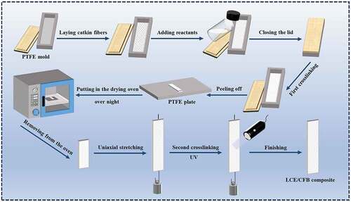
The preparation protocol of the catkin fibers incorporated thiol-acrylate MC-LCE composite (LCE/CFB) is illustrated in . The catkin fibers of 20 mg was evenly pre-laid at the bottom of a rectangular polytetrafluoroethylene mold, whose dimensions were 60 mm, 15 mm and 15 mm in length, width and height, respectively. The precursor reactant mixture was prepared by dissolving 1 g (1.699 mmol) RM257, 0.225 g (1.234 mmol) EDDET, 0.055 g (0.112 mmol) PETMP and 8 mg HHMP (photo-initiator) in 1 ml toluene, adding 180 µl catalyst solution. The mixture was poured into the mold. The mold was first implemented by ultrasonication for 15 seconds to eliminate micro-bubbles in the solution, then set in environment of 28°C for 10 hours to achieve the first step crosslinking. In this stage, a swollen gel elastomer containing toluene was generated. It was transferred out of the mold and dried in a vacuum drying oven at 65°C and 508 mmHg overnight to let the contained toluene evaporated, then uniaxially stretched by a 20 g load for 12 hours to be a stable length. The stretched elastomer was irradiated by the 365 nm UV light for 9 minutes to complete the second step crosslinking, and the film shaped LCE/CFB composite with 0.95 wt% of catkin fiber content was obtained. The blank thiol-acrylate MC-LCE was also prepared through the above procedure but without the addition of catkin fibers. The preparations of the dye doped LCE/CFB composite and dye doped blank thiol-acrylate MC-LCE with 0.1 wt% of dye content were consistent with those of the LCE/CFB composite and blank thiol-acrylate MC-LCE, respectively, but moderate amount of dye ‘Ma001-2’ was added into the above precursor reactant mixture.
Scheme 1. Illustration of the experimental protocol for preparing the LCE/CFB composite.
2.2 Characterization methods
The mesomorphic properties were measured by using polarizing optical microscopy (POM) (SMZ1500, Nikon Instruments) and 2D X-ray scattering (2D-WAXS), which was a Bruker/Siemens Hi-Star 2D X-ray Diffractometer. The differential scanning calorimetry (DSC) (Q100, TA Instruments, DE) was used to investigate the phase transformation at a temperature variation rate of 5°C⋅min−1. The scanning electron microscopy (SEM; Zeiss LEO 1530, Thornwood, NY, U.S.A) was used to observe the inner heterophase structure of LCE/CFB material. A dynamic mechanical analyzer (Q800 DMA, TA Instruments, U.S.A) was employed to measure the mechanical moduli. The contractile forces or strains performed by LCE materials upon the thermal or light stimulus were measured by using a universal material mechanical analyzer equipped with a thermostat cabinet (CMT-10, LG Company, Jinan, China). In the thermal stimulus, the examined sample was settled inside the thermostat cabinet, which regulated the heating/cooling processes. In the light stimulus, the examined sample was directly irradiated by an IR light source whose irradiation intensity could be tuned by turning the knob assembled on it. The temperature variations of material surfaces in response to light irradiation were measured in situ by using a multilogger thermometer with a detector of 2 mm in length and 100 mm in diameter. The contractile strains were measured in isoforce mode, the two ends of the sample were clamped with a constant tension load. The contractile forces were measured in isostrain mode, the two ends of the sample were clamped and elongated by a constant tension strain. The tensile strengths at different temperatures, and the fatigue failure resistant performances under passively drawing/restoring cycles of LCE materials at different temperatures were measured also by using the universal material mechanical analyzer. The examined sample was settled inside the thermostat cabinet, which regulated the temperature setting. The experiment environment temperature was about 26°C.
3. Results and discussion
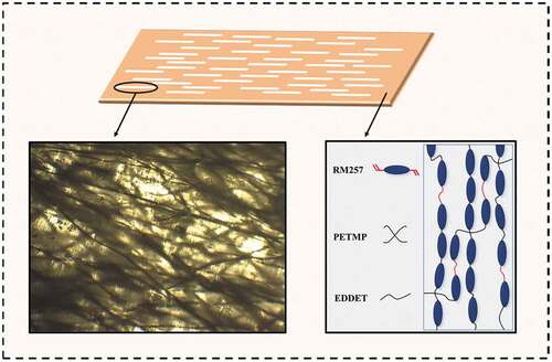
The synthesis of matrix network of thiol-acrylate MC-LCE was via a sol-gel processed two-step Michael addition and polymerization reaction coupled with a stretching process between the two steps (TAMAP) [Citation69,Citation70]. As illustrated by , the precursor reactants included the monomers of mesogen (RM257), chain extender (EDDET), and crosslinker (PETMP). In the first step, the terminal vinyl bonds of acrylate groups in mesogenic molecules reacted with the -SH bonds of crosslinker molecules and chain extender molecules in the presence of catalyst for ‘click’ reaction of Michael addition to achieve polyaddition polymerization and crosslinking, and generate a polydomain network. Then an external stress was applied to establish a monodomain network with mesogen alignment along the stress direction. In the second step, the crosslinking of excess acrylate groups was completed by photo initiated polymerization to fix the alignment of mesogens and monodomain structure. The preparation protocol of our LCE/CFB composites were based on above TAMAP route of thiol-acrylate MC-LCE network synthesis, as illustrated in and described in experiment section. ) presents a micrograph image of the catkin fibers. It shows that the catkin fibers had a circular circumferential shape with about 5 to 10 μm of diameters, and very large ratio of length to diameter, which could endow them a high ratio of surface to volume. While the catkin fibers naturally formed loose interweaving network, which could let them to easily construct continuous reinforcement phase evenly distributed in the host materials. ) exhibits a SEM picture of the sliced section of LCE/CFB. It shows that the catkin fibers and LCE matrix compactly bonded together, the adhesion of interface between them was tight.
Scheme 2. Illustration of the precursor reactant molecules and the synthesis of thiol-acrylate MC-LCE networks through TAMAP route.
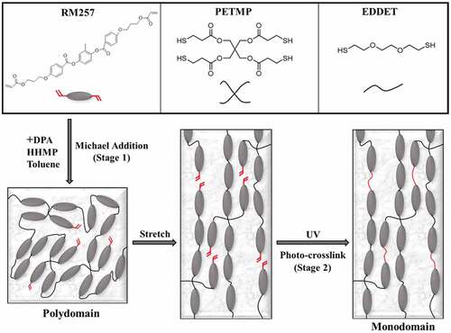
Figure 1. (a) A optical microscope image of the catkin fibers. (b) A SEM image of the cross section of the LCE/CFB composite. The embedded catkin fibers are pointed by the arrows.
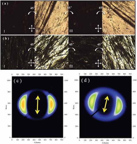
The images of POM observation of the blank thiol-acrylate MC-LCE and LCE/CFB composite, as respectively, shown in , evaluated the anisotropic mesogen alignment effect by measuring the transmittance of polarized light through the crossed polarizer and analyzer with a measuring sample between them. The highest transmittance could be demonstrated when their stretch directions inclined at an angle of ±45° relative to the analyzer or polarizer (). The transmittance became minimum when their stretch directions were paralleled to the polarizer () or analyzer (). POM observation confirmed a monodomain matrix structure in them, and the mesogens were axially aligned along the stretch directions. 2D-WAXS measured with the normal directions of material surface being parallel to the incident beam of X-ray was implemented to further research the mesomorphic properties. The 2D-WAXS patterns of the blank LCE and LCE/CFB composite were, respectively, presented in . They all demonstrated the azimuthal intensity maxima at wide-angle reflection which implied the nematic LC phase structure in LCE matrices [Citation1]. Moreover, the locations of azimuthal intensity maxima were orthogonal to the material stretch directions, thus further confirmed the axial mesogen alignment along the stretch directions, which was caused by the stress-induced orientation effect.
Figure 2. (a, b) The POM images of blank thiol-acrylate MC-LCE (a) and LCE/CFB composite (b), inserted crossed pointers illustrate the polarization directions of the horizontal analyzer and vertical polarizer. (a-I, b-I) The polarizer is paralleled to the stretch directions. (a-II, b-II) The stretch directions are at −45° angle of inclination to the polarizer. (a-III, b-III) The analyzer is paralleled to the stretch directions. (a-IV, b-IV) The stretch directions are at −45° angle of inclination to the analyzer. (c, d) The 2D-WAXS patterns of the blank thiol-acrylate MC-LCE (c) and LCE/CFB composite (d), inserted arrows point the stretch directions.
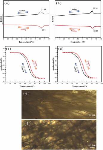
, respectively, provides the DSC data curves of the blank thiol-acrylate MC-LCE and LCE/CFB composite. Each shows a distinct peak in the heating or cooling scan, corresponding to the nematic-isotropic or isotropic-nematic phase transition. The nematic-isotropic transition temperatures (Tni) demonstrated in heating scan curves of the blank thiol-acrylate MC-LCE and LCE/CFB were, respectively, 82.71°C and 82.23°C. These results revealed that they both had enantiotropic nematic phase and that their phase transition temperatures were approximately equal to each other. The prepared blank thiol-acrylate MC-LCE and LCE/CFB composite performed thermal induced reversible deformation behavior. , respectively, provides the data plots of axial strain versus temperature variation of them upon the heating/cooling process, which were measured in isoforce mode with a constant axial tension of 40 kPa. Upon the heating process, their axial contraction strains increased with the increase of temperature, finally reached a stable maximum value of above sixty percent when the temperature was above Tni. During the cooling process, axial contraction strains decreased with the decrease of temperature, finally returned to initial value. This deformation was caused by the nematic order change of LCE matrices. The change of mesogen alignment degree, which was triggered by temperature variation, changed the nematic order, and hence triggered the transformation between the nematic phase and isotropic state when the LCE materials were heated above or cooled below the Tni, resulted in spontaneous contraction or elongation along alignment directions of LCE materials [Citation3,Citation4,Citation6]. It is indicated by inspecting that the performance of thermal driven shape changing of LCE/CFB composite was basically consistent with that of the blank thiol-acrylate MC-LCE, and almost not influenced by the incorporation of catkin fibers. This should be owed to the high flexibility of catkin fibers which derived from their microtubule structure and the high amorphous cellulose content in them [Citation64,Citation65]. The catkin fibers could agilely cooperated with the shape change of LCE matrix through the flexible crimple and extension behavior. The micrographs presented by show the states of the catkin fibers embedded in LCE matrix at 25°C and at 90°C, respectively. The catkin fibers demonstrated a certain ordered extension pattern at 25°C, which should be caused by the external stress stretching in the preparation process of LCE/CFB composite. At 90°C which was above the Tni and the LCE/CFB composite fully contracted, the embedded catkin fibers crimped to be disordered state, and thus effectively avoided the impediment on material deformation.
Figure 3. (a, b) DSC data curves upon heating and cooling scans of the blank thiol-acrylate MC-LCE (a) and LCE/CFB composite (b). (c, d) The Plots of the axial strain of blank thiol-acrylate MC-LCE (c) and LCE/CFB composite (d) versus temperature variation upon a cycle of heating and cooling, in isoforce (40 kPa) mode. (e, f) Microscope images of the LCE/CFB composite at 25°C (e) and at 90°C (f).
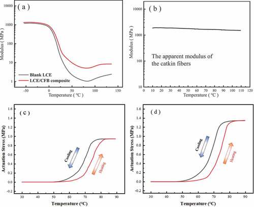
The data plots of the Young modulus versus temperature variation of these two LCE materials, as given in ), indicated that their Young moduli gradually decreased with the increase of temperature due to the thermal softening effect of polymers, and dropped to minimal values at the temperatures around the Tni for reason of the occurrence of phase transition in matrix. But the decreasing rate of Young modulus of LCE/CFB was obviously lower than that of blank thiol-acrylate MC-LCE, and hence the LCE/CFB composite constantly kept higher Young modulus compared to the blank thiol-acrylate MC-LCE. At the temperatures around Tni, the Young modulus of the former was about 5 times as high as that of the latter, as shown in ). One reason of this modulus variation difference lied in the thermal stable mechanical properties of catkin fibers. The apparent Young modulus versus temperature variation of the catkin fiber bundles was measured, and the corresponding data plot is shown in ). It indicates that the apparent Young modulus of the catkin fiber bundles did not obviously change at the temperature range from 10°C to 110°C. The second reason lied in the large contacting interface and tight interfacial adhesion between the catkin fibers and LCE matrix. The tight interfacial adhesion could be led by the molecular attraction between the – OH groups on cellulose molecules contained in catkin fibers [Citation64,Citation65] and the C = O groups in LCE network. The large and tight bonding interface between the catkin fibers and LCE matrix could effectively hindered the dislocation motions in matrix and ensure a high stress transfer efficiency. These two factors made the LCE/CFB composite kept higher Young modulus compared to the blank thiol-acrylate MC-LCE at different temperatures. The higher modulus of LCE/CFB composite increased its elastic contraction capability. Under the condition of forced length fixation, the LCE materials demonstrated thermal induced reversible change of contractile actuating force. , respectively, show the data plots of axial contractile stresses produced by blank thiol-acrylate MC-LCE and LCE/CFB with temperature change during the heating/cooling process, which were measured in isostrain mode with a constant tension strain of 0.1%. Upon the heating process, their contractile actuation stresses gradually increased until to be maximum, which was the blocking actuation stress, when they were heated above Tni. Upon the cooling process, the contractile actuation stresses decreased and finally returned to initial value. It is indicated by inspecting ) that the blocking actuation stress of LCE/CFB, which was about 1.35 Mpa, was obviously higher than that of blank thiol-acrylate MC-LCE, which was about 0.93 Mpa. This should be caused by the improved modulus property endued by catkin fiber reinforcement. The mechanical modulus of LCE/CFB was greatly higher than that of blank thiol-acrylate MC-LCE at Tni, at which the thermal-induced contractile actuation fully occurred, thus LCE/CFB composite demonstrated a greatly higher blocking actuation stress compared to the blank thiol-acrylate MC-LCE. Our experiment exhibited that when the catkin fiber content was below 0.8 wt%, the modulus and blocking actuation stress of LCE/CFB composites began to decrease. When the catkin fiber content was above 1.3 wt%, the maximum thermal induced contraction strain of LCE/CFB composites began to decrease. The modulus and maximum thermal induced contraction strain of LCE/CFB composites had no appreciable distinction in the catkin fiber content from 0.8 wt% to 1.2 wt%. We used 0.95 wt% of catkin fiber content as the reasonable content.
Figure 4. (a) The data curves of Young moduli versus temperature variation of the blank thiol-acrylate MC-LCE and LCE/CFB composite respective. (b) The data curves of apparent Young modulus versus temperature variation of the catkin fiber bundles. (c, d) The plots of the actuation stresses of the blank thiol-acrylate MC-LCE (c) and LCE/CFB composite (d) versus temperature variation upon a cycle of heating and cooling, in isostrain (0.1%) mode.
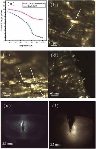
) shows the diagram of the measured tensile strengths at different temperatures of the blank thiol-acrylate MC-LCE and LCE/CFB. The tensile strengths decreased with temperature increasing, and decreased steeply near the Tni for reason that the LCE polymer chains lost the axial orientation, resulted in their axial strengthening effect being remarkably declined. The decreasing rate of the tensile strength of LCE/CFB composite were also obviously lower than that of the blank thiol-acrylate MC-LCE. Thus the LCE/CFB composite constantly kept higher tensile strength compared to the blank thiol-acrylate MC-LCE. At the temperatures around Tni, the tensile strength of the former was about 3 times as high as that of the latter, as shown in ). It is significant that the LCE materials can maintain a high tensile strength at the temperatures around the Tni because they need often undergoing such temperature environment to perform fully mechanical actuation. Experiment results indicated that the catkin fibers incorporated into LCE matrix greatly enhanced the material’s tensile strength. One mechanism was that the catkin fibers effectively resisted the crack expansion. ), an optical micrograph of LCE/CFB tested by tension failure, demonstrates that the catkin fibers restricted the tiny cracks and made them not further grew. The mini cracks occurred in LCE matrix inclined to propagate due to the stress action. When they encountered the catkin fibers, the crack planes had to bifurcate to bypass the catkin fibers. The crack deflection effect required much more energy dissipation, and thus the propagations of the cracks often halted [Citation45,Citation46]. In addition, if the crack planes bypassed the fibers, the bridging effect of catkin fibers across the tiny cracks also could retard the further growth of cracks, as shown in ). Another mechanism lied in the strong interfacial adhesion between the matrix and catkin fibers, as evidenced by ), which is an optical micrograph of LCE/CFB tested by tensile break. It indicates that there was no obvious pulling-out phenomenon of catkin fibers on the fracture plane. The strong interfacial adhesion could effectively enhance the stress transfer efficiency between the hetero phases and dissipate energy along the interface, while was beneficial for the resistance of crack propagation. For the blank thiol-acrylate MC-LCE, the mini cracks occurred at any location, such as the middle or side, could unrestrictedly grow to become large cracks, resulted in the material being easily fractured, as evidenced by ), which were the optical micrographs of the blank thiol-acrylate MC-LCE tested by tension failure.
Figure 5. (a) The tensile strengths versus temperature of the blank thiol-acrylate MC-LCE and the LCE/CFB composite. (b, c, d) Optical micrograph images of the LCE/CFB composites which were tested by tension failure: (b) The arrow pointing part is the tiny crack in matrix whose expansion was restricted by the catkin fibers. (c) The arrow pointing parts are the tiny cracks in matrix whose expansion was hindered by the bridging effect of catkin fibers. (d) The fractured section shows the pulling out state of the catkin fibers. (e, f) The optical micrograph images of blank thiol-acrylate MC-LCEs which were tested by tension failure: The cracks in the middle (e) or side (f) of the matrix unrestrictedly expanded.
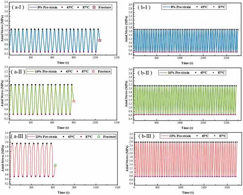
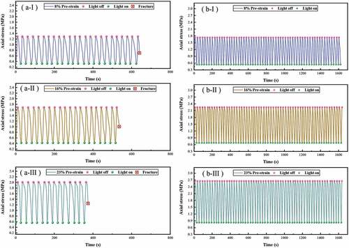
The fatigue failure resistant performances of blank thiol-acrylate MC-LCE and LCE/CFB upon the thermal actuation of repeated heating/cooling cycles were investigated. , respectively, provides the data plots of axial strains varying with time of them measured in isoforce mode under repeated temperature cycles between 45°C and 87°C. The two LCE materials all performed repeated axial strain variation of contraction/restoration under repeated cycles of heating and cooling process. The blank thiol-acrylate MC-LCE demonstrated that its repeated contraction/restoration cycle times, at which the fracture did not occurred, decreased with the increase of the constant tension load. It fractured after 20 times of repeated contraction/restoration cycle under the constant tension load of 0.36 MPa (). It fractured after 16 times of repeated contraction/restoration cycle under the constant tension load of 0.54 MPa (). It fractured after 10 times of repeated contraction/restoration cycle under the constant tension load of 0.68 MPa (). However, under the same constant tension loads, the LCE/CFB composite performed stable contraction/restoration variation without the occurring of fracture after 60 times of repeated heating and cooling process, as shown in , respectively. give the measurement plots of the axial contractile stresses varying with time of the two LCE materials measured in isostrain mode under repeated temperature cycles between 45°C and 87°C. The two LCE materials all demonstrated cyclic variation of contractile stresses upon repeated cycles of heating and cooling process. The blank thiol-acrylate MC-LCE showed that its repeated cycle times of contractile stress variation without the occurring of fracture decreased with the increase of the constant pre-elongation strain. Under the constant axial pre-elongated strains of 8%, 16% or 23%, its stable cyclic variation times of contractile stress was 23 times, 17 times and 11 times, respectively, as shown in , respectively. While the LCE/CFB composite demonstrated stable cyclic variation of axial contractile stress after 60 times of repeated cycles of heating and cooling process with the same constant pre-elongated strains, as exhibited in , respectively. These experiment results indicated that the LCE/CFB composite had a greatly better fatigue failure resistant performance under repeated thermal actuation compared to blank thiol-acrylate MC-LCE.
Figure 6. Upon repeated heating/cooling cycles and in isoforce mode, the axial strains versus time of the blank thiol-acrylate MC-LCE (a) and LCE/CFB composite (b) with different tension loads.
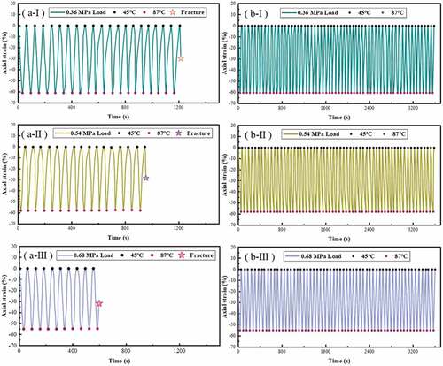
Figure 7. Upon repeated heating/cooling cycles and in isostrain mode, the actuation stresses versus time of the blank thiol-acrylate MC-LCE (a) and LCE/CFB composite (b) with different pre-elongated strains.
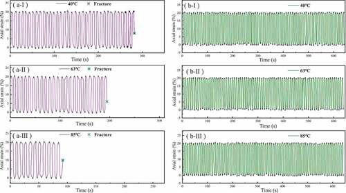
The fatigue failure resistant performances of blank thiol-acrylate MC-LCE and LCE/CFB upon repeated cycles of passively axial drawing/restoring at different temperature were investigated. , respectively, provides the measured data plots of axial strains varying with time of them which were repeatedly drawn and restored with the tension strain range being from 0 to 20%, and at 40°C, 63°C and 85°C, respectively. At 40°C, the blank thiol-acrylate MC-LCE fractured after about 35 times of repeated drawing/restoring cycles (). At 63°C, the blank thiol-acrylate MC-LCE fractured after about 24 times of repeated drawing/restoring cycles (). At 85°C, the blank thiol-acrylate MC-LCE fractured after about 11 times of repeated drawing/restoring cycles (). However, at the same temperatures, the LCE/CFB composite did not fracture after 80 times of repeated drawing/restoring cycles, as exhibited in , respectively. The experiment results evidenced a superior anti-fatigue performance of LCE/CFB composite under being repeatedly drawn.
Figure 8. Upon repeated cycles of passively drawing/restoring, the axial strains versus time of the blank thiol-acrylate MC-LCE (a) and LCE/CFB composite (b) at different temperature.
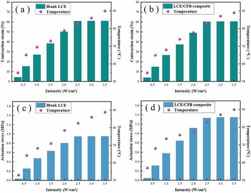
We further investigated the actuation mechanical properties and fatigue failure resistant performances of the LCE materials by using the photo stimulus. The blank thiol-acrylate MC-LCE and LCE/CFB composite were doped by a little amount of IR absorption dye ‘Ma001-2,’ so that the dye could absorb the light irradiation and converted them into heating effect to actuate the LCE materials. Diagrams shown in present the axial contraction strains and the achieved stable temperatures on materials in response to different IR irradiation intensities of the dye doped blank thiol-acrylate MC-LCE and dye doped LCE/CFB composite, respectively, which were measured in isoforce mode with a constant tension load of 60 kPa. It demonstrates that the contraction strains of the two LCE materials increased as the irradiation intensity increased for reason that a higher irradiation intensity created a higher temperature on the materials, as shown in . When the irradiation intensity was above 2.5 W/cm2, the contraction strains did not further increase because the achieved temperatures on materials in response to the IR irradiation were already above the Tni. The maximum contraction strains of the two LCE materials were above sixty percent, which was basically equal to the thermal derived maximum contraction strains, as shown in . The diagrams shown in , respectively, present the axial contractile stresses and the achieved stable temperatures of the two LCE materials in response to different IR irradiation intensities, which were measured in isostrain mode with a constant tension strain of 0.1%. It indicates that the contractile stresses increased as the irradiation intensity increased for reason that a higher irradiation intensity created a higher temperature on the materials, as shown in . When the irradiation intensity was above 2.5 W/cm2, the achieved temperatures were above the Tni, the contractile stresses arrived the blocking actuation stresses and did not continuously change. It is indicated from the showing of that the blocking actuation stresses of the dye doped blank thiol-acrylate MC-LCE and dye doped LCE/CFB composite triggered by IR irradiation were about 0.94 MPa and 1.36 MPa, respectively, which were basically equal to their respective thermal triggered blocking actuation stresses, as shown in .
Figure 9. (a, b) The axial contraction strains and the achieved stable temperatures of the dye doped blank thiol-acrylate MC-LCE (a) and dye doped LCE/CFB composite (b) versus IR intensity, in isoforce (60 kPa) mode. (c, d) The actuation stresses and the achieved stable temperatures of the dye doped blank thiol-acrylate MC-LCE (c) and dye doped LCE/CFB composite (d) versus IR intensity, in isostrain (0.1%) mode.
provide the experiment results of fatigue failure resistant performances under repeated photothermal actuation of the dye doped blank thiol-acrylate MC-LCE and dye doped LCE/CFB composite. , respectively, exhibits the plots of axial strains varying with time of the two LCE materials measured in isoforce mode under repeated switching on/off cycles of IR with irradiation intensity of 3.5 W/cm2. The two LCE materials all performed repeated axial strain variation of contraction/restoration under repeated on/off IR irradiation. Under the constant tension load of 0.36 MPa, 0.54 MPa and 0.68 MPa, respectively, the dye doped blank thiol-acrylate MC-LCE fractured after 24 times (), 19 times () and 11 times () of contraction/restoration cycle, respectively. While the dye doped LCE/CFB composite performed stable contraction/restoration variation without the occurring of fracture after 60 times of repeated on/off IR irradiation, as respectively, exhibited in . provide the measurement plots of axial contractile stresses varying with time of the two LCE materials measured in isostrain mode under repeated switching on/off cycles of IR with irradiation intensity of 3.5 W/cm2. They all demonstrated cyclic variation of axial contractile stresses under repeated on/off IR irradiation. It is indicated from the showing of that under the constant axial pre-elongated strains of 8%, 16% and 23%, respectively, the stable cyclic variation times of contractile stress of the dye doped blank thiol-acrylate MC-LCE was 24 times, 20 times and 14 times, respectively. While the LCE/CFB composite demonstrated stable cyclic variation of axial contractile stress after 60 times of repeated on/off IR irradiation with the same constant pre-elongated strains, as exhibited in ), respectively. Experiment results evidenced that the fatigue failure resistant performance upon the repeated photothermal actuation of LCE/CFB was also greatly superior to the blank thiol-acrylate MC-LCE, thus revealed a well reliability and durability of plant fibers reinforced LCE composites.
Figure 10. Upon repeated switching on/off cycles of IR with irradiation intensity of 3.5 W/cm2, and in isoforce mode, the axial strains versus time of dye doped blank thiol-acrylate MC-LCE (a) and dye doped LCE/CFB composite (b) with different tension loads.
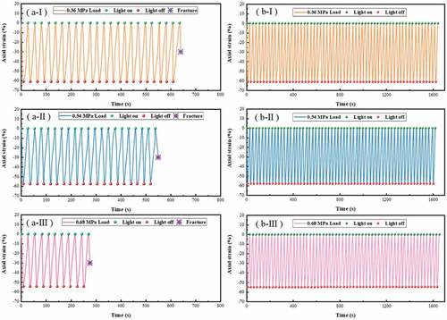
Figure 11. Upon repeated switching on/off cycles of IR with irradiation intensity of 3.5 W/cm2, and in in isostrain mode, the actuation stresses versus time of dye doped blank thiol-acrylate MC-LCE (a) and dye doped LCE/CFB composite (b) with different pre-elongated strains.
4. Conclusions
For several tens of years, the modest mechanical properties and robustness of LCE materials have seriously impeded their industrial applications. They are related to the using cost, using occasions, safety and service life of the materials, and thus have become a key issue of LCE research field. Some natural fibers can be used for the reinforcement of stimuli-responsive polymer deformable materials owing to their advantages, such as low weight, unique structures, high flexibility and valuable mechanical properties. Thiol-acrylate LCEs are widely attracted in the application research at current. Their synthesis process can also be suitable for the convenient fabrication of large-sized LCE composites with flexile continuous fibers as reinforcement phase.
Our previous work used the eiderdown fibers to enhance the mechanical actuation performances of LCE materials [Citation25]. But the conformation of eiderdown fibers is down cluster structure, that is the fiber clusters grow on the down stones [Citation83]. Such structure may not be benefit for their even dispersity in polymer matrices, and thus limit the ultimate reinforcement effect. Moreover, in viewing that some plant fibers, such as catkin fibers, and so on, have more rich sources and and urgent recycling utilization requirement for reason they may often create environmental disturbance every year. In this work, we study using the catkin fibers as reinforcement material to enhance the performances of LCE composites.
The catkin fibers were used as the reinforcement phase to prepare LCE composite with a thiol-acrylate MC-LCE matrix. The catkin fibers built reinforcing phase network through the LCE matrix, demonstrated tight interfacial adhesion and well compatibility with the matrix, and effectively enhanced the driving mechanical properties and material robustness. The blocking actuation force and mechanical modulus were significantly increased. The tensile strength and fatigue failure resistant properties under repeated cycles of thermal actuation or photothermal actuation were also significantly improved. While the stimulus response deformation rate was not attenuated by the addition of catkin fibers due to their flexible crimple and tensile properties. The phase transition temperature and LC phase structure, and so on, were also basically not influenced by the addition of catkin fibers due to their well thermal stability and chemical stability. Our method can be expected to develop more plant fiber incorporated LCE composites with excellent driving performance, reliability and durability, and promote the application development of LCEs as artificial muscles and smart actuators, and so on. Our work is conducive to expand the recycling utilization of natural plant materials, and thus is significant for the environmental conservation and the saving of fossil materials’ consumption.
Supplemental Material
Download MS Word (21.7 MB)Acknowledgments
This research work was supported by the Natural Science Foundation of Heilongjiang Province of China (Grant No. LH2020E106), and the Open Research Fund Program of Institute of regulatory science (Grant No. CRS-2020-01), Beijing Technology and Business University. We thank the researchers in the Chemistry Department of Heilongjiang University and the researchers in Harbin Institute of Technology for academic and technical communications and support.
Disclosure statement
No potential conflict of interest was reported by the author(s).
Supplementary material
Supplemental data for this article can be accessed online at https://doi.org/10.1080/19475411.2022.2133188
Additional information
Funding
References
- De Jeu WH. Liquid crystal elastomers: materials and applications. Aachen Germany: Aachen University; 2012.
- Yu H. Photoresponsive liquid crystalline block copolymers: from photonics to nanotechnology. Prog Polym Sci. 2014;39(4):781–815.
- Kularatne RS, Kim H, Boothby HJM, et al. Liquid crystal elastomer actuators: synthesis, alignment, and applications. J Polym Sci Part B Polym Phy. 2017;55(2017):395–411.
- Ula SW, Traugutt NA, Volpe RH, et al. Liquid crystal elastomers: an introduction and review of emerging technologies. Liq Cryst Rev. 2018;6(1):78–107.
- Pilz da Cunha M, Debije MG, Schenning APHJ. Bioinspired light-driven soft robots based on liquid crystal polymers. Chem Soc Rev. 2020;49(18):6568–6578.
- Wang QE, Niu H, Wang HY, et al. Carbon nanotubes modified nanocomposites based on liquid crystalline elastomers. Mol Cryst Liq Cryst. 2021;732(1):11–49.
- Liu L, Wang M, Guo L-X, et al. Aggregation-induced emission luminogen-functionalized liquid crystal elastomer soft actuators. Macromolecules. 2018;51:4516–4524.
- Saed MO, Ambulo CP, Kim H, et al. Molecularly‐engineered, 4d‐printed liquid crystal elastomer actuators. Adv Funct Mater. 2018;29(3):1806412.
- Chen Q, Li Y, Yang Y, et al. Durable liquid-crystalline vitrimer actuators. Chem Sci. 2019;10(10):3025–3030.
- Zuo B, Wang M, Lin BP, et al. Visible and infrared three-wavelength modulated multi-directional actuators. Nat Commun. 2019;10(1):4539.
- He Q, Wang Z, Wang Y, et al. Recyclable and self-repairable fluid-driven liquid crystal elastomer actuator. ACS Appl Mater Interfaces. 2020;12(31):35464–35474.
- Li Y, Liu Y, Luo D. Polarization dependent light‐driven liquid crystal elastomer actuators based on photothermal effect. Adv Opt Mater. 2020;9:2001861.1–2001861.9.
- Xu J, Zhao N, Qin B, et al. Optical wavelength selective photoactuation of nanometal-doped liquid crystalline elastomers by using surface plasmon resonance. ACS Appl Mater Interfaces. 2021;13(37):44833–44843.
- Song T, Lei H, Clancy AJ, et al. Supramolecular hydrogen bond enables Kapton nanofibers to reinforce liquid-crystalline polymers for light-fueled flight. Nano Energy. 2021;87:106207.
- Wang YP, Sun JH, Liao W, et al. Liquid crystal elastomer twist fibers toward rotating microengines. Adv Mater. 2022;34(9):2107840.
- Liu Z, Bisoyi HK, Huang Y, et al. Thermo- and mechanochromic camouflage and self-healing in biomimetic soft actuators based on liquid crystal elastomers. Angew Chem Int Ed. 2022;61:e202115755.
- Zhao T, Zhang Y, Fan Y, et al. Light-modulated liquid crystal elastomer actuator with multimodal shape morphing and multifunction. J Mater Chem C. 2022;10(10):3796–3803.
- Hu J, Yu M, Wang M, et al. Design, regulation, and applications of soft actuators based on liquid-crystalline polymers and their composites. ACS Appl Mater Interfaces. 2022;14(11):12951–12963.
- Tian H, Wang Z, Chen Y, et al. Polydopamine-coated main- chain liquid crystal elastomer as optically driven artificial muscle. ACS Appl Mater Interfaces. 2018;10(9):8307–8316.
- Kim H, Lee JA, Ambulo CP, et al. Intelligently actuating liquid crystal elastomer-carbon nanotube composites. Adv Funct Mater. 2019;29(48):1905063.
- Lu H-F, Wang M, Chen X-M, et al. Interpenetrating liquid-crystal polyurethane/polyacrylate elastomer with ultrastrong mechanical property. J Am Chem Soc. 2019;141(36):14364–14369.
- Liu H, Tian H, Shao J, et al. An electrically actuated soft artificial muscle based on a high-performance flexible electrothermal film and liquid-crystal elastomer. ACS Appl Mater Interfaces. 2020;12(50):56338–56349.
- Chen C, Liu Y, He X, et al. Multiresponse shape-memory nanocomposite with a reversible cycle for powerful artificial muscles. Chem Mater. 2021;33(3):987–997.
- Lee JH, Bae J, Hwang JH, et al. Robust and reprocessable artificial muscles based on liquid crystal elastomers with dynamic thiourea bonds. Adv Funct Mater. 2022;32(13):2110360.
- Zhao N, Wang X, Yao L, et al. Actuation performance of a liquid crystalline elastomer composite reinforced by eiderdown fibers. Soft Matter. 2022;18(6):1264–1274.
- Qian X, Chen Q, Yang Y, et al. Untethered recyclable tubular actuators with versatile locomotion for soft continuum robots. Adv Mater. 2018;30(29):1801103.
- Zeng H, Wasylczyk P, Wiersma DS, et al. Light robots: bridging the gap between microrobotics and photomechanics in soft materials. Adv Mater. 2018;30(24):1703554.
- He QG, Wang ZJ, Wang Y, et al. Electrically controlled liquid crystal elastomer-based soft tubular actuator with multimodal actuation. Sci Adv. 2019;5(10):eaax5746.
- Shen C, Lan R, Huang R, et al. Photochemically and photothermally controllable liquid crystalline network and soft walkers. ACS App Mater Interfaces. 2021;13(2):3221–3227.
- Li Y, Yu HB, Yu K, et al. Reconfigurable three-dimensional mesotructures of spatially programmed liquid crystal elastomers and their ferromagnetic composites. Adv Funct Mater. 2021;31(23):2100338.
- Zhang J, Guo Y, Hu W, et al. Liquid crystal elastomer-based magnetic composite films for reconfigurable shape-morphing soft miniature machines. Adv Mater. 2021;33(8):2006191.
- Apsite I, Salehi S, Ionov L. Materials for smart soft actuator systems. Chem Rev. 2022;122(1):1349–1415.
- Yu Z, Wang Y, Zheng J, et al. Fast-response bioinspired near-infrared light-driven soft robot based on two-stage deformation. ACS Appl Mater Interfaces. 2022;14(14):16649–16657.
- Lv JA, Liu YY, Wei J, et al. Photocontrol of fluid slugs in liquid crystal polymer microactuators. Nature. 2016;537(7619):179.
- Palagi S, Mark AG, Reigh SY, et al. Structured light enables biomimetic swimming and versatile locomotion of photoresponsive soft microrobots. Nat Mater. 2016;15(6):647.
- Wang M, Lin BP, Yang H. A plant tendril mimic soft actuator with phototunable bending and chiral twisting motion modes. Nat Commun. 2016;7(1):13981.
- Shahsavan H, Salili SM, Jakli A, et al. Thermally active liquid crystal network gripper mimicking the self-peeling of gecko toe pads. Adv Mater. 2017;29(3):1604021.
- Zuo B, Wang M, Lin B-P, et al. Photomodulated tricolor-changing artificial flowers. Chem Mater. 2018;30(21):8079–8088.
- Ferrantini C, Pioner JM, Martella D, et al. Development of light-responsive liquid crystalline elastomers to assist cardiac contraction. Circ Res. 2019;124(8):e44–e54.
- Shaha RK, Merkel DR, Anderson MP, et al. Biocompatible liquid-crystal elastomers mimic the intervertebral disc. J Mech Behav Biomed Mater. 2020;107:103757.
- Hussain M, Jull EIL, Mandle RJ, et al. Liquid crystal elastomers for biological applications. Nanomaterials. 2021;11(3):813.
- Liu Z, Bisoyi HK, Huang Y, et al. An artificial light-harvesting system with controllable efficiency enabled by an annulene-based anisotropic fluid. Angew Chem Int Ed. 2022;61:e202115755.
- Wang YP, Liao W, Sun JH, et al. Bioinspired construction of artificial cardiac muscles based on liquid crystal elastomer fibers. Adv Mater Technol. 2022;7(1):2100934.
- Robert MJ. Mechanics of composite materials. New York U.S.A: McGraw-Hill Book Company; 1975.
- Ku H, Wang H, Pattarachaiyakoop N, et al. A review on the tensile properties of natural fiber reinforced polymer composites. Compos Part B-Eng. 2011;42(4):856–873.
- Siddique A, Abid S, Shafiq F, et al. Mode I fracture toughness of fiber-reinforced polymer composites: a review. J Ind Text. 2021;50(8):1165–1192.
- Ji Y, Marshall JE, Terentjev EM. Nanoparticle-liquid crystalline elastomer composites. Polymers. 2012;4(1):316–340.
- Cresta V, Romano G, Kolpak A, et al. Nanostructured composites based on liquid-crystalline elastomers. Polymers. 2018;10:773.
- Guin T, Kowalski BA, Rao R, et al. Electrical control of shape in voxelated liquid crystalline polymer nanocomposites. ACS Appl Mater Interfaces. 2018;10:1187–1194.
- Liu JQ, Gao YC, Wang HH, et al. Shaping and locomotion of soft robots using filament actuators made from liquid crystal elastomer-carbon nanotube composites. Adv Intell Syst. 2020;2(6):1900163.
- Liu YJ, Du HY, Liu LW, et al. Shape memory polymers and their composites in aerospace applications: a review. Smart Mater Struct. 2014;23(2):023001.
- Liu TZ, Zhou TY, Yao YT, et al. Stimulus methods of multi-functional shape memory polymer nanocomposites: a review. Compos A Appl S. 2017;100:20–30.
- Xia YL, He Y, Zhang FH, et al. A review of shape memory polymers and composites: mechanisms, materials, and applications. Adv Mater. 2020;33(6):2000713.
- Kabir MM, Wang H, Lau KT, et al. Chemical treatments on plant-based natural fibre reinforced polymer composites: an overview. Compos Part B-Eng. 2012;43(7):2883–2892.
- Fortea-Verdejo M, Bumbaris E, Burgstaller C, et al. Plant fibre-reinforced polymers: where do we stand in terms of tensile properties? Int Mater Rev. 2017;62(8):441–464.
- Mohit H, Arul Mozhi Selvan V. A comprehensive review on surface modification, structure interface and bonding mechanism of plant cellulose fiber reinforced polymer based composites. Compos Interfaces. 2018;25(5–7):629–667.
- Sun Z. Hyperbranched polymers in modifying natural plant fibers and their applications in polymer matrix composites-a review. J Agric Food Chem. 2019;67(32):8715–8724.
- Kenned JJ, Sankaranarayanasamy K, Kumar CS. Chemical, biological, and nanoclay treatments for natural plant fiber-reinforced polymer composites: a review. Polym Polym Compos. 2020;29:1011–1038.
- Sippach T, Dahy H, Uhlig K, et al. Structural optimization through biomimetic-inspired material-specific application of plant-based natural fiber-reinforced polymer composites (nfrp) for future sustainable lightweight architecture. Polymers. 2020;12(12):3048.
- Lee CH, Khalina A, Lee SH. Importance of interfacial adhesion condition on characterization of plant-fiber-reinforced polymer composites: a review. Polymers (Basel). 2021;13(3):438.
- Mohit H, Mavinkere Rangappa S, Siengchin S, et al. A comprehensive review on performance and machinability of plant fiber polymer composites. Polym Composite. 2021;43(1):608–623.
- Wong D, Anwar M, Debnath S, et al. A review: recent development of natural fiber-reinforced polymer nanocomposites. Jom. 2021;73(8):2504–2515.
- Zhang XX, Li ZQ, Yu Y, et al. Characterizations of poplar catkin fibers and their potential for enzymatic hydrolysis. J Wood Sci. 2018;64(4):458–462.
- Wu Y, Wu XY, Shi TL, et al. The microstructure and mechanical properties of poplar catkin fibers evaluated by atomic force microscope (AFM) and nanoindentation. Forests. 2019;10(11):938.
- Yuan YA, Xiao YY, Jia ZX, et al. Facile synthesis of flexible hollow conductive polyaniline composite fibers from willow catkins. J Nat Fibers. 2020;17(10):1479–1487.
- Hoyle CE, Bowman CN. Thiol-ene click chemistry. Angew Chem Int Ed. 2010;49:1540–1573.
- Martella D, Parmeggiani C, Wiersma DS, et al. The first thiol-yne click chemistry approach for the preparation of liquid crystalline elastomers. J Mater Chem C. 2015;3(34):9003–9010.
- Ware TH, Perry ZP, Middleton CM, et al. Programmable liquid crystal elastomers prepared by thiol-ene photopolymerization. ACS Macro Letters. 2015;4(9):942–946.
- Yakacki CM, Saed M, Nair DP, et al. Tailorable and programmable liquid-crystalline elastomers using a two-stage thiol-acrylate reaction. RSC Adv. 2015;5(25):18997–19001.
- Saed MO, Torbati AH, Nair DP, et al. Synthesis of programmable main-chain liquid-crystalline elastomers using a two-stage thiol-acrylate reaction. J Vis Exp. 2016;107:e53546.
- Torbati AH, Mather PT. A hydrogel-forming liquid crystalline elastomer exhibiting soft shape memory. J Polym Sci Part B. 2016;54(1):38–52.
- Saed MO, Torbati AH, Starr CA, et al. Thiol-acrylate main-chain liquid-crystalline elastomers with tunable thermomechanical properties and actuation strain. J Polym Sci Part B: Polym Phys. 2017;55(2):157–168.
- Saed MO, Volpe RH, Traugutt NA, et al. High strain actuation liquid crystal elastomers via modulation of mesophase structure. Soft Matter. 2017;13(41):7537–7547.
- Xia Y, Zhang X, Yang S. Instant locking of molecular ordering in liquid crystal elastomers by oxygen-mediated thiol-acrylate click reactions. Angew Chem Int Ed. 2018;57(20):5665–5668.
- Barnes M, Verduzco R. Direct shape programming of liquid crystal elastomers. Soft Matter. 2019;15(5):870–879.
- Cho EH, Luu K, Park SY. Mechano-actuated light-responsive main-chain liquid crystal elastomers. Macromolecules. 2021;54(12):5397–5409.
- Hebner TS, Fowler HE, Herbert KM, et al. Polymer network structure, properties, and formation of liquid crystalline elastomers prepared via thiol-acrylate chain transfer reactions. Macromolecules. 2021;54(23):11074–11082.
- Li Y, Luo C, Yu K, et al. Remotely controlled, reversible, on-demand assembly and reconfiguration of 3d mesostructures via liquid crystal elastomer platforms. ACS Appl Mater Interfaces. 2021;13(7):8929–8939.
- Ma B, Xu C, Cui L, et al. Magnetic printing of liquid metal for perceptive soft actuators with embodied intelligence. ACS Appl Mater Interfaces. 2021;13:5574–5582.
- Martinez A, Clement A, Gao J, et al. Thermomechanically active electrodes power work-dense soft actuators. Soft Matter. 2021;17(6):1521–1529.
- Ni B, Liu G, Zhang M, et al. Customizable sophisticated three-dimensional shape changes of large-size liquid crystal elastomer actuators. ACS Appl Mater Interfaces. 2021;13(45):54439–54446.
- Li Y, Liu T, Ambrogi V, et al. Liquid crystalline elastomers based on click chemistry. ACS Appl Mater Interfaces. 2022;14(13):14842–14858.
- D’alba L, Carlsen TH, Asgeirsson A, et al. Contributions of feather microstructure to eider down insulation properties. J Avian Biol. 2017;48(8):1150–1157.