
 ?Mathematical formulae have been encoded as MathML and are displayed in this HTML version using MathJax in order to improve their display. Uncheck the box to turn MathJax off. This feature requires Javascript. Click on a formula to zoom.
ABSTRACT
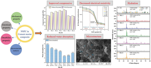
In material science, converting waste into nanomaterials by green technologies highlights the interest in producing sustainable carbon nanomaterial (SCN). This study first-ever utilized tyre-char as a Nano-Structure Pyrolytic Carbon (NSPC) to develop electrically conductive composites. Unlike other carbon nanomaterials, the efficiency of NSPC particle as an SCN in developing electrically conductive composites was investigated in terms of dispersion, mechanical, water absorption, electrical resistivity, and microstructure. The results of sedimentation and zeta potential (−19 mV) showed the excellent dispersion of NSPC particle in water with the combined effect of superplasticizer and ultrasonication. The compressive (40.37%) and flexural strength (10.76%) than that of plain cement mortar composite (CMC) is achieved with 2 wt.% and 1.5 wt.% of NSPC particle, respectively. The water absorption rate and volume of permeable voids were reduced, exhibiting less agglomerations. The percolation zone of AC and DC resistivity of NSPC composite ranges between 1 and 2 wt.%, and the established percolation threshold is at 2 wt.%. XRD analysis showed C-S-H formation consistently increased with curing age, and HR-SEM with EDAX analysis exhibits the dense microstructure and well-distributed NSPC particle at the nanoscale. These experimental outcomes significantly enhanced the reliability and provided a framework for tailoring NSPC particle as SCN for developing electrically conductive composite.
GRAPHICAL ABSTRACT
1. Introduction
After the invention of cement 200 years ago in 1824, cement-based materials have become essential for promoting infrastructure construction due to their inherent strength properties [Citation1]. However, it is associated with some significant drawbacks such as uncontrollable cracks at nano-scale (inefficient space interlocking) [Citation2], low tensile strength [Citation2,Citation3], poor electrical conductivity capacity [Citation4] and so on. In addition, the performance standard of traditional cement-based materials is primitive to meet the need for advanced building materials [Citation5]. Therefore, developing a new intelligent composite material is more important to eliminate the hindered progress to attain sustainable development and swift innovation in infrastructure construction. However, the evolution of Engineering Cementitious Composite (ECC), High Performance Cement Composite (HPCC), and High Strength Cement Composite (HSCC) are accessible. The advancement in electrically conductive composite will be a key direction for developing a new form of smart and sustainable construction [Citation6,Citation7].
The research on electrically conductive composites has focused on the conductivity properties by incorporating the various functional fillers into cement matrix. Several efforts were made to improve the electrical conductivity by infusing various kinds and sizes of functional fillers, including steel fiber [Citation8], steel slag [Citation9], copper slag [Citation10], carbon fiber [Citation11], metal particles or hybrid additive [Citation8,Citation12,Citation13]. However, the carbon-based functional filler has taken center stage for the manufacture of electrically conductive composite compared to other fillers [Citation13–16]. The excellent conductive nature of carbon nanomaterials is envisioned as an effective filler to enhance the electrical conductivity in cement composites to achieve self-sensing properties [Citation17]. Electrically based multifunctional composites have broad applications in civil engineering, transportation, energy, and habitat development. It provides fundamental material for enabling ‘digitization and intelligence’ to achieve smart construction for structural health monitoring [Citation18,Citation19]. Concurrently, the domain of nanotechnology is globally recognized for its excellent performance in the construction sector. Over the years, the research on nanomaterial studies of cement composites has received substantial emphasis owing to its potential to revolutionize the development of electrically conductive composites [Citation20,Citation21]. Besides the ongoing research, nanomaterials play a vital role in exceeding the working properties of cement composites [Citation22,Citation23] and enhancing their mechanical, thermal, durability, and electrical properties [Citation24–26]. With the series of research, various types of carbon-based nanomaterials were extensively employed to modify the performance of cement-based composites, including graphite powder [Citation27,Citation28], graphene [Citation29,Citation30], carbon black [Citation31,Citation32], carbon nanotubes (CNT) [Citation33,Citation34], and carbon nanofiber [Citation35]. The structural characteristic effect of these nanomaterials in cement-based composites leads to four major effects (size, surface, quantum, and interfacial effect), which assist in the development of smart and intelligent cement composites that are used for various advanced applications [Citation15,Citation20,Citation28]. Despite the excellence of using nanomaterials in the construction industry, the practical application of nanomaterials indulges in significant drawbacks such as uneconomical, hazardous nature due to their nanoparticle size, and increased complications, etc. This has prompted the purpose of introducing sustainable nanomaterial instead of commercial nanomaterial beyond its conflicting results. Moreover, pursuing sustainable development by utilizing industrial waste material and its by-product as a sustainable nanomaterial has been on the rise, as indicates the role of nanomaterial in the sustainable development of construction industry [Citation21]. Among them, utilizing end-of-life tyres, which constitute almost 2–3% of total global waste, will be an ultimate choice to produce SCN.
Figure 1. Role of nanomaterial in sustainable development of construction industry.

According to Material Recycling Association of India (MRAI), the end-of-life tyres are generated over 100 million per year. These resources are indeed embedded with a rich carbon content collectively valuable for advanced developments. Therefore, a sustainable and indispensable pyrolysis treatment, which is one of the green and renewable methods to recycle end-of-life tyres, is employed for recovering SCN [Citation36]. In general, pyrolysis is the process of heating end-of-life tyres at temperatures ranging between 500°C and 550°C that yields tyre char, oil, gas, and steel wire, having a mass balance of 37.45%, 39.62%, 13.32%, and 9.95%, respectively. The NSPC particles yielded through pyrolysis treatment containing rich carbon origin of 80–90% is the theme of this study. Tyre-char is an emerging and inexpensive source of nano-carbon particles with excellent mechanical resilience, high surface area to volume, and favorable electrical conductivity [Citation37,Citation38]. Furthermore, the physicochemical characteristic of tyre char has attracted the researcher interest toward the construction material for utilization as a concrete additive, phase change material (PCM), and to process bitumen as binder material. In this regard, Sardar et al. utilized pyrolytic tyre char as an additive to develop high strength fire-resistant concrete. The authors experimentally proved that the tyre char has the ability to reduce the spalling of concrete at high temperatures (800°C). Further, the authors also optimized the addition of tyre char at 1% to achieve better residual performance at elevated temperatures [Citation39]. Meanwhile, Paul et al. carried out possible characterization techniques on pyrolytic carbon (tyre-char) and proposed it as an alternative filler to commercial carbon black [Citation40]. Khalid et al. and Mahmood et al. experimented on nano-structure tyre char having more than 90% carbon content in cementitious composites. The influence of nano-sized tyre char reduced the porosity of cement composite, which significantly improved the fracture toughness (48.8%) and compressive strength (43.1%) [Citation41,Citation42]. On the other hand, Mahmood et al. optimized the carbon tyre-char to 0.5 wt.% for enhancing the electromagnetic interference shielding by 24.2 db [Citation41]. Ryms et al. performed sustainable investigations on the utilization of pyrolytic carbon in cement composites to develop PCM carriers. The authors demonstrated that the addition of pyrolytic carbon to cement mortar enhanced the heat accumulation and capacity for energy saving. In time, the developed PCM carrier was used for energy-saving construction exhibiting better thermal comfort [Citation43]. Additionally, incorporating tyre char into bitumen improved the electrothermal [Citation44] and rheological properties. However, few research works revealed that the tyre char (>2.5 wt.%) as a partial replacement of cement decreases the mechanical strength due to minimum quantity of cement and weak interface [Citation45,Citation46]. Inherently, the hydrophobic nature and strong surface inertia of tyre char inhibit the hydration processes which slow down the acceleration of C2S/C3S process in the cement composites. Therefore, emphasizing the tyre char particle as an additive to cement is appropriate to minimize the adverse effects. Despite the pros and cons, the relationship between dispersing NSPC particle and their beneficial impact on electrical properties has not been identified. Further, the effective use of a secondary binder is also crucial for assisting the hydration process to enhance the interface of NSPC composites [Citation47–49].
Carbon nanomaterial with high specific surface area tends to agglomerate due to gravitate effect. The agglomerations of carbon nanomaterials have poor cohesion and resistance to external forces. Consequently, cementitious composites are susceptible to many defects which greatly reduce the electrical, mechanical, and durable properties [Citation50]. To uniformly disperse the carbon nanoparticles in cementitious matrix, the preferred approaches from many studies include ultrasonication process, solvents, mineral, and chemical additives for surface modification. The efficient dispersion of carbon nanomaterials is achieved by adopting at least two of the above dispersing methods. The duration of ultrasonication is the crucial factor that regulates the efficient dispersion of carbon nanomaterial. Accordingly, Chaipanich et al. [Citation51] and Nochaiya et al. [Citation52] dispersed CNT in water for 10 and 5 min of ultrasonication, respectively, and improved the mechanical properties of cement composites. Du and Pang increased the sonication time up to 2 h and reduced the rate of sedimentation, indicating the better dispersion of carbon nanomaterials [Citation53]. Meanwhile, the longer sonication time (2 to 5 h) reduces the conductivity of CNT composites after the change of conduction state [Citation54]. Notably, the ultrasonication duration is dependent on the water-to-binder ratio and concentration of nanocarbon filler. Furthermore, the application of chemical admixture can improve the dispersion of carbon nanomaterial. Collins et al. and Chuah et al. investigated on various admixtures and observed that polycarboxylate is a promising chemical admixture for the dispersion of carbon nanomaterial [Citation55,Citation56].
Furthermore, Supplementary Cementitious Materials (SCM) is typically used to enhance the strength and durable properties of the cement composites [Citation57]. In particular, including Silica Fume (SF) that is less than 1 µm in size as a partial substitution to cement exhibits pozzolanic characteristics and regulates the cement hydration process [Citation58,Citation59]. Moreover, the contribution of SF as a mineral additive to cement possesses the capacity for the dispersion of nanomaterials reducing van der wall forces between fillers and pore size due to its filling effect [Citation60,Citation61]. Kim et al. reported that utilizing a high dosage of SF can reduce the electrical resistivity of cement composites [Citation61]. Nevertheless, Li et al. showed that overdose of SF can lead to reduction in compressive strength [Citation62]. Meanwhile, numerous studies have highlighted the potential of incorporating 10% of SF, which could serve in separating the nanoparticles mechanically without compromising compressive strength [Citation62–64]. It could be deduced that the SF (10%) is susceptible to disperse NSPC particle in cement mortar without reducing compressive strength and electrical conductivity. Moreover, the hybrid dispersion method reduced the size of nanoparticle agglomeration, removed air bubbles, and obtained well-dispersed carbon nanoparticle suspension [Citation65]. The studies with hybrid dispersion achieved dense microstructure and improved mechanical properties. As a consequence of these studies, the hybrid dispersion methods combining ultrasonication, mineral and chemical admixture will be an efficient alternative to disperse NSPC particle in water and cement matrix.
Although tyre char and SF have been employed as a supplementary material in advanced fields, the research on the role of NSPC particle as an SCN and SF as a secondary binder having dispersing capabilities on the electrical and engineering properties of cement composites is not yet reported. Therefore, in this study, the physicochemical characterization of NSPC using various techniques is performed and indicating these particles as SCN for integrating effectively into cement matrix will be the primary objective. Further, a new physico-mechanical method is proposed for the dispersion of NSPC particle, and the dispersion state is evaluated by sedimentation process and zeta potential tests. The enhanced effect of NSPC particle concentration on the behavior of cement mortar containing 10% SF in terms of flowability, mechanical strength (compressive, flexural, and split-tensile), water absorption, and electrical properties were investigated. The High Resolution–Scanning Electron Microscope with Energy Dispersive X-ray Analysis (HR-SEM with EDAX) and X-Ray powder Diffraction analysis (XRD) were performed to observe the surface morphology and different hydration phases present in the NSPC composites, respectively. Finally, this study could provide complete information on the design and developing the electrically conductive composites using NSPC particle.
2. Research significance
The purpose of this research is to lay the foundation for the systematic utilization of NSPC particle as SCN to aid in the development of electrically conductive composites. At first, the intent of this study involves determining the multifunctional property of NSPC particle and their superior dispersion in water. The central aspect is to identify the impact of NSPC particle on mechanical strength, electrical conductivity, and microstructure properties. Therefore, this research focused on optimizing the concentration of NSPC particle in CMC using compressive, flexural, split-tensile, water absorption, dry-density, permeable voids, electrical resistivity, and microstructure development. Later, the cost analysis of NSPC composites was estimated by calculating the Economy Index (EI) value. Eventually, this research will provide valuable information about the application of NSPC particle as SCN in cementitious matrices for developing economically sustainable electrically conductive composites.
3. Material properties and design method
3.1. Raw materials
In this study, cement mortar was adopted as a matrix. The raw materials used to prepare CMC were Ordinary Portland Cement (OPC) of Grade 53 (accordance with IS 12,269: 2013), produced by Chettinad Cement Co. Ltd, India. SF obtained from Astraa chemicals, Chennai, India (conforming to IS 15,388: 2003) was incorporated as a partial replacement to cement as a secondary binder material. SF is used to improve the dispersion of nanomaterials and mechanically separate the agglomerated particles in the cement matrix [Citation60]. The river sand was constituted as fine aggregate in this experiment with particle size less than 1 mm. The physical properties (accordance with IS 4031 and IS 2386) and chemical composition (XRF spectroscopy) of cement, SF, and river sand are represented in , respectively. represents the particle size distribution of cement and sand (accordance with IS 2386 (part 1) − 1963) that are well graded for casting mortar. A polycarboxylate ether-based MasterGlenium SKY superplasticizer with a density of 1.10 g/cm3 provided by Master Builder Solutions, India, was adopted as a chemical admixture to promote the non-covalent method of dispersing nanomaterials and facilitate workability of CMC. Ethanol as a solvent was used to enhance the dispersion of nanomaterial through the surface modification method. The whole experimental work was carried out using tap water available in the laboratory.
Figure 2. Particle size distribution of cement and sand.
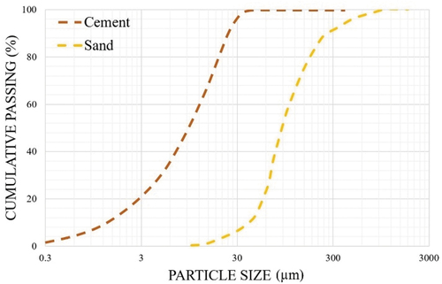
Table 1. Physical properties of cement, SF, and sand.
Table 2. Chemical composition of raw materials using XRF analysis.
3.2. Nanomaterial
The NSPC particle shown in was acquired after the pyrolysis treatment of end-of-life tyres from GS Pyro Enterprise Pvt. Ltd., India. Further, the NSPC particle was dried in the oven for 2 h at 60°C to remove the moisture content and ground through a planetary ball milling process (200 rpm/3 h) to reduce the size of nanomaterial below 100 nm. They represent a potential carbon source that can be used as an SCN in the CMC to develop electrically conductive composites [Citation66]. The physical properties and chemical composition are determined using BET model (Brunauer-Emmett-Teller), BJH model (Barrett-Joyner-Halenda) and XRF, respectively, which are summarized in . Further, the pH value, oil absorption (DBP), and loss on ignition (LOI) were also determined according to IS 877:1989, IS 33:1992, and IS1612:1976, respectively.
Figure 3. Photograph and morphology of NSPC particle.
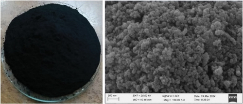
Table 3. Physical properties of NSPC particle.
Table 4. Chemical composition of NSPC particle.
3.3. Characterization of NSPC
Evaluating the physicochemical properties of nanomaterials is important before incorporating them into cement composites. Thus, various characterization techniques are subjected to examine the nano properties of NSPC particle to enable their viability as a sustainable nanomaterial. In this regard, the desired particle size (<100 nm) is achieved through planetary ball milling (200rpm, 3 h, 10 mm Zirconia balls). Subsequently, SEM analysis (TESCAN VEGA3, 30kV, SE mode) was employed to determine the particle size, morphology, size distribution, and aggregation state of NSPC particle. The presence of Carbon (C) content along with Hydrogen (H), Nitrogen (N), Sulphur (S), and Oxygen (O) is calculated using CHNSO elemental analyzer (5mgChem90s) having purge and trap technology with helium gas as a carrier flowing at the rate of 213–223 ml/min. Moreover, the surface texture, atomic composition, and distribution of elements were identified by HR-SEM with EDAX (QUANTA FEG 200F, 20kV, SE mode). The crystallite size, crystallographic structure, and crystallinity were observed using XRD (RIGAKU Smartlab 3 kW, 200 V, 50/60 Hz, 30ϕ 30A). The analysis was carried out using CuKά radiation and recorded by ‘2θ’ continuous diffraction scan ranging from 5°- 80° with a ramp of 0.02° (2θ). The optical conductivity (σ opt) and bandgap energy (eV) were determined to confirm the electronic state of NSPC particle using Ultra Violet-Visible spectroscopy (UV-VIS, DRA Evolution 300) in the wavelength ranging from 200 to 800 nm. The thermal stability, phase change, and maximum weight loss as a function of temperature were analyzed using a thermogravimetric analyzer (TGA, STA 3700, hHitachi) in which samples were heated to 750°C under nitrogen atmosphere at a rate of 20°C/min. To identify the structural defects at an atomic level, the bands and bonds were characterized using FT-Raman spectroscopy (FTR, Bruker RFS 27 Multi RAM) in the wave number ranging between 4000 and 50 cm−1. Furthermore, the hydrophobicity and surface tension of NSPC particle were calculated using Water Contact Angle (WCA) measurements (Kyowa DMe-211Plus) by adopting the sessile-drop technique with tangent measuring method and Owens-Wendt-Rabel-Kaelble (OWRK) model, respectively.
3.4. Dispersion process
In this work, four physico-mechanical dispersion methods were proposed, as shown in for assessing the effective dispersion of NSPC particle in water. The dosage of water and NSPC particle was calculated based on water to binder (w/b) ratio of 0.45. The dispersion state of NSPC particle in four different solutions was analyzed through sedimentation and zeta potential test to select well-dispersed suspension for subsequent cement mortar mixes. In sedimentation test, all the samples were visually observed from 0 min to 24 h for dispersion effectiveness, and the precipitated samples were pictured after 0 min, 15 min, 30 min, 1 h, 2 h, 4 h, 8 h, and 24 h. Meanwhile, zeta potential (ζ) exhibits the degree of electrostatic repulsion among adjacent particles when nanomaterials are dispersed in water [Citation67]. Therefore, it possesses the potential (ζ) between liquid medium and nanoparticle, where the zeta potential value is used to assess the dispersion effect of water and superplasticizer [Citation68]. The zeta potential values were measured using Malvern Zetasizer, which is operated with the electrophoretic light scattering principle, and the higher zeta values indicate the superior dispersion of nanomaterials in solution because of better electrostatic repulsion between the particles and vice-versa.
Table 5. Different physicomechanical methods and mix proportion for the dispersion of NSPC particle.
3.5. Mix proportion, sample preparation, and specimen details
Conductive materials are the most essential factor that affects the electrical properties of cement composites. Accordingly, this study adopted a single variable principle by only varying the dosage of NSPC particle. Simultaneously, SF by 10% of the weight of cement is incorporated as a secondary binder for the dispersion of nanoparticles [Citation69]. Therefore, NSPC particle was added at a concentration of 0.5%, 1%, 1.5%, 2%, 2.5%, and 3% weight of binder (cement and SF) to tailor the conductivity of the CMC. The binder to sand mix ratio is retained as 1:2. Further, the w/b ratio of 0.45 and the superplasticizer of 0.6% by weight of binder are sustained for all the conducted mixtures to study the lone effect of NSPC dosage on developing electrically conductive composites. summarizes the detailed mix proportion of one control (CC) and six modified mortar (M1-M6) mixtures investigated in this research.
Table 6. Mix proportion for plain CMC and NSPC composites.
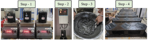
In this study, the first admixing technique was adopted for the preparation of CMC containing NSPC particle to design electrically conductive composites. depicts the schematic illustration of the fabricating procedure for NSPC composites. Initially, the raw materials and nanomaterials were weighed according to the design mix proportion. Firstly, the water and superplasticizer were mixed in a beaker for 20 s. At the same time, NSPC particles and ethanol at a 1:10 ratio were mixed mechanically in another beaker for 1 min. The ethanol solution with dissolved NSPC particle is added to the aqueous solution and stirred for 4 h using a magnetic stirrer (REMI, 1MLH and 2MLH) at 400 rpm to evaporate the ethanol from the suspension. Secondly, the NSPC suspension is subjected to ultrasonication (RIVOTEK, Probe Sonicator) for 1 h at 50% amplitude for uniform dispersion. The different set of intervals during ultrasonication (i.e. 15 s cycle and 30-min work break) were adopted to avoid the foaming and overheating of suspension. The effectiveness of dispersed NSPC particle in an aqueous solution for all the concentrations was evaluated by analyzing the absorption spectra using UV-VIS spectroscopy, as depicted in . Meanwhile, the weighed cement, SF, and sand were dry-mixed for 3 min. Thirdly, the acquired NSPC dispersed solution is then poured into the dry cement mixture and mixed until homogeneous. The mixing procedure of cement mortar followed the IS: 2550–1981. After mixing, the prepared fresh cement composite was transferred into oiled molds and vibrated to eliminate air voids. Subsequently, to measure the electrical properties of CMC, two steel meshes with 2 mm × 2 mm mesh size and thickness of 1 mm were embedded into some fresh samples immediately after casting. The configuration of electrodes is shown in . The casted samples were demolded after 1 day (24 ± 2 h) and cured under standard room conditions (Figure S1). The specimen details including size and shape of the samples and the total number of samples for each type of test are explained in .
Figure 4. Schematic representation of preparing electrically conductive composite using NSPC particle.
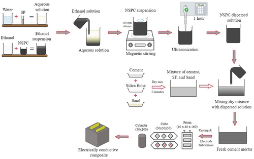
Figure 5. UV-Vis absorption spectra of dispersed NSPC particle in aqueous solution.
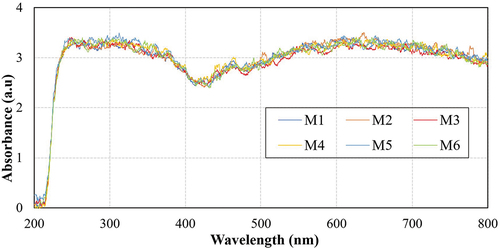
Figure 6. Electrode configurations a) fabricated 50mm3 cubes with two electrodes b) side view c) front view.
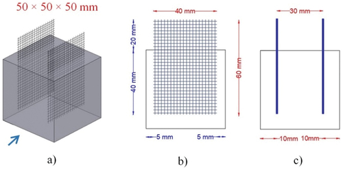
Table 7. Specimen details of CMC for different test methods.
4. Testing methods
4.1. Fresh properties
The flowability of the freshly prepared mortar is determined by measuring the diffusion diameter in a flow table. The flowability test was performed in accordance with ASTM C1437. The fresh NSPC composite is transferred into a truncated cone mold (50 mm height, top opening 70 mm, and bottom opening 100 mm), which is positioned in the center of the flow table. After removing the mold, the flow table was subjected to 25 times tamping in 15 s with 0.6 s for each tamp. For each mix, the average flowability is calculated with at least four measured diffusion diameters in different directions.
4.2. Experimental set-up for mechanical properties
The mechanical properties of CMC samples up to 90 days were evaluated to determine the impact of NSPC particle (six different concentration levels) on their compression, flexural, and split-tensile strength following ASTM C 109, ASTM C 348–08, and ASTM C496/C496M–11, respectively. shows the dimensions of fabricated specimens and different curing ages proposed for mechanical property tests. The compression testing machine (SHIMADZU, Concreto 2000X) with 2000kN capacity was used for the compression strength test and the universal testing machine (SHIMADZU, AG-X plus) with 50kN capacity was used for flexural and split-tensile strength tests (Figure S2). The flexural strength was determined by 3-point bending with lower support spacing between 100 mm. The loading rate was set to 0.15N/mm2/second for compression and 0.06N/mm2/second for flexural and split-tensile tests. Three independent tests were carried out on replicated samples for each batch to obtain average strength of the NSPC composites.
4.3. Water absorption, permeable voids, and dry density
The purpose of attaining the reliability of electrically conductive composites, a water absorption test was carried out on every mix as it is firmly related to electrical resistivity. At the same time, incorporating nano fillers can alter the pore arrangement of the cement mortar. Consequently, the volume of permeable voids (%) affects the dry density of mortar. Therefore, the water absorption, volume of permeable pore space, and dry bulk density of the CMC samples were calculated after 90 days of hydration using the pieces of cylinder (100 mm × 50 mm in size) having a volume of 392.7 cm3, according to ASTM C642.
4.4. Experimental set-up for electrical properties
The electrical properties were determined by measuring the electrical resistance of a 50 mm3 cube containing NSPC particle at curing ages of 1 day, 3 days, 7 days, 14 days, 28 days, 56 days, & 90 days. All the specimens were wiped off and dried in an oven for 24 h at temperature of 100°C prior to the test. This process could eliminate the free water in the samples and evade the polarization effect on the measurement of electrical resistance to achieve true resistivity. Inherently, the electrical resistance is measured using either four electrode or two electrode method, in which electrodes are embedded in the composites. Although four electrode pattern is successful in eliminating the polarization effect and contact resistance, it is a complicated method for electrode installation and electrical resistance measurement [Citation70]. Conversely, two electrode method is relatively simple in cross-sectional area, electrode arrangement, signal measurement, and offers consistent measurement [Citation71]. Further, two probes is a competent layout for measuring high resistivity where the passing of current (I) and measuring of voltage (V) are between the same two probes. However, the two probe method comprised with contact resistance [Citation70,Citation72]. Besides, two electrode method can yield sufficiently good measurements when the built-in resistance is significantly greater than the contact resistance at probes [Citation73].
Therefore, the challenging two electrode method was employed to measure Direct Current (DC) resistance using Keithley 2200 digital multimeter and Alternating Current (AC) resistance using Agilent 34461A digital multimeter at 100 Hz, 1 kHz, 10 kHz, & 100 kHz frequencies. The experimental setup for measuring DC and AC electrical resistance and its circuit diagram is shown in respectively. The relationship between electrical resistance (AC and DC) and electrical resistivity of the NSPC composite was investigated in accordance with the previous studies [Citation74] as described in Equationequations (1)(1)
(1) and (Equation2
(2)
(2) ).
Figure 7. Experimental setup for measuring electrical resistance a) DC method b) AC method c) schematic illustration of DC & AC circuit.
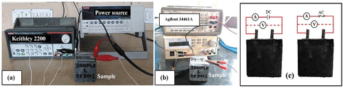
Where ‘V’ is the voltage (volt), ‘I’ is the current (ampere), is the electrical resistivity (Ω cm), ‘R’ is the electrical resistance (Ω), ‘L’ is the distance between the two electrodes (cm), and ‘A’ is the cross-section area of embedded electrodes (cm2).
4.5. Microstructure properties
The diffractogram pattern for the NSPC composite samples at curing ages of 1 day, 7 days, 28 days, & 90 days was measured to study the apparent change in the hydration products. Hence, the diffractogram pattern for composites on 3 days, 14 days, and 56 days are excluded. The RIGAKU smartlab instrument with a continuous ‘2θ’ scan ranging from 5° to 80° is used to determine the XRD pattern. The XRD quantitative analysis was performed using X’Pert Highscore plus software to determine the various hydration phases. The test samples were immersed in ethanol to terminate the hydration reaction and dried in a vacuum oven for 3 h. Further, the samples were grounded to fine powder and collected for XRD analysis. On the other hand, the HR-SEM-EDAX (CARL ZEISS EVO 10 with Lab6 Emission) analysis was performed on all mixes to observe the surface morphology, micro-nano structure, and elemental distribution of NSPC composite. The samples for HR-SEM analysis were collected as small fragments from the inner core of specimens after 90 days of compressive strength, and the analysis was carried out using SE imaging mode.
5. Results and discussion
5.1. Characterization of NSPC particle
The present research has employed all the potential characterization techniques to evaluate the physicochemical interaction of the NSPC particles obtained from pyrolyzed waste tyre. The parameters and properties such as particle size, shape, morphology, specific surface area, elemental composition, crystallite size, polymorph crystallinity, bandgap energy, thermal and optical conductivities, bonding, hydrophobic behavior, and surface tension were determined. (All the equations used to validate the nano properties of NSPC particles are detailed in the Sections 3.1 to 3.5 of supplementary data).
The mean diameter of the NSPC particles was reduced from 112.8 nm to 55.6 nm using an efficient planetary ball milling process. In addition, the particle size distribution using statistical analysis and non-linear fitting Gauss curve using Levenberg Marquardt iteration was utilized to confirm the reduction in particle size after the ball milling process (Figure S3-S4). The SEM analysis displayed that the NSPC particle is spherical, having a well-defined 2D structure with an interconnected network and uniform surface morphology (). CHNSO test confirmed the presence of high carbon content (71.28%) (Table S1). Nevertheless, the significant sulfur content (3.3%) and a small portion of hydrogen content (1.25%) indicate the solid residual part and less reactive to form C-H bonds, respectively. This was further corroborated by the EDX data, which also evidenced high carbon content (>90%). The determined molecular mass of the NSPC particles was found to be 180.64 g/mol, while its molecular formula is C102H21NS2O25, which could be used to tailor the properties of the NSPC particles. The relative quantities of C, O, Si, S, and Zn estimated by elemental analysis using EDX are given in . The EDX spectrum evidenced that NSPC particle is carbon governed materials possessing approximately 90% of carbon atoms, which is higher than graphene oxide [Citation75]. Meanwhile, the distribution of S (1.43%) and Zn (0.94%) confirms the ZnS that formed due to sulfidation [Citation76] and the distribution of oxygen (6.43%) and Si (1.10%) may result in SiO2 formation [Citation77]. In addition, the presence of Si content is also appropriate for forming dense polymerization [Citation78].
Figure 8. a) HR-SEM with EDAX of NSPC particle, b)XRD pattern and phase identification for NSPC particle, c) Determination of bandgap using Tauc plot for NSPC particle.
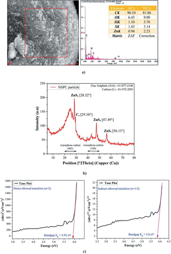
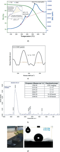
The XRD pattern of NSPC particle was determined and its phases were matched, as shown in with the JCPDS cards (01-077-2100 & 01-072-2091) for the intense diffraction peaks (2θ) (Figure S5). At the same time, the presence of amorphous carbon in the NSPC particles was validated by XRD peaks ascribed to the (002) and (100) planes. Amorphous carbon has the ability to improve the compressive strength of the cement matrix. Furthermore, the crystallite size using Debye-Scherrer equation (Table S2) and crystallinity (Figure S6) of the NSPC particles were found to be ~35 nm and 10.42%, respectively. Noticeably, the quantification results of the phase identification derived from X’Pert-Highscore plus confirmed the presence of 81% pure carbon and 19% ZnS (Figure S7). The UV-Vis absorption spectrum was used to examine the energy gap (electrical conductivity) using Tauc’s method and optical conductivity (electronic state) from Beer-Lambert law. The direct allowed transition of electrons determined the nature of electrical conductivity present in NSPC particles. The wide bandgap energies predicted by Tauc’s plot for direct allowed transition (5.93 eV) and indirect allowed transition (5.8 eV), as depicted in , indicate that sufficient external energy is required for the electrons of the NSPC particle to be transferred from the valence band to the conduction band. On the other hand, the optical conductivity values demonstrated the occupied electronic state in the NSPC particle at 202 nm, 340 nm, and 786 nm (Figure S8). The TGA recorded a total of three mass loss interval regions, ascribed to moisture content evaporation at 35°−300°C, devolatilization process at 300°C−750°C, and the slow combustion at 750°C−800°C. Additionally, the maximum rate of weight loss measured using DTG was observed at 556.1º (−810ug/min) (Figure S9).
The two exothermic phase transformations identified using DSC curves at 367.1°C (64.5 mW) and 552.3°C (126.5 mW) is depicted in , which shows the dominant combustion process resulting in high carbon content with lower ash residue of 22%. From the FT Raman spectrum, it is observed that the defect band is higher than the graphitization band as shown in , indicating the presence of competent graphitic carbon structure with minor defects [Citation38]. Therefore, the ratio of the intensities of the defect band to the graphitization band (ID/IG = 1304/1580) is 0.83 which indicates the obvious quality of NSPC particles. Moreover, shows the Raman spectra which provide evidence for the existence of carboxyl functional groups such as C ≡ C, N‒H Stretch, O‒H Stretch, and CH2 wagging that establishes a strong bonding structure with the adjacent matrix. Dispersing the NSPC particles in water is unfeasible because of their high hydrophobicity, as evidenced by a contact angle of about 141.6º on the pellet surface, as shown in . This indicates that the NSPC particle possesses a hierarchical structure of nanopatterns with a high hydrophobic surface. Simultaneously, the material has a low surface energy of 8.95mJ/m2 which was determined using Young-Dupree equation and the OWRK model. The various characterization results highlight the potential of the NSPC particles to induce its multifunctional properties in CMC owing to their nano-structure and high carbon content. Therefore, influencing NSPC particle as carbon nanomaterial will be an ideal choice for developing electrically conductive composites.
Figure 8. d) TG and DSC curve for NSPC particle, e) ID/IG ratio of NSPC particle, f) FT Raman spectra showing different functional groups present in NSPC particle, g) Water contact angle test on NSPC particle using tangent measuring method.
5.2. Dispersion techniques
represents the sedimentation test results of NSPC particle in different physicomechanical methods. The sedimentation tests for Method 1 and Method 2 were visualized and pictured directly after 20 shakes by hand. Likewise, Method 3 and Method 4 were subjected to mechanical methods such as magnetic stirring and ultrasonication, respectively. In method 1, the NSPC particle dispersed solely with water was almost separated within 15 min and floated at the top due to immediate agglomeration [See a), Method -1]. This indicates the hydrophobic nature of NSPC particle, as their dispersion in water is inadequate without a mechanical or chemical treatment. In method 2, NSPC particle dispersed in the water with polycarboxylate super plasticizer contributed to the homogeneous dispersion and prolonged the separation of particles from water compared to method 1. This indicates that the surface of NSPC particle has been wrapped by polycarboxylate, which may have limited the van der Waals forces between NSPC particle through the steric hindrance, considering the polycarboxylate’s adsorption layer thickness is about 100 Å [Citation79]. Accordingly, the NSPC particle was dispersed at the first instance and did not separate from the solution for up to 8 h [see (a), Method – 2]. However, from (b), it is observed that the NSPC particle separated from the solution after 24 h in relative to Method 1 due to the low surface tension and unmodified hydrophobic surface of NSPC particle with superplasticizer.
Figure 9. a)Sedimentation test for the dispersion state of NSPC particle in four different solutions, b) Comparison of sedimentation test results after 24 hours.
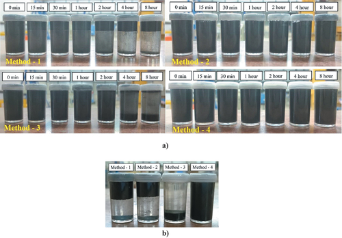
In Method 3, the ethanol + NSPC particle was pre-mixed to modify the surface of the particle and added to the water in the absence of superplasticizer followed by continuous magnetic stirring. As a result, NSPC particle nearly settled after 4 h was clearly different from Method 1 and Method 2. After 24 h, the NSPC particles in the solution were completely settled at the bottom with a height of 10 mm, leaving a clear supernatant (Figure S10), which is minimal compared to the results investigated with xylene for CNT (30 mm) [Citation80]. Although the results from this method exhibit the advantage of surface modification and elimination of large pores in the agglomerates, it is inadequate for homogeneous dispersion of NSPC particle in water. In Method 4, the surface of NSPC particle modified by ethanol is mixed with a superplasticizer-based water solution. The aqueous solution is subjected to magnetic stirring and ultrasonication for 4 h and 1 h, respectively. The beneficial effect of superplasticizer and ultrasonication is confirmed by visual observation [see ), Method − 4], where the NSPC particle showed more uniform and progressive dispersion. Moreover, it also ensured that the NSPC particle remained unchanged in the suspension for 24 h compared to other physicomechanical methods, as depicted in ). The outcome of this result is possibly due to the effect of shear force during the ultrasonication process synergistically stimulating the dispersion of NSPC particle with superplasticizer.
Meanwhile, the zeta potential test was carried out to validate the hypothesis stated from the sedimentation test results. shows the zeta potential values for different dispersion methods. The zeta potential value of NSPC particle in water (Method − 1) was found to be −0.122 mV, thereby indicating the high instability and strong tendency of the nanoparticles to agglomerate in the sole water. Besides, the zeta potential value much closer to zero corroborated the hypothesis that the dispersion of NSPC particle in water is adverse without chemical admixture [Citation81]. In time, the addition of polycarboxylate superplasticizer in water to disperse NSPC particle (Method − 2) increased the zeta potential value to −4.73 mV, which is coherent with sedimentation results. Since polycarboxylate induces a steric hindrance mechanism, it stabilizes the solution and does not expect to obtain a high zeta potential value [Citation81]. Therefore, the value around 5 mV indicates the effective dispersion of nanoparticles compared to Method 1. However, these values are not substantial enough to confirm that the NSPC particles are well dispersed using a superplasticizer in water. The zeta potential value of NSPC particle with ethanol in water is +16.1 mV, which shows that the surface of NSPC particle is positively charged due to the surface modification by ethanol. Furthermore, a value less than +30 mV confirms the hypothesis of the unstable condition of nanoparticles in the solution resulting in agglomerates [Citation82]. While higher zeta potential values of −19 mV are achieved for NSPC suspension with ultrasonication process (Method − 4), as shown in , exhibiting the indication of high dispersion capacity and stability of nanoparticle is protected sterically in the suspension.
Figure 10. Zeta potential value of NSPC particle suspension under ultrasonication process.
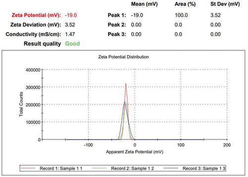
Table 8. Zeta potential values of NSPC particle in different solutions.
The visual observation of sedimentation tests showed explicit differences in the dispersion of NSPC particles in water. The same was validated through significant zeta potential values to select the feasible physicomechanical method. Based on the results, Method − 4 was chosen as an efficient dispersing technique for NSPC particle for subsequent cement mortar mixture preparations, as shown in .
Figure 11. Preparation of NSPC composite using physicomechanical process (method − 4).
5.3. Fresh properties
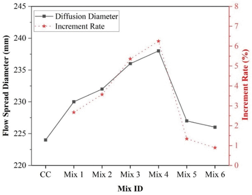
The flowability test results of freshly prepared CMC with different NSPC content are illustrated in in terms of diffusion diameter and increment rate. The higher flowability of mortar mixture depends on the higher diffusion diameter. It was found that increasing the addition of NSPC particle increased the flowability of mortar. The increment rate of 2.14%, 3.24%, 3.86%, and 4.12% is observed for the mixes with the addition of 0.5%, 1.0%, 1.5%, and 2% of NSPC particle, respectively. These results exhibit better rheology properties than previous studies on the flowability of mortar with the addition of carbon black [Citation63,Citation83]. Comparatively, the rate of increment in flowability for the addition of 2.5% and 3% of NSPC was minimal. This is because of the same superplasticizer content and w/b ratio for all mixes. Subsequently, it is deduced that the SF content as a binder can also impact the flowability [Citation63] with more addition of NSPC particle.
Figure 12. Diffusion diameter of CMC with different concentrations of NSPC particle.
5.4. Mechanical properties
5.4.1. Compressive strength
The compressive strength of CMC dispersed with various concentrations of NSPC particle after different curing ages is shown in . Initially, the compressive strength of plain CMC (CC, with 10% SF) are 14.2 MPa, 15.53 MPa, 25.59 MPa, 28.39 MPa, 36.42 MPa, 37.63 MPa, and 39.64 MPa, respectively, on 1, 3, 7, 14, 28, 56, and 90 days. According to the illustrated results, the compressive strength of 1 day and 3-day-old mixtures [See ] were nearly the same to each other, and no considerable shift can be observed between mixtures. The abide time taken to reduce the concentration of calcium ions around the NSPC particle is the reason for the slow hydration process at an early age of compressive strength. However, the composites incorporated with 2 wt.% of NSPC particle (Mix 4) were found to be relatively higher than the CC mix while comparing other mixtures. It is perceived that the addition of NSPC particle had no discernible effect on the early-age compressive strength. In spite of that, the function of NSPC particle in CMC at 7, 14, 28, 56, and 90 days was more specific compared to early-age specimens.
Figure 13. Compressive strength test results of cubic specimens without and with electrodes at different curing ages a) 1 day b) 3 days c) 7 days d) 14 day e) 28 day f) 56 day g) 90 day.
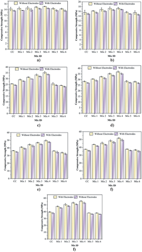
From , it is noticeable that with the increase of NSPC particle dosage from 0–3 wt.%, the compressive strength of CMC differs significantly but demonstrates a similar trend at all curing days. The apparent change in colour of the specimens was observed with the addition of NSPC particle. The compressive strength consistently increased with curing time from CC to mix 4, confirming the reinforcement effect of NSPC particle. It is also noted that the compressive strength of the specimens kept increasing up to 90 days, exhibiting the continued interaction of nanoparticles with the matrix. The maximum strength is achieved for the CMC with 2wt.% NSPC particle, which is 40.37% higher than that of CC mix. At the same time, the CMC with 0.5wt.%, 1wt.%, and 1.5wt.% of NSPC particle enhanced the strength of the specimen to 20.8%, 27.7%, and 34%, respectively. This implies that the addition of NSPC particle can achieve optimal packing, as shown in .
Figure 14. Representation of NSPC composite achieving optimal packing of particles at 90 days.
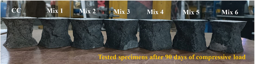
Further, it is visualized from that NSPC particle have reduced the pores in the CMC owing to the filling effect of nano particles. In this regard, SF plays a vital role by not only assisting the hydration but also mechanically separating the NSPC particle from aggregation. At later curing stages, the adhesion property of SF fixes the layer of carbon nanoparticle to hydration products and increases the interfacial strength between NSPC particle and cement matrix, as seen in the SEM image of . Consequently, the compressive strength of the NSPC composites improved with the curing ages. Despite this, the compressive strength begins to decrease when the addition of NSPC particle exceeds 2 wt.% by binder mass. The strength of CMC with 2.5 wt.% (Mix 5) and 3 wt.% NSPC (Mix 6) slightly reduced with respect to the CC mix [See ] but still attained 36.6 MPa and 36.42 MPa, respectively. The wane in compressive strength as the nanoparticle increases is likely due to an overload of filler particles in the matrix. Moreover, there are two primary mechanisms that attribute to the attenuation of compressive strength. First, since the w/b ratio is similar for all the mixes, the high dosage of NSPC particle can considerably absorb water and hinder the hydration process. Secondly, at higher concentrations, the hydrophobic nature of NSPC particle possessess a relatively weak interface between NSPC particle and the cement matrix. Interestingly, an increase in NSPC content to 2.5 wt.% and 3 wt.% has no negative influence which is plausible that NSPC particles aggregate only up to a certain limit. The obtained result exhibits that Mix 4 has the highest compressive strength, showing a similar trend with flowability (See ) and the dispersion of NSPC particle is achieved without compromising the strength properties.
Figure 15. Core samples showing the filling effect of NSPC particle in CMC.
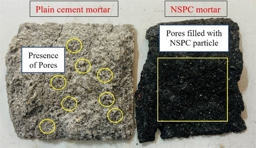
Figure 16. Interfacial transition zone between the NSPC particle and cement hydration products.
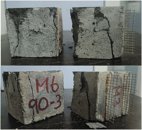
Besides the investigation of the compressive strength of various mixtures, the effect of electrodes on the compressive strength of CMC was also examined. also exhibits the comparison of compressive strength on cubic specimens with and without electrodes. The specimens with two steel mesh electrodes were tested for compressive loading along with preliminary specimens at all curing ages. The maximum compressive strength was 52.88 MPa for Mix 4 specimens embedded with electrodes. The difference in the failure pattern for the cubic specimens with and without electrodes is shown in . From the results of the preliminary investigation (specimens without electrodes), it is observed that using two steel mesh electrodes led to a 4–5% reduction in the compressive strength. However, it can be determined that the compatibility of the two probe method is considerable in terms of compressive strength with negligible loss percentage.
Figure 17. Failure pattern of cubic specimens with and without electrodes after compressive strength.
5.4.2. Flexural strength
depicts the average flexural strength results of different mortar mixtures with the addition of NSPC particle. The trend for flexural strength is first decreased substantially with 0.5 wt.% of NSPC particle and then a sudden increase is observed with the addition of NSPC content between 1 wt.% and 1.5 wt.%, which is against the trend of compressive strength. demonstrates the increment and decrement rate variations of flexural and compressive strength with filler content. Noticeably, the significant decrement rate observed for flexural strength at Mix 1 and Mix 2 is unlike the compressive strength, where the adsorption of NSPC on the surface of cement has affected the hydration. Further, the reduction in flexural strength is caused by the growth of cracks in the bulk of materials during the flexural test [Citation71]. Moreover, the gradual decrement rate in flexural strength is observed past the addition of 1.5 wt.% NSPC particle. However, the CMC with 2 wt.% of NSPC and above attained higher flexural strength than the CC mix.
Figure 18. Flexural strength of NSPC composites.
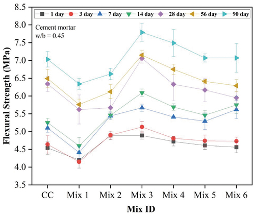
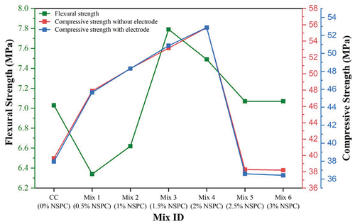
Figure 19. Comparison between the flexural and compressive strength of NSPC composites.
The 90 days flexural strength of CMC with the addition of 1.5 wt.% and 2 wt.% NSPC particle yielded 7.79 MPa and 7.49 MPa, which is 10.76% and 6.5% higher than the CC mix. A considerable enhancement in flexural strength is observed from 1 to 90 days of curing without regard to the type of mixtures. However, the relationship between CC and NSPC composites at an early age was similar to compressive test results where no explicit trends were observed at 1 day and 3 days. The CMC having 1.5 wt.% of NSPC particle achieved high flexural strength at all curing ages. Therefore, curing enhancement has reduced the pore size and increased the bonding between NSPC particle and cement matrix resulting in high flexural strength. At the same time, the lowest flexural strength (5.62MPa/28 days curing) recorded in this study for the CMC with 0.5 wt.% of NSPC particle is slightly greater than the study achieved with commercial carbon black [Citation84]. The mechanical performance of NSPC composite compared among different cement composites is shown in .
Table 9. Mechanical property performance comparison of NSPC composite with existing literatures.
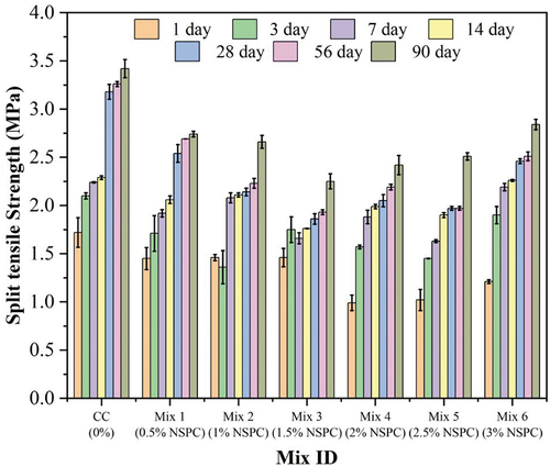
5.4.3. Split tensile strength
There is no extensive study between the carbon nanoparticle and split-tensile strength. In this study, the split-tensile strength was obtained over cumbersome direct tensile strength, which is difficult to perform and data scatters. The split-tensile strength of CMC incorporated with different percentages of NSPC particle, as obtained from the experimental results is shown in . From the figure, it is observed that all the NSPC composites (Mix 1 to Mix 6) provided less split-tensile strength compared to the CC mix. This is because NSPC particle acted only as fillers under tension which is unproductive in bridging the cracks at nanoscale. It is also observed that the NSPC composite cured for 90 days has enhanced 15–25% higher tensile strength compared to 28 days cured composites. Conversely, poor split-tensile strength was recorded for all the mixes at 1 day of curing similar to compression and flexural results. Therefore, curing age plays a vital role in altering the strength of the NSPC composites. Further, enhancement in the curing age provided linear improvement in the split-tensile strength. The CMC with 3 wt.% of NSPC particle attained a high split-tensile strength of 2.84 MPa at 90 days, which is 80% of the strength of the composites without NSPC particle (CC mix). Interestingly, the strength of this composite (Mix 6) at 7 and 14 days of curing age achieved higher strength than the CC mix. From this, it is inferred that the dosage of NSPC particle affected the split-tensile strength of CMC by modifying the compressive and flexural strength.
Figure 20. Split-tensile strength results of NSPC composites using cylinder specimens.
5.5. Water absorption, permeable voids, and dry density
The water absorption, dry bulk density, and volume of permeable pore space of the NSPC composites at 90 days are summarized in respectively. The filling effect of NSPC particle was efficient in reducing the water absorption of CMC. The pattern of deterioration in the rate of water absorption was similar to the trend of compressive strength. In addition, the effect of 10% SF in cement mortar can decrease the rate of water absorption [Citation63] by reducing the nanomaterial agglomeration exhibiting better dispersion of NSPC particle. Concurrently, the influence of NSPC particle slightly improved the dry bulk density of the CMC as it is closely related to the packing of fine particles. The dry bulk density of NSPC composites was increased by 2.21% (Mix 1), 3.04% (Mix 2), 5.52% (Mix 3), 8.84% (Mix 4), 7.18% (Mix 5), and 4.14% (Mix 6) compared plain CMC. The highest dry bulk density of 3.94 Mg/m3 in the group of all mixes was observed in Mix 4, which is largely relevant to the concentration of NSPC particle. The water absorption and bulk density measured at different testing stages are shown in Table S4.
Figure 21. a) water absorption b) dry bulk density and c) volume of permeable pore space at 90 days of hydration of NSPC composites.
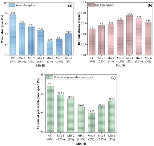
Furthermore, the addition of NSPC particle stimulated a reduction in the volume of permeable pore space by 7.32% (Mix 1), 10.44% (Mix 2), 16.98% (Mix 3), 21.9% (Mix 4), 16.7% (Mix 5), and 12.12% (Mix 6) compared to plain CMC. These results showed that the NSPC particle further decreased the porosity of CMC, showing that the connections at intervals of void space in the matrix are decreased [Citation90]. The synergistic contribution of SF and NSPC particle reduces the interconnectivity of permeable voids promoting the bonding of binder and solid bulk density resulting in increased mechanical properties of NSPC composites. The maximum reduction in permeable voids was achieved for 2 wt.% and 1.5 wt.% of NSPC particle, corroborating the compressive and flexural strength results, respectively, as discussed in the previous sections. The reduction in the volume of permeable pore space indicates that the voids in the CMC were packed by the addition of NSPC particle, which enhanced the microstructure and, consequently, improving the electrical conductivity.
5.6. Electrical properties
5.6.1. Electrical resistivity of NSPC composites under AC method
The measurements of DC electrical resistivity conducted on the plain CMC and NSPC composites at different curing days are illustrated in . From the figure, it is well spotted that the DC electrical resistivity is reduced distinctly when NSPC particle is added in various concentrations into CMC. The reduction of resistivity is mainly due to the increase in carbon content within the matrix which provides conductive paths and enables conductive compounds [Citation91]. There are no previous studies that have been performed on the electrical properties of CMC with NSPC particle. Nevertheless, the observed results in this study are related to the investigations conducted with other types of nano functional fillers. In this study, the DC electrical resistivity decreased gradually with increasing content of NSPC particle from 0.5 wt.% to 1 wt.%. This range is called the insulation zone (i.e. zone I), as shown in the figure, where the ionic conduction will be the main path instead of a conductive path with less amount of NSPC particle to contact each other. When the content of NSPC particle in the CMC is increased beyond 1 wt.% (i.e. 1.5 wt.% to 2 wt.%), the DC electrical resistivity decreases promptly. This rapid decrease in resistivity implies a significant amount of NSPC particle from a percolation phenomenon (beginning of conductive paths), which is called a percolation zone (zone II) [Citation32,Citation92], as seen in the figure. In this zone, the resistivity is reduced by the combined mechanism of contact conduction and tunneling current. With the addition of 2.5 wt.% and 3 wt.% of NSPC particle in CMC, the DC electrical resistivity decreases slightly exhibiting that the NSPC particle has attained saturation. This is called conduction zone (zone III), where the domination of contact conduction occurs [Citation20]. Noticeably, the DC electrical resistivity of CMC with 2–3 wt.% of NSPC particle is two orders of magnitude lesser than that of other mixes at all curing ages. Therefore, the percolation threshold is assumed to be 2 wt.% of NSPC particle.
Figure 22. DC electrical resistivity of CMC with NSPC particle.
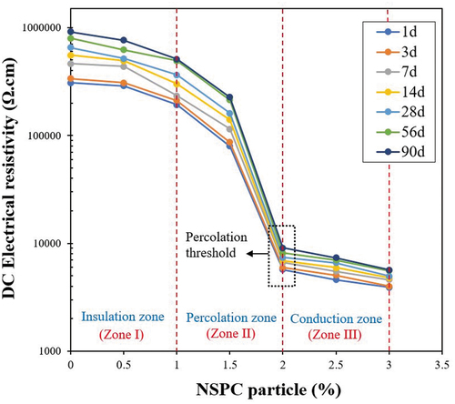
Moreover, it is observed that the DC electrical resistivity increased in all mixes as the curing age increases. The rationale behind this change is that the adsorbed water limits the conductive paths in the cement matrix owing to the recurrent hydration of cement [Citation93]. In addition, the DC electrical resistivity of the composites is governed by ionic conduction. When the specimens are tested from 1 day to 90 days, the DC electrical resistivity of NSPC composites with 0 wt.%, 0.5 wt.%, 1 wt.%, 1.5 wt.%, 2 wt.%, 2.5 wt.%, and 3 wt.% increases about 195.7%, 166.1%, 164.5.1%, 185.97%, 59.85%, 58.93%, and 45.5%, respectively. Accordingly, it is also observed that the increase in DC resistivity of NSPC composites (M1-M6) is comparatively less than that of the corresponding value of plain CMC under different curing ages. The DC electrical resistivity of CMC with NSPC particle of 0.5 wt.%, 1 wt.%, & 1.5 wt.% are greatly affected by the degree of cement hydration due to ionic conduction and several polarization states at different curing ages. Meanwhile, the DC electrical resistivity with NSPC particle of more than 2 wt.% gradually increases the conductive network which has little effect on cement hydration. Consequently, the observed trend of constant variation becomes relatively stable with curing age.
5.6.2. Electrical resistivity of NSPC composites under DC method
The electrical resistivity of CMC as a function of NSPC particle content measured by using AC method is depicted in . This figure shows the variations in AC electrical resistivity with respect to both curing age and frequency of 100 Hz, 1 kHz, 10 kHz, & 100 kHz, as shown in . On the one hand, the AC electrical resistivity decreases in all the composites under the same curing age when the frequency is increased from 100 Hz to 100 kHz. This feature shows the weakened polarization effect in the composites under high frequency. On the other hand, AC electrical resistivity increases in all composites with curing age from 1 to 90 days because of the alteration in the microstructure due to hydration which leads to isolated pores. A similar trend in AC electrical resistivity was observed in the previous investigation with GNP/CNT and NCB/CNT composites [Citation64,Citation74]. At the same time, it is apparent that the increased AC electrical resistivity with curing time decreased with higher NSPC content (2–3 wt.%). From the results of AC method, the electrical resistivity decreased with increasing content of NSPC particle. The percolation zone in the AC electrical resistivity ranges from 1 wt.% to 2 wt.% and the established percolation threshold is at 2 wt.%, which is similar to the results of DC electrical resistivity. However, the resistivity values of DC to AC method decreased from 9078 Ω.cm to 5656 Ω.cm (100 kHz) for 2 wt.% of NSPC particle at 90 days. This indicates that the AC electrical resistivity will not produce polarization voltage owing to sinusoidal variations at high AC frequencies [Citation94]. In addition, the pi electrons distributed over a larger region of space in NSPC particle are responsible for the formation of pi bonds that contribute to good electrical conductivity characteristics [Citation95].
Figure 23. AC electrical resistivity of CMC with NSPC particle for different frequency a) 1day b) 3 days c) 7 days d) 14 days e) 28 days f) 56 days g) 90 days.
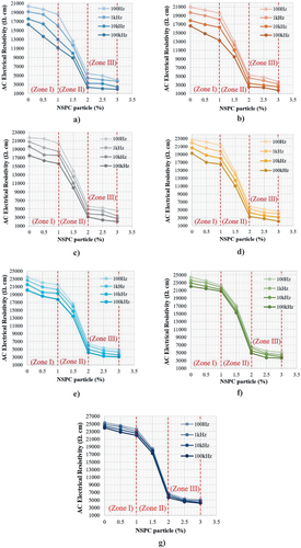
Therefore, it is ascertained that the addition of NSPC particle in CMC has the ability to reduce the electrical resistivity. However, while comparing these results with previous research, the electrical resistivity of NSPC composites is paltry higher than the other nanocomposites [Citation32,Citation74,Citation80]. shows the performance comparison of NSPC composites with different researches. This indicates that the particle type functional fillers are inconsistent in decreasing the electrical resistivity of the composites compared to fibrous fillers [Citation79]. It is anticipated that NSPC particle with fibrous functional fillers has the possibility to achieve the best reduction ability on electrical resistivity. Nevertheless, NSPC particle was effective in improving the conductive network in the cement matrix. The electrical resistivity for Mix 6 (3 wt.% of NSPC) with a curing age of 90 days is 5665 Ω.cm and 4197 Ω.cm for DC and AC method, respectively. Eventually, the attained electrical resistivity by incorporating NSPC particle into cement matrix assisted in developing electrically conductive composites.
Table 10. Electrical resistivity performance comparison of NSPC composite with existing research.
5.7. Microstructure properties
5.7.1. XRD – hydration phases
XRD test was performed after different curing ages to examine further the impact of NSPC particle on the phase formation of the hydration products. illustrates the XRD patterns of 1 day, 7 days, 28 days, and 90 days, respectively. The results were qualitatively analyzed with an open crystallographic database to determine the phase arrangement. In this study, the main hydration products including Calcium Hydroxide (CH), Calcium-Silicate-Hydrate (C-S-H), and Ettringite (Aft) are observed in the CMC. On the other hand, the anhydrous clinker including Calcium Silicate phases (CS) (i.e. di-calcium silicate/tri-calcium silicate) and Silica Oxide (SiO2) are also measured. From the figure, it is observed that the plain CMC and NSPC composite exhibited similar peaks with different intensities irrespective of curing age. The formation of ettringite is very less which attributes to the 10% of SF filled in all composites. The main reasons stated are the more calcium ions are converted into C-S-H and the addition of nanoparticles which can absorb water content resulting in an attenuated hydration rate [Citation63]. In the CC mix, a significant reduction in the CH peaks is observed with the increasing hydration age. This is because of the pozzolanic interaction between SF and calcium hydroxide (induced from cement hydration), where the CH is consumed when the curing age is increased from 1 to 90 days. In NSPC composites, the intensity of CH peaks increased up to 7 days of hydration and then decreases from 28 to 90 days of hydration. This indicates that the addition of NSPC particle inhibits the hydration process at an early age by delaying the pozzolanic interaction between SF and CH. These findings agree with the results of mechanical strength.
Figure 24. XRD pattern of CMC containing NSPC particle a) 1 day b) 7 days c) 28 days d) 90 days.
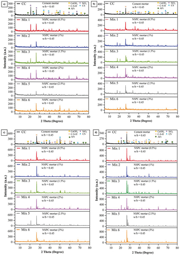
Similarly, as the curing age increases, the peak intensities of CS phases (unhydrated phases) decrease. However, the CS phase still exists until 90 days of hydration. At the same time, the formation of CS phases due to unstable calcium carbonate in NSPC composite increased with the addition of NSPC particle and again decreased with increased NSPC content as evidenced at 2θ of 50.4°. At the age of 1 day, it is evident that the presence of NSPC particle delayed the hydration of clinker exhibiting high intensities of SiO2. Furthermore, the clinker grains are converted into C-S-H with increased hydration time and the continuous hydration attributes to augment the intensity of C-S-H. In addition, a significant increase in C-S-H is seen in the vicinity of 26.5° at 7, 28, & 90 days of hydration, respectively. From , the diffraction peaks at 60.5° representing the C-S-H content show that the intensity of C-S-H increased with the addition of NPSC particle and reduced beyond the percolation threshold (2 wt.%), which agrees with the trend observed in the compressive strength of the NSPC composites. Furthermore, XRD analysis revealed no new diffraction peaks in the NSPC composites. Therefore, it can be concluded that NSPC particle did not alter the hydration pathway and the high amorphous carbon reduced the crystallinity degree of further formed hydration products, forming optimal packing structure in NSPC composites.
5.7.2. Micromorphology of NSPC composites
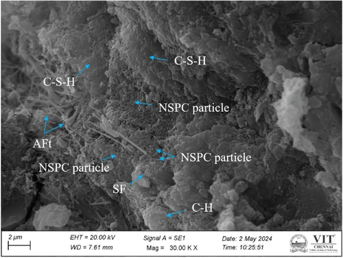
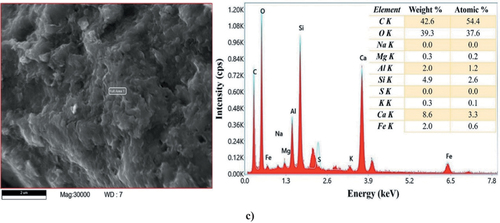
The electrical conductivity behavior of NSPC composites greatly depends on the effective dispersion of NSPC particle. shows the morphology of CMC with NSPC particle and SF, where the NSPC particles are well dispersed/distributed all over the matrix which confirms the efficiency of the proposed dispersion method. The typical morphology at nanoscale shows that the NSPC particle are well embedded on the surface of CH and entangled in SF. It is also seen that the NSPC particles are distributed as aggregate like structures instead of lone particles, where the interconnected network establishes continuous conductive channels [Citation97]. shows the HR-SEM images of 28 days of CMC with different concentrations of NSPC particle. The HR-SEM results clearly exhibit the presence of C-S-H, Aft, and CH, similar to the carbon black composites which are previously reported in the literature [Citation63,Citation83,Citation87,Citation98]. These hydration products contributed to the strength of the CMC forming a dense matrix. While comparing the CC mix with other mixes, it is clear that the addition of NSPC particle significantly improved the density of matrix by filling the voids. This indicates that the NSPC mainly plays a filling and reinforcing effect to obtain a denser microstructure, and consequently enhanced the mechanical properties. Moreover, it can be seen that Mix 3 (1.5 wt.%) and Mix 4 (2 wt.%) have denser microstructure compared to other mixes, where several hydration products are appeared surrounding NSPC particle. This indicates the strong interference between the particles of hydration product resulting in high flexural and compressive strength for Mix 3 and Mix 4, respectively. However, it is noticed that Mix 5 (2.5 wt.%) and Mix 6 (3 wt.%) contain more AFt and agglomerates of NSPC leading to a weak interface with cement matrix results in lower mechanical properties as discussed in the previous sections. It is also proved by XRD analysis [see ] that the high intensity of CS indicates insufficient water content to complete the hydration reaction by increasing the amount of NSPC particle. Successively, the synergistic effect of SF and highly filled with NSPC particle in the cement mortar have higher conductivity and warrant effective electrical resistivity in CMC. The EDAX results of NSPC composite are represented in the , where the composite contains C, Si, O, & Ca as main elements. The results of EDAX analysis conducted on each NSPC composite sample (i.e. M1 to M6) are listed in Table S3 and Figure S11 (a)-(g). It is observed that the amount of elemental composition C is high compared to Si, O, & Ca. Subsequently, the elemental composition exhibiting high intensity of Si, O, & Ca indicates the presence of cement hydration products which have wrapped and covered the NSPC particle. This shows the improved bonding performance between the NSPC particles and hydration products. It is ascertained that the uniform distribution of NSPC particle enhances the continuity of the CMC microstructure and contributes to decreased electrical resistivity.
Figure 25. a) morphology of NSPC composites at micro and nano scale, b) HR-SEM images showing microstructure of different NSPC composites.
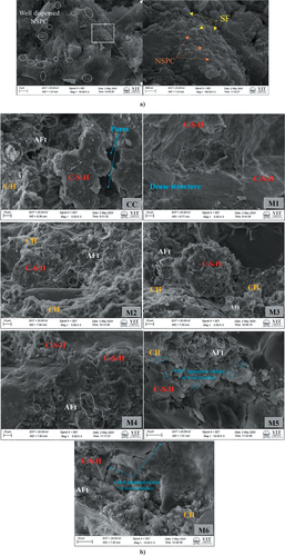
Figure 25. c)HR-SEM images showing microstructure of different NSPC composites.
6. Cost analysis
The preparation cost of the NSPC composite is analyzed and compared with nanocomposites reinforced with commercial nanomaterials (CNT, GO, and GNP). The specimen preparation cost for all the mixes was computed for one mortar cube (50 × 50 × 50 mm) by determining the cost of nanomaterial and raw materials. The cost of the materials was estimated according to the Chennai, India, market price and the obtained results of cost analysis is represented in . Further, the evaluation was performed based on the total cost and the compressive strength of NSPC composite using EI value.
Table 11. Cost analysis of different NSPC composite mixes.
From the calculated results of cost analysis, it is noticed that NSPC-0.5 wt.% mortar mix had the highest EI value when compared with the other mixes. However, NSPC-2 wt.% mortar mix was the optimum of all mixes according to the strength parameter. In previous investigations, it is observed that the cement composites incorporated with commercial nanomaterials such as CNT, GNP, & GO were expensive indicating very low EI value [Citation99], when comparing with this study. Meanwhile, the highest EI value was recorded as 2.98, 0.44, and 3.49 for CNT-0.04, GO-0.04, and GNP-0.04, respectively [Citation99], which is 46%, 92%, and 37% lower compared to NSPC-2 wt.% mix. Consequently, the cost analysis shows that the NSPC particle as SCN will be economically feasible with improved strength characteristics to develop electrically conductive composites.
7. Conclusions
In this study, NSPC particle was introduced as SCN to fabricate electrically conductive cement mortar composites. This research established all the feasible characterization techniques to understand the physicochemical interaction of NSPC particle discovered from pyrolyzed waste tyre. A physicomechanical method was proposed to dispersion of NSPC particle in water, and its dispersion state was analyzed by the sedimentation and zeta potential tests. A series of experimental programs such as flowability, mechanical properties, water absorption, DC & AC resistivity, and microstructure analysis was conducted to evaluate the effect of NSPC particle on CMC. The research findings from this study are recapitulated as follows.
The characterization results exhibit the potential perception of NSPC particle as SCN, which has the ability to influence the electrical property in cementitious composites owing to their nanostructure (2D/55 nm) with crystallite size of ~35 nm, bandgap of 5.8 eV, and high carbon content (>90%). However, the water contact angle measurement of about 141.6° and low surface tension of 8.95mJ/m2 hinders the dispersion of NSPC particle in water.
The results of sedimentation and zeta potential measurement showed that using the combination of polycarboxylate superplasticizer, ethanol, magnetic stirring (4 h), and ultrasonication (1 h) resulted in a highly homogeneous NSPC particle dispersion in aqueous solution.
The rheology properties of NSPC composites showed a better increment rate (4.12%) in flowability results with addition of NSPC particle up to 2 wt.% and a significant decrease in flowability is observed with further increase of NSPC particle.
The compressive strength of NSPC composite is increased with curing age by addition of NSPC particle but no significant increment is observed at early ages. Moreover, the adhesion property of SF assists in distributing the nanoparticles to increase the interfacial transition zone in the CMC. On the other hand, flexural strength decreased and increased with addition of NSPC particle. However, both compressive and flexural strength started to reduce with more addition of NSPC particle (>2 wt.%) owing to water adsorption. The highest compressive and flexural strength was observed for the NSPC composites containing 2 wt.% and 1.5 wt%, with a value of 55.65 MPa and 7.79 MPa, respectively. The rate of decrement in split-tensile strength with addition of NSPC particle is higher than compressive and flexural strength. However, the tensile strength of NSPC composites with 3 wt.% (Mix 6) maintained about 80% of 90-day strength of CC mix.
Addition of NSPC particle reduced the volume of permeable pore space and rate of water absorption, reinforcing the microstructure and contributes to electrical conductivity.
Electrical conductivity of CMC can be enhanced by the addition of NSPC particle. Both DC and AC electrical resistivity of NSPC composites decreased while increasing the dosage of NSPC particle but marginally increased with hydration time. The DC and AC electrical resistivity of NSPC composite is reduced by two orders and one order of magnitude, respectively. While the percolation threshold is demonstrated at 2 wt.% of NSPC content for both the DC and AC method.
XRD analysis indicated that the incorporation of NSPC particle can inhibit the hydration process at an early age. Nevertheless, the hydration pathway is unaltered and continuous hydration attributes augment in C-S-H forming optical packing structure. Microstructural morphologies showed reduced agglomeration and well-distributed NSPC particle on the surface of hydration products with SF.
The cost analysis calculated in terms of EI for the best NSPC composite (2 wt.%) is 5.54, which shows NSPC particle as SCN is economically sustainable in developing electrically conductive composites.
In summary, the results of this study highlight the potential of the dispersing NSPC particles to induce mechanical, electrical, microstructural, and durability enhancement in CMC due to their nanostructure and high carbon content. Eventually, the present investigation set down the methodology for the transformation of tyre-char into an SCN to assist in the development of smart NSPC-based electrically conductive composites.
Abbreviations
| AC | = | alternating current |
| AFt | = | ettringite |
| Al2O3 | = | aluminum oxide |
| BJH | = | Barrett Joyner Halenda |
| BET | = | Brunauer-Emmett-Teller |
| CaO | = | calcium oxide |
| CH | = | calcium hydroxide |
| CHNSO | = | carbon hydrogen nitrogen sulfur oxygen |
| CS | = | calcium silicate |
| CMC | = | cement mortar composite |
| CNT | = | carbon nanotube |
| C | = | carbon |
| C-S-H | = | calcium silicate hydrate |
| DBP | = | Dibutyl Phthalate |
| DC | = | direct current |
| CHNSO | = | carbon hydrogen nitrogen sulfur oxygen |
| DTG | = | derivative thermogravimetric |
| DSC | = | differential scanning calorimetry |
| ECC | = | engineering cementitious composites |
| EDAX | = | energy dispersive x-ray analysis |
| EI | = | economy index |
| Fe2O3 | = | iron oxide |
| FTR | = | fourier transform raman |
| GNP | = | graphene nanoplates |
| GO | = | graphene oxide |
| H | = | hydrogen |
| HPCC | = | high performance cement composite |
| HR-SEM | = | high resolution scanning electron microscope |
| HSCC | = | high strength cement composite |
| K2O | = | potassium oxide |
| MgO | = | magnesium oxide |
| MRAI | = | Material Recycling Association of India |
| MnO | = | manganese oxide |
| N | = | nitrogen |
| Na2O | = | sodium oxide |
| NCB | = | nano carbon black |
| NSPC | = | Nano-Structure Pyrolytic Carbon |
| LOI | = | loss on ignition |
| O | = | oxygen |
| OPC | = | ordinary portland cement |
| OWRK | = | owens wendt rabel kaelble |
| P2O5 | = | phosphorus pentoxide |
| PCM | = | phase change material |
| S | = | sulfur |
| SP | = | superplasticizer |
| SCM | = | supplementary cementitious materials |
| SiO2 | = | silicon dioxide |
| SCN | = | sustainable carbon nanomaterial |
| SF | = | silica fume |
| SO3 | = | sulfur trioxide |
| TiO2 | = | titanium dioxide |
| TGA | = | thermal gravimetric analysis |
| UV-Vis | = | ultra violet visible |
| W/B | = | water to binder ratio |
| WCA | = | water contact angle |
| XRF | = | x-ray fluorescence |
| XRD | = | x-ray powder diffraction |
| ZnS | = | zinc sulphide |
Credit author statement
N. K. Karthikeyan: Conceptualization, Methodology, Validation, Investigation, Writing – Original Draft, Writing – Review & Editing, Visualization. S. Elavenil: Writing – Review & Editing, Supervision, Project administration.
Supplementary Data.docx
Download MS Word (14.2 MB)RESPONSE TO REVIEWERS.docx
Download MS Word (121.2 KB)Acknowledgments
The authors would like to thank School of Civil Engineering and School of Advanced Sciences, Vellore Institute of Technology, Chennai, India for providing support and lab facilities to carry out this research. We thank the “DST and SAIF/IIT/M”, “STIC CUSAT”, “National Centre for Earth Science Studies – Thiruvananthapuram”, and “School of Advanced Sciences, VIT-Chennai”, for providing the analytical services. The authors also express their gratitude for permitting to utilize the pyrolysis plant by “GS Pyro Enterprise Pvt. Ltd., India” and for the superplasticizer donated by “Master Builders Solutions, India”.
Disclosure statement
No potential conflict of interest was reported by the author(s).
Supplementary material
Supplemental data for this article can be accessed online at https://doi.org/10.1080/19475411.2024.2386667
Additional information
Funding
References
- Praveenkumar TR, Vijayalakshmi MM, Meddah MS. Strengths and durability performances of blended cement concrete with TiO2 nanoparticles and rice husk ash, constr. Build Mater. 2019;217:343–351. doi: 10.1016/j.conbuildmat.2019.05.045
- Lu Z, Hou D, Meng L, et al. Mechanism of cement paste reinforced by graphene oxide/carbon nanotubes composites with enhanced mechanical properties. RSC Adv. 2015;5(122):100598. doi: 10.1039/c5ra18602a
- Xiao M, Xi J, Qiu P, et al. Evaluation of tensile properties and cracking potential evolution of fly ash-cement mortar at early age based on digital image correlation method. Constr Build Mater. 2024;412:134855. doi: 10.1016/j.conbuildmat.2023.134855
- McCarter WJ, Starrs G, Chrisp TM. Electrical conductivity, diffusion, and permeability of Portland cement-based mortars. Cem Concr Res. 2000;30(9):1395–1400. doi: 10.1016/S0008-8846(00)00281-7
- Rahman I, Singh P, Dev N, et al. Improvements in the engineering properties of cementitious composites using nano-sized cement and nano-sized additives. Materials (Basel). 2022;15(22):8066. doi: 10.3390/ma15228066
- Dehghani A, Aslani F. The effect of shape memory alloy, steel, and carbon fibres on fresh, mechanical, and electrical properties of self-compacting cementitious composites. Cem Concr Compos. 2020;112:103659. doi: 10.1016/j.cemconcomp.2020.103659
- Jin Y, Xia N, Gerhardt RA. Enhanced dielectric properties of polymer matrix composites with BaTiO3 and MWCNT hybrid fillers using simple phase separation. Nano Energy. 2016;30:407–416. doi: 10.1016/j.nanoen.2016.10.033
- Turk K, Cicek N, Katlav M, et al. Electrical conductivity and heating performance of hybrid steel fiber-reinforced SCC: the role of high-volume fiber and micro fiber length. J Build Eng. 2023;76:107392. doi: 10.1016/j.jobe.2023.107392
- Santillán N, Speranza S, Torrents JM, et al. Evaluation of conductive concrete made with steel slag aggregates, constr. Build Mater. 2022;360:129515. doi: 10.1016/j.conbuildmat.2022.129515
- Lim S, Lee W, Choo H, et al. Utilization of high carbon fly ash and copper slag in electrically conductive controlled low strength material, constr. Build Mater. 2017;157:42–50. doi: 10.1016/j.conbuildmat.2017.09.071
- Hambach M, Moller H, Neumann T, et al. Carbon fibre reinforced cement-based composites as smart floor heating materials, compos. Part B. 2016;90:465–470. doi: 10.1016/j.compositesb.2016.01.043
- Gao S, Wang Q, Guo H, et al. High strength and high electrical conductivity Cu composites reinforced by SiO2 aerogel particles. J Mater Res Technol. 2023;24:2346–2356. doi: 10.1016/j.jmrt.2023.03.153
- Li J, Qin Q, Sun J, et al. Mechanical and conductive performance of electrically conductive cementitious composite using graphite, steel slag, and GGBS. Struct Concr. 2022;23:533–547. doi: 10.1002/suco.202000617
- Jo KS, Il Kim N, Seok Kim K, et al. A study on the electrical and physical properties of mortar incorporating carbon black. J Korean Ceram Soc. 2021;58(4):414–421. doi: 10.1007/s43207-021-00111-x
- Han J, Pan J, Cai J, et al. A review on carbon-based self-sensing cementitious composites. Constr Build Mater. 2020;265:120764. doi: 10.1016/j.conbuildmat.2020.120764
- Hemalatha T, Sangoju B, Vasudevan P. Investigation of the influence of unburnt carbon and aggregate type on electrical resistivity of cement mortar. J Inst Eng Ser A. 2022;103(3):797–802. doi: 10.1007/s40030-022-00644-2
- Ding S, Xiang Y, Ni Y-Q, et al. In-situ synthesizing carbon nanotubes on cement to develop self-sensing cementitious composites for smart high-speed rail infrastructures. Nano Today. 2022;42:101438. doi: 10.1016/j.nantod.2022.101438
- Qin H, Ding S, Ashour A, et al. Revolutionizing infrastructure: the evolving landscape of electricity-based multifunctional concrete from concept to practice, Prog. Mater Sci. 2024;145:101310. doi: 10.1016/j.pmatsci.2024.101310
- Ding SQ, Wang XY, Qiu LS, et al. Self-sensing cementitious composites with hierarchical carbon fiber-carbon nanotube composite fillers for crack development monitoring of a maglev girder. Small. 2023;19(9). doi: 10.1002/smll.202206258
- Kanagasundaram K, Solaiyan E. Smart cement-sensor composite: the evolution of nanomaterial in developing sensor for structural integrity. Concr. 2023;24(5):6297–6337. doi: 10.1002/suco.202201145
- Onaizi AM, Huseien GF, Lim NHAS, et al. Effect of nanomaterials inclusion on sustainability of cement-based concretes: a comprehensive review. Constr Build Mater. 2021;306:124850. doi: 10.1016/j.conbuildmat.2021.124850
- Birenboim M, Nadiv R, Alatawna A, et al. Reinforcement and workability aspects of graphene-oxide-reinforced cement nanocomposites, compos. Part B Eng. 2019;161:68–76. doi: 10.1016/j.compositesb.2018.10.030
- Raveendran N, Vasugi K. Synergistic effect of nano silica and metakaolin on mechanical and microstructural properties of concrete: an approach of response surface methodology, case stud. Constr Mater. 2024;20:e03196. doi: 10.1016/j.cscm.2024.e03196
- Mansouri Sarvandani M, Mahdikhani M, Aghabarati H, et al. Effect of functionalized multi-walled carbon nanotubes on mechanical properties and durability of cement mortars. J Build Eng. 2021;41:102407. doi: 10.1016/j.jobe.2021.102407
- Ata S, Hayashi Y, Nguyen Thi TB, et al. Improving thermal durability and mechanical properties of poly(ether ether ketone) with single-walled carbon nanotubes. Polym (Guildf). 2019;176:60–65. doi: 10.1016/j.polymer.2019.05.028
- Ali Z, Yaqoob S, Yu J, et al. Critical review on the characterization, preparation, and enhanced mechanical, thermal, and electrical properties of carbon nanotubes and their hybrid filler polymer composites for various applications. Compos Part C Open Access. 2024;13:100434. doi: 10.1016/j.jcomc.2024.100434
- Ren Z, Sun J, Tang W, et al. Mechanical and electrical properties investigation for electrically conductive cementitious composite containing nano-graphite activated magnetite. J Build Eng. 2022;57:104847. doi: 10.1016/j.jobe.2022.104847
- Kırgız MS. Green cement composite concept reinforced by graphite nano-engineered particle suspension for infrastructure renewal material, compos. Part B Eng. 2018;154:423–429. doi: 10.1016/j.compositesb.2018.09.012
- Zhang P, Wang M, Han X, et al. A review on properties of cement-based composites doped with graphene. J Build Eng. 2023;70:106367. doi: 10.1016/j.jobe.2023.106367
- Dung NT, Su M, Watson M, et al. Effects of using aqueous graphene on behavior and mechanical performance of cement-based composites, constr. Build Mater. 2023;368:130466. doi: 10.1016/j.conbuildmat.2023.130466
- Nalon GH, Ribeiro JCL, de Araújo END, et al. Effects of different kinds of carbon black nanoparticles on the piezoresistive and mechanical properties of cement-based composites. J Build Eng. 2020;32:101724. doi: 10.1016/j.jobe.2020.101724
- Liu L, Xu J, Yin T, et al. Improving electrical and piezoresistive properties of cement-based composites by combined addition of nano carbon black and nickel nanofiber. J Build Eng. 2022;51:104312. doi: 10.1016/j.jobe.2022.104312
- Wang X, Feng D, Meng J, et al. Double percolation phenomenon of carbon nanotube/cement composites as piezoresistivity sensing elements in concrete with exposure to salt environment. Cem Concr Compos. 2024;147:105401. doi: 10.1016/j.cemconcomp.2023.105401
- Mesquita E, Sousa I, Vieira M, et al. Investigation of the electrical sensing properties of cementitious composites produced with multi-wall carbon nanotubes dispersed in NaOH. J Build Eng. 2023;77:107496. doi: 10.1016/j.jobe.2023.107496
- Wang H, Gao X, Wang R. The influence of rheological parameters of cement paste on the dispersion of carbon nanofibers and self-sensing performance, constr. Build Mater. 2017;134:673–683. doi: 10.1016/j.conbuildmat.2016.12.176
- Maga D, Aryan V, Blomer J. A comparative life cycle assessment of tyre recycling using pyrolysis compared to conventional end-of-life pathways. Resour Conserv Recycl. 2023;199:107255. doi: 10.1016/j.resconrec.2023.107255
- Martínez JD, Cardona-Uribe N, Murillo R, et al. Carbon black recovery from waste tire pyrolysis by demineralization: production and application in rubber compounding. Waste Manag. 2019;85:574–584. doi: 10.1016/j.wasman.2019.01.016
- Maroufi S, Mayyas M, Sahajwalla V. Nano-carbons from waste tyre rubber: an insight into structure and morphology. Waste Manag. 2017;69:110–116. doi: 10.1016/j.wasman.2017.08.020
- Sardar H, Khushnood RA, Khaliq W, et al. Influence of pyrolytic waste tire residue on the residual performance of high strength concrete exposed to elevated temperatures. J Build Eng. 2022;54:104657. doi: 10.1016/j.jobe.2022.104657
- Paul S, Rahaman M, Ghosh SK, et al. Recycling of waste tire by pyrolysis to recover carbon black: an alternative reinforcing filler. J Mater Cycles Waste Manag. 2023;25(3):1470–1481. doi: 10.1007/s10163-023-01635-6
- Mahmood A, Khushnood RA, Zeeshan M. Pyrolytic carbonaceous reinforcements for enhanced electromagnetic and fracture response of cementitious composites. J Clean Prod. 2020;248:119288. doi: 10.1016/j.jclepro.2019.119288
- Khalid A, Khushnood RA, Ali Memon S. Pyrolysis as an alternate to open burning of crop residue and scrap tires: greenhouse emissions assessment and mechanical performance investigation in concrete. J Clean Prod. 2022;365:132688. doi: 10.1016/j.jclepro.2022.132688
- Ryms M, Januszewicz K, Haustein E, et al. Thermal properties of a cement composite containing phase change materials (PCMs) with post-pyrolytic char obtained from spent tyres as a carrier. Energy. 2022;239:121936. doi: 10.1016/j.energy.2021.121936
- Wang H, Lu G, Feng S, et al. Characterization of bitumen modified with pyrolytic carbon black from scrap tires. Sustain. 2019;11(6):1631. doi: 10.3390/su11061631
- Gil-Martín LM, Rodríguez-Suesca AE, Fernández-Ruiz MA, et al. Cyclic behavior of RC beam-column joints with epoxy resin and ground tire rubber as partial cement replacement. Constr Build Mater. 2019;211:659–674. doi: 10.1016/j.conbuildmat.2019.03.216
- Al-Subari L, Ekinci A, Aydın E. The utilization of waste rubber tire powder to improve the mechanical properties of cement-clay composites. Constr Build Mater. 2021;300:124306. doi: 10.1016/j.conbuildmat.2021.124306
- Zhu Y, Zhang Z, Yang Y, et al. Measurement and correlation of ductility and compressive strength for engineered cementitious composites (ECC) produced by binary and ternary systems of binder materials: fly ash, slag, silica fume and cement. Constr Build Mater. 2014;68:192–198. doi: 10.1016/j.conbuildmat.2014.06.080
- Gao P, Wang Y, Wang Y, et al. Influence of waste tire rubber powder, polypropylene fiber and their binary blends on mitigating alkali-silica reaction. J Build Eng. 2023;67:105951. doi: 10.1016/j.jobe.2023.105951
- R SLR, Domínguez O, A JHD, et al. Synergistic effects of rubber-tire-powder and fluorogypsum in cement-based composite. 2021. doi: 10.1016/j.cscm.2020.e00471
- Nasibulina LI, Anoshkin IV, Nasibulin AG, et al. Effect of carbon nanotube aqueous dispersion quality on mechanical properties of cement composite. J Nanomater. 2012;2012:1–6. doi: 10.1155/2012/169262
- Chaipanich A, Nochaiya T, Wongkeo W, et al. Compressive strength and microstructure of carbon nanotubes–fly ash cement composites. Sci Eng A. 2010;527(4–5):1063–1067. doi: 10.1016/j.msea.2009.09.039
- Nochaiya T, Tolkidtikul P, Singjai P, et al. Microstructure and characterizations of portland-carbon nanotubes pastes. Adv Mater Res. 2008;55-57(55):549–552. doi: 10.4028/www.scientific.net/amr.55-57.549
- Du H, Pang SD. Dispersion and stability of graphene nanoplatelet in water and its influence on cement composites, constr. Build Mater. 2018;167:403–413. doi: 10.1016/j.conbuildmat.2018.02.046
- Yun S, Kim J. Sonication time effect on MWNT/PANI-EB composite for hybrid electro-active paper actuator, Synth. Synth Met. 2007;157(13–15):523–528. doi: 10.1016/j.synthmet.2007.05.016
- Collins F, Lambert J, Duan WH. The influences of admixtures on the dispersion, workability, and strength of carbon nanotube–opc paste mixtures. Cem Concr Compos. 2012;34(2):201–207. doi: 10.1016/j.cemconcomp.2011.09.013
- Chuah S, Li W, Chen SJ, et al. Investigation on dispersion of graphene oxide in cement composite using different surfactant treatments. Constr Build Mater. 2018;161:519–527. doi: 10.1016/j.conbuildmat.2017.11.154
- Juenger MCG, Siddique R. Recent advances in understanding the role of supplementary cementitious materials in concrete. Cem Concr Res. 2015;78:71–80. doi: 10.1016/j.cemconres.2015.03.018
- Vashistha P, Oinam Y, Pyo S. Valorization of waste concrete powder (WCP) through silica fume incorporation to enhance the reactivity and hydration characteristics. Dev Built Environ. 2023;16:100272. doi: 10.1016/j.dibe.2023.100272
- Zhang Z, Zhang B, Yan P. Comparative study of effect of raw and densified silica fume in the paste, mortar and concrete. Constr Build Mater. 2016;105:82–93. doi: 10.1016/j.conbuildmat.2015.12.045
- Bai S, Jiang L, Xu N, et al. Enhancement of mechanical and electrical properties of graphene/cement composite due to improved dispersion of graphene by addition of silica fume. Constr Build Mater. 2018;164:433–441. doi: 10.1016/j.conbuildmat.2017.12.176
- Kim HK, Nam IW, Lee HK. Enhanced effect of carbon nanotube on mechanical and electrical properties of cement composites by incorporation of silica fume. Compos Struct. 2014;107:60–69. doi: 10.1016/j.compstruct.2013.07.042
- Li X, Korayem AH, Li C, et al. Incorporation of graphene oxide and silica fume into cement paste: a study of dispersion and compressive strength. Constr Build Mater. 2016;123:327–335. doi: 10.1016/j.conbuildmat.2016.07.022
- Dong W, Li W, Guo Y, et al. Effects of silica fume on physicochemical properties and piezoresistivity of intelligent carbon black-cementitious composites. Constr Build Mater. 2020;259:120399. doi: 10.1016/j.conbuildmat.2020.120399
- Zhang L, Ding S, Li L, et al. Effect of characteristics of assembly unit of CNT/NCB composite fillers on properties of smart cement-based materials. Compos Part A ApplSci Manuf. 2018;109:303–320. doi: 10.1016/j.compositesa.2018.03.020
- Mishra G. Co-effect of carbon nanotube and nano-sized silica on dispersion and mechanical performance in cementitious system. Diam Relat Mater. 2022;127:109162. doi: 10.1016/j.diamond.2022.109162
- Karthikeyan N, Elavenil S. Characterization of nano-structure pyrolytic char for smart and sustainable nanomaterials. Adv Nano Res. 2024;16:53–69. doi: 10.12989/anr.2024.16.1.053
- Hu H, Yu A, Kim E, et al. Influence of the zeta potential on the dispersability and purification of single-walled carbon nanotubes. J Phys Chem B. 2005;109(23):11520–11524. doi: 10.1021/jp050781w
- Srinivasan S, Barbhuiya SA, Charan D, et al. Characterising cement–superplasticiser interaction using zeta potential measurements. Constr Build Mater. 2010;24(12):2517–2521. doi: 10.1016/j.conbuildmat.2010.06.005
- Dinesh A, Suji D, Pichumani M. Electro-mechanical investigations of steel fiber reinforced self-sensing cement composite and their implications for real-time structural health monitoring. J Build Eng. 2022;51:104343. doi: 10.1016/j.jobe.2022.104343
- Han B, Yu X, Kwon E, et al. Effects of CNT concentration level and water/cement ratio on the piezoresistivity of CNT/cement composites. J Compos Mater. 2012;46(1):19–25. doi: 10.1177/0021998311401114
- Yu K, Ding Y, Zhang YX. Size effects on tensile properties and compressive strength of engineered cementitious composites. Cem Concr Compos. 2020;113:103691. doi: 10.1016/j.cemconcomp.2020.103691
- Chung DDL. Self-sensing concrete: from resistance-based sensing to capacitance-based sensing. Int J Smart Nano Mater. 2021;12(1):1–19. doi: 10.1080/19475411.2020.1843560
- Ozbulut OE, Jiang Z, Harris DK. Exploring scalable fabrication of self-sensing cementitious composites with graphene nanoplatelets. Smart Mater Struct. 2018;27(11):115029. doi: 10.1088/1361-665X/aae623
- Wang Y, Zhang L. Development of self-sensing cementitious composite incorporating hybrid graphene nanoplates and carbon nanotubes for structural health monitoring. Sensors Actuators A Phys. 2022;336:113367. doi: 10.1016/j.sna.2022.113367
- Huang ZD, Zhang B, Liang R, et al. Effects of reduction process and carbon nanotube content on the supercapacitive performance of flexible graphene oxide papers. Carbon NY. 2012;50(11):4239–4251. doi: 10.1016/j.carbon.2012.05.006
- Wang M, Zhang L, Li A, et al. Comparative pyrolysis behaviors of tire tread and side wall from waste tire and characterization of the resulting chars. J Environ Manage. 2019;232:364–371. doi: 10.1016/j.jenvman.2018.10.091
- Jiang G, Pan J, Deng W, et al. Recovery of high pure pyrolytic carbon black from waste tires by dual acid treatment. J Clean Prod. 2022;374:133893. doi: 10.1016/j.jclepro.2022.133893
- Long WJ, Xiao BX, Gu YC, et al. Micro- and macro-scale characterization of nano-SiO2 reinforced alkali activated slag composites. Mater Charact. 2018;136:111–121. doi: 10.1016/j.matchar.2017.12.013
- Kim GM, Nam IW, Yoon HN, et al. Effect of superplasticizer type and siliceous materials on the dispersion of carbon nanotube in cementitious composites. Compos Struct. 2018;185:264–272. doi: 10.1016/j.compstruct.2017.11.011
- Kim GM, Kil T, Lee HK. A novel physicomechanical approach to dispersion of carbon nanotubes in polypropylene composites. Compos Struct. 2021;258:1–8. doi: 10.1016/j.compstruct.2020.113377
- Papanikolaou I, Ribeiro de Souza L, Litina C, et al. Investigation of the dispersion of multi-layer graphene nanoplatelets in cement composites using different superplasticiser treatments. Constr Build Mater. 2021;293:123543. doi: 10.1016/j.conbuildmat.2021.123543
- Lin PC, Lin S, Wang PC, et al. Techniques for physicochemical characterization of nanomaterials. Biotechnol Adv. 2014;32:711–726. doi: 10.1016/j.biotechadv.2013.11.006
- Dong W, Li W, Wang K, et al. Multifunctional cementitious composites with integrated self-sensing and self-healing capacities using carbon black and slaked lime. Ceram Int. 2022;48(14):19851–19863. doi: 10.1016/j.ceramint.2022.03.260
- Öztürk O, Koçer M, Ünal A. Multifunctional behavior of composite beams incorporating hybridized carbon-based materials under cyclic loadings. Eng. Struct. 2022;250:113429. doi: 10.1016/j.engstruct.2021.113429
- Wang L, Aslani F. Self-sensing performance of cementitious composites with functional fillers at macro, micro and nano scales. Constr Build Mater. 2022;314:125679 Contents. doi: 10.1016/j.conbuildmat.2021.125679
- Wang L, Aslani F. Development of self-sensing cementitious composites incorporating CNF and hybrid CNF/CF. Constr Build Mater. 2021;273:1–19. doi: 10.1016/j.conbuildmat.2020.121659
- Abolhasani A, Pachenari A, Mohammad Razavian S, et al. Towards new generation of electrode-free conductive cement composites utilizing nano carbon black. Constr Build Mater. 2022;323:126576. doi: 10.1016/j.conbuildmat.2022.126576
- Wang L, Aslani F. Piezoresistivity performance of cementitious composites containing activated carbon powder, nano zinc oxide and carbon fibre. Constr Build Mater. 2021;278:122375. doi: 10.1016/j.conbuildmat.2021.122375
- Han J, Cai J, Pan J, Sun Y. Study on the conductivity of carbon fiber self-sensing high ductility cementitious composite. J Build Eng. 2021;43:103125. doi: 10.1016/j.jobe.2021.103125
- Gunasekara C, Law DW, Setunge S. Long term permeation properties of different fly ash geopolymer concretes. Constr Build Mater. 2016;124:352–362. doi: 10.1016/j.conbuildmat.2016.07.121
- Al-Dahawi A, Öztürk O, Emami F, et al. Effect of mixing methods on the electrical properties of cementitious composites incorporating different carbon-based materials. Constr Build Mater. 2016;104:160–168. doi: 10.1016/j.conbuildmat.2015.12.072
- Han B, Zhang L, Sun S, et al. Electrostatic self-assembled carbon nanotube/nano carbon black composite fillers reinforced cement-based materials with multifunctionality. Compos Part A ApplSci Manuf. 2015;79:103–115. doi: 10.1016/j.compositesa.2015.09.016
- Dong W, Li W, Shen L, et al. Piezoresistive behaviours of carbon black cement-based sensors with layer-distributed conductive rubber fibres. Mater Des. 2019;182:108012. doi: 10.1016/j.matdes.2019.108012
- Sun S, Ding S, Han B, et al. Multi-layer graphene-engineered cementitious composites with multifunctionality/intelligence. Compos Part B Eng. 2017;129:221–232. doi: 10.1016/j.compositesb.2017.07.063
- Kubozono Y, Goto H, Jabuchi T, et al. Superconductivity in aromatic hydrocarbons. Phys C Supercond Its Appl. 2015;514:199–205. doi: 10.1016/j.physc.2015.02.015
- Lee SJ, You I, Kim S, et al. Self-sensing capacity of ultra-high-performance fiber-reinforced concrete containing conductive powders in tension. Cem Concr Compos. 2022;125:104331. doi: 10.1016/j.cemconcomp.2021.104331
- Si T, Xie S, Ji Z, et al. Synergistic effects of carbon black and steel fibers on electromagnetic wave shielding and mechanical properties of graphite/cement composites. J Build Eng. 2022;45:103561. doi: 10.1016/j.jobe.2021.103561
- Xiao Q, Cai Y, Long G, et al. Effect of alternating current curing on properties of carbon black-cement conductive composite: setting, hydration and microstructure. J Build Eng. 2023;72:106603. doi: 10.1016/j.jobe.2023.106603
- Mohsen MO, Al-Diseet MM, Aburumman MO, et al. Hybrid effect of GNPs, GOs, and CNTs on the flexural and compressive strengths of cement paste. J Build Eng. 2023;73:106679. doi: 10.1016/j.jobe.2023.106679