
ABSTRACT
Strong secondary flow generated by ribbed channel and U-shaped bend is the key for forced convection performance and energy dissipation in U-shaped cooling passage. This investigation studies the coupling of nine different rib orientation and the 180-degree bend on overall friction loss and forced convection in the U-shaped passage by ANSYS CFX commercial CFD package when Re = 30000. The comprehensive evolution of secondary flow is visualized by vortex core method and colored by turbulence kinetic energy. The qualitative results show that the Nu ratio and overall pressure loss in the downstream passage (Passage 2) is highly affected by the upstream geometry. The N-type rib orientation in Passage 1 delivers more disturbance energy into Passage 2 where P-type rib orientation can reduce the momentum loss of the upstream secondary flows and pressure loss. Based on the understanding of interaction of secondary flow near the bend, modified bend geometry is proposed with 9% thermal performance gain over the existent optimized rib orientation. This investigation suggests vortex core method is a promising visualization tool for the flow control and optimization in U-shaped cooling channel with angled ribs.
1. Introduction
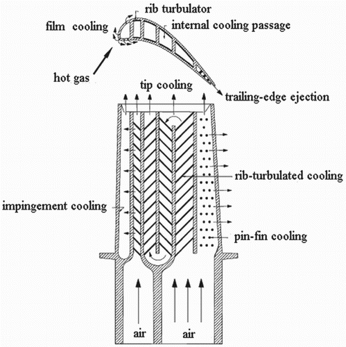
In order to achieve desirable performance at high temperature, the blades of modern gas turbines must be protected by the film cooling method and cooled internally by the compulsive convection. Figure shows the internal geometry of a gas turbine vane and blade, consisting of several straight ribbed rectangular channels. The consecutive channels are connected by 180 degree U-shaped bends. Ribs on the inner surface of the cooling passage can enhance forced convection and cooling performance. However, the existence of ribs leads to extra friction loss and pressure drop, compared with the smooth channel. Therefore, the guideline for the internal geometry optimization is to achieve larger heat transfer strength with less energy loss.
Figure 1. The blade internal cooling passages.
The overall friction and heat convection characteristics in the rib-mounted U-shaped passage are extensively studied. Chandra and Han (Citation1989), Ekkad and Han (Citation1997) and Han and Zhang (Citation1991) investigate the friction factor value and heat convection characteristics of passage with 45, 60 and 90 degree ribs together with an 180-degree bend. The result indicates that only the forced convection strength in the downstream straight passage is affected by the sharp turn and rib. Zhao and Tao (Citation1997) investigate the effect of different rib orientations of 45 and 60 degree ribs on heat convection strength in a U-shaped cooling passage. The result shows that rib orientation strongly influences the local and channel mass transfer abilities in the second passage. Jang, Chen, and Han (Citation2001) study the velocity vector and forced convection strength of a U-shaped tube with 60 degree ribs; the U-shaped bend and the angled rib of the channel have significantly impact on the Nusselt number and flow energy loss in the downstream passage. Al-Hadhrami and Han (Citation2003) investigate the rib orientation effect of 45 degree ribs on the Nusselt number distribution in U-shaped passage. The results indicate that the parallel ribs obtain higher heat convection strength compared with the crossed ribs. Chanteloup, Juaneda, and Bölcs (Citation2002) study the flow field in the channel with U-shaped turn and 45 degree ribs by PIV to visualize the streamline behind the ribs. The three-dimensional velocity measurements show the position of the vortices generated by the ribs while two streams of individual secondary flows are generated at the same time. Another study focusing on the flow field structure in U-shaped passage with 45 degree ribs by PIV of Elfert, Schroll, and Forster (Citation2012) demonstrates the vortices due to the corner of the U-shaped channel appear at the inlet of the downstream straight pass. Zhu, Gao, Li, Li, and Gong (Citation2015) numerically investigate the relation between flow field and forced convection strength through the U-shaped passage with angled ribs by vortex core visualization method. It is shown that both the forced convection strength and the secondary flows in the straight channel after the turn are affected by the upstream secondary flows. In addition, Yang, Han, Azad, and Lee (Citation2015) investigate the heat convection along the three-pass ribbed passage. It can be observed that the secondary flow entering the downstream passage is major reason of the variation between the heat convection strength before and after the bend.
More investigations focus on the U-shaped bend, which is an influencing factor for the forced convection in U-shaped passage. Mochizuki, Murata, and Fukunaga (Citation1997) experimentally study the heat transfer performance of 60 degree ribs and the friction characteristics of 30, 45, 60, 75 and 90 degree ribs in U-shaped channel. For different rib orientations, the results of 60 degree rib cases indicate similar Nu ratio distribution in the No. 1 channel but distinct in the No. 2 channel. After the first passage, the forced convection strength is highly influenced by the bend shape. Saha and Acharya (Citation2013) investigate the influence of bend shape on overall heat transfer performance, and suggest the symmetrical bulb configuration enhances the thermal performance factor by 41%. Siddique, Shevchuk, El-Gabry, Hushmandi, and Fransson (Citation2013) study the influence of bend cross-section width on the downstream heat convection strength and friction loss. It is shown that the overall heat convection strength reaches the highest when the width is 0.88 times the height. A similar conclusion is reached by Jenkins et al. (Citation2013) that the small width enhances the downstream heat convection strength in the second pass. Erelli, Saha, and Panigrahi (Citation2015) research the influence of different bend shapes on the forced convection performance and flow energy loss in a two-pass passage. It is shown that the heat convection strength in the downstream passage is in direct proportion to the secondary flow strength in the bend. Furthermore, the investigation by Lei, Li, Han, Zhang, and Moon (Citation2013) indicates that the guide vane between the two straight channels enhances the downstream heat convection strength and also reduces the friction loss in the whole passage.
According to the previous investigation of Mochizuki et al. (Citation1997), the forced convection performance in the first straight passage is similar for different rib orientations at a certain rib angle, but the downstream heat convection characteristics are strongly affected by the turn and its combined effect with rib orientation in both passes. In order to optimize the cooling performance of multiple-pass channel, visualization of secondary flows generation and interaction is indispensable to understand the coupling effect of rib orientation and U-turn on friction loss and cooling performance. However, the combined effect has not been systematically investigated with respect to secondary flow structure. Due to the challenge of flow measurement in the ribbed channel and the lack of a powerful 3-D visualization method, previous experimental investigations have not provided the whole three-dimensional structure of secondary flow in the U-shaped ribbed channel, but velocity distribution and direction on separate cross-sections.
This paper numerically studies the flow field structure evolution in a U-shaped passage with several rib configurations by the advanced vortex core visualization technology. Since the typical coolant Reynolds number range in turbofan engine is 30000, all the cases have the same Reynolds number of 30,000 to give consideration to both the high and low Reynolds number situations. The interaction between upstream secondary flow and newly formed flow structure in the downstream straight passage and the bend is analysed in a comprehensive 3D view. The relationship between cooling performance and secondary flow interaction is revealed, which contributes to the understanding of heat convection enhancement mechanism in a U-shaped passage with angled ribs. Based on the understanding the interaction between the secondary flow entering and exiting the bend, modified bend geometry is proposed to reduce the energy loss in the flow and enhance the cooling performance. The flow structure visualization and thermal performance analysis method could provide guidance and direction to enhance forced convection and reduce energy dissipation by optimizing the secondary flow in the U-shaped channel, leading to a balance in cooling performance and friction loss.
2. Numerical method
2.1 Physical model
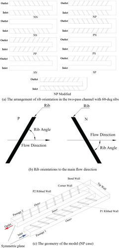
The geometry is modeled against the experimental work by Mochizuki et al. (Citation1997), and modified bend geometry is also numerically investigated. In this paper, the rib angle is fixed at 60 degree, since this experimental work has indicated this angle is a reasonable compromise of flow energy loss and heat convection performance. The different rib arrangements are demonstrated in Figure (a) and (b). Remarkably, modified bend geometry is proposed with a round corner at the bend entrance in junction with the outer wall, and the radius of the round corner is 44 mm. In the viewing direction from ribbed wall to the symmetric plane, the case is marked as ‘P’ since the rib orientation is in the counter-clockwise direction. Otherwise, it is regarded as ‘N’ for the negative direction. The smooth channel is named as ‘S’; and the cases with single smooth channel are used to investigate the interaction between different streams of secondary flow generated by the bend and that by either upstream or downstream ribbed channel. Figure (c) shows the naming of the numerical model surface. A symmetric plane boundary condition is employed to reduce the mesh scale in the calculation. The channel width and height are both 44 mm and the length between inlet and the tipwall is 440 mm. The rib height is 4 mm and the rib space is 44 mm. Identical with the experimental model, a space of 1 mm is set between the rib end and side wall.
Figure 2. Models of the two-pass channels (viewed from ribbed wall to symmetric plane). (a) The arrangement of rib orientation in the U-shaped channel with 60-deg ribs; (b) Rib orientations; (c) The geometry of the model (NP case).
2.2 Mesh
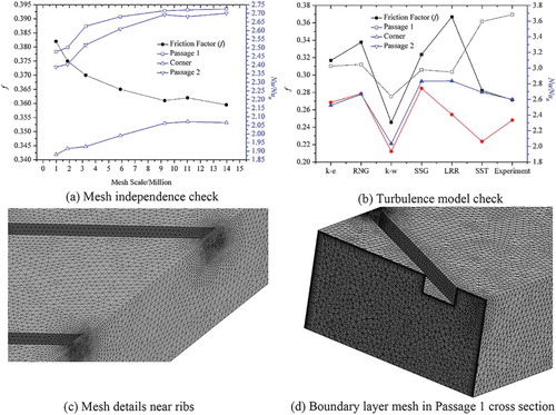
The unstructured mesh consists of tetrahedrons and prisms inflated from the wall boundary layers. The near wall region has 20 inflation layers with a growth ratio of 1.2. The Y+ value is guaranteed below 1. A mesh independence test is performed using the Shear Stress Turbulence (SST) turbulence model. The friction factor and regional averaged Nusselt number ratio curves show that the mesh independence has been achieved if the node number is larger than 9.27 million, which is shown in Figure (a). Therefore, the mesh with 9.27 million nodes and 20 inflation layers is adopted in this study. The details of mesh are shown in Figure (c) and (d).
Figure 3. Mesh independency check and mesh arrangement. (a) Mesh independence check; (b) Turbulence model check; (c) Mesh details near ribs; (d) Boundary layer mesh in Passage 1 cross section.
2.3 Boundary conditions and turbulence model
The SST turbulence model in CFX 14.0 is adopted in this study. The investigation by Walker and Zausner (Citation2007) has shown that the SST turbulence model is the best choice in simulating the flow and forced convection in the rectangular passage with 45-degree straight ribs. In addition, the SST model has also been usefully applied on a single pass channel study of Gao, Zhu, Liu, and Xu (Citation2016) with a reasonable match with experimental work. In order to identify the proper turbulence model for this study, six different turbulence models are compared. The result in Figure (b) confirms that the SST turbulence model is the best choice for the smallest discrepancy with experimental data. In this numerical research, incompressible ideal air is adopted, since the inlet Mach number 0.029 is much smaller than 0.3. The inlet velocity boundary condition is set as zero gradient to model the non-uniform velocity profile which develops along a straight smooth channel before the selected inlet of this numerical model. The inlet pressure of the channel was fixed at 1 atm and the air inlet temperature was 298 K. The inlet turbulent intensity is set at 5% and the mass flow rate is selected at the outlet targeting at Re = 30000. The no-slip wall condition and a constant temperature of 338 K are set for wall. The Root Mean Square (RMS) error is set at less than 10−5 for the convergence criterion.
2.4 Data reduction method
The dimensionless parameter Re is defined according to Equation (1).
(1)
| ρ: | = | density of air. |
| V: | = | velocity of air. |
| Dh: | = | channel hydraulic diameter. |
| µ: | = | dynamic viscosity. |
| k: | = | thermal conductivity. |
| q: | = | wall heat flux. |
| h: | = | heat transfer coefficient. |
| µ: | = | viscosity. |
| Cp: | = | isobaric heat capability |
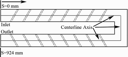
Nu is defined by Equation (2). Figure shows the centerline of the channel. Since the local bulk temperature Tb is not linearly increased along the centerline under the uniform-temperature wall boundary, so Tw–Tb is calculated by logarithmic mean temperature difference which is defined by Equation (6). Tw is the wall temperature. Tout and Tin is the outlet and inlet temperature of the control volume, respectively.
(6)
Nu0 is selected as the Nu in the smooth and straight pipe flow which is fully-developed turbulent and the tube is nonrotating. The Prandlt number which is defined by Equation (5) is set as 0.71.
Figure 4. The centerline axis of the channel for bulk means temperature and friction factor calculation.
According to the experimental work by Mochizuki et al. (Citation1997), the friction factor f is defined as:
(7)
Δp: the pressure drop through the whole passage.
L: the distance from the inlet to the outlet along the centerline axis, which is shown in Figure .
In addition, a non-dimensional thermal performance factor TF is defined in this study (Gee & Webb, Citation1980):
(8)
The friction factor of smooth straight channel f0 is calculated by Equation (9).
(9)
Velocity ratio is calculated as the ratio of the velocity component in cross-section plane and the flow velocity component in flow direction.
The Dean number is defined as below:
(10)
Where Rc is the curvature radius. The Dean number in this investigation is constant at 42420.
2.5 Vortex core method
The vortex core visualization method can display the position of the swirling flow and vortex structure, and there are several definitions of vortex core. Sahner, Weinkauf, and Hege (Citation2005) use λ2 definition for the visualization of flow around a cylinder. Ibaraki, Furukawa, Iwakiri, and Takahashi (Citation2007) use normalized helicity for the flow visualization in a centrifugal compressor. Laramee et al. (Citation2008) adopt texture-based method for the visualization of vortex in combustion chamber. Škerlavaj, Škerget, Ravnik, and Lipej (Citation2014) use Q-criterion for the view of free vortices. Kubacki, Rokocki, and Dick (Citation2014) also show the vortex in straight rotating cooling channel with 90-degree ribs by λ2 definition. The above investigations using vortex core method indicate that this method could directly show the whole vortex surface and provide important information on the evaluation of vortex and secondary flow.
According to the investigation of Jeong and Hussain (Citation1995), λ2 definition is recommended after comparison with the Q criterion and local-pressure-minimum definition. λ2 is the second largest real eigenvalues of the tensor S2 + Ω2, which is based on the acceleration tensor D:
(11)
(12)
(13)
Then: S + Ω = D, S2 + Ω2 = sym(D2)
The tensor S2 + Ω2 only has real eigen-values, and the region with λ2 < 0 is the vortex core.
3. Results and discussion
3.1 Numerical result validation
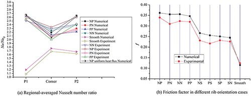
Against the experiment results by Mochizuki et al. (Citation1997), the discrepancy of the numerical simulation is checked. The Reynolds number is 30000 for both the experimental and numerical test. The ribbed wall of this U-shaped channel is divided into three parts: P1 ribbed wall, P2 ribbed wall and bend wall, shown in Figure (c). Both Passage 1 outlet and Passage 2 inlet are at the same coordination with the corner wall in flow direction. The comparison of region-averaged Nu ratio for the smooth channel and NN, NP, PN, PP passage with 60 degree ribs is shown in Figure (a). Notably, the experimental wall heating setup is neither ideal homogeneous temperature nor heat flux boundary. Given the low thermal conductivity of Bakelite channel material and thin metal sheet heating, homogeneous heat flux boundary should approximate the experimental setup. However, homogenous wall temperature boundary is more representative for the engine blade cooling channel and thus adapted as the wall boundary condition in this numerical study. Therefore, both homogeneous temperature and heat flux wall boundary conditions are evaluated for the modified NP case, it is found the impact of different boundary conditions on the secondary flow structure and Nu distribution is negligible. The numerical results agree with the experimental data in trend with minor discrepancy. The relative discrepancy is about 7% for straight part of the smooth channel, 4% for the turn. The relative discrepancy is small in the straight channel but large in the bend region for the ribbed channel. The largest relative discrepancy is about 9.4% for the 60 degree PP case. Furthermore, Figure (b) compares the friction factor between experimental and numerical results. The friction factor discrepancy is small except for PN and PS cases. The largest discrepancy of 14.6% is found for PN case and 17.7% for PS case, but the discrepancy of other cases are no larger than 13%. The relative large friction factor discrepancy of PS and PN cases may be caused by the limitation of turbulence model on the simulation of the energy dissipation in the certain secondary flow interactions. This validation suggests that this numerical model is capable of simulating the forced convection and 3-D flow in the U-shaped channels.
Figure 5. The experimental validation of numerical model. (a) Domain-averaged Nu ratio; (b) Friction factor in different rib orientation cases.
3.2 Heat convection characteristics
3.2.1 SN, SP, NS and PS arrangement
Figure shows the Nu ratio contour on a two-pass channel with one smooth and one ribbed passage so that the impact of rib channel and bend on the cooling performance can be evaluated separately. It is indicated in Figure (a) that the heat convection capacity of Passage 1 and the bend region are similar for SN and SP cases, but difference exists in Passage 2. The entrance effect is evident within the length of one channel width and larger Nu ratio is obtained because of the thin thermal boundary layer. The enhanced thermal performance in the corner is apparently larger than the smooth one, because of the Dean vortex generated by centrifugal force. The regional-averaged Nu ratio in Passage 2 is 2.17 and 2.023 for the SN and SP channel, respectively. It suggests the bend-induced secondary flow has improved the heat transfer at the first rib for the SP case, compared with the SN case. At the inlet of Passage 2, the Nu ratio in the first few ribs of SP channel is higher than that of SN channel but the value in the downstream channel of SN is larger. The secondary flow developed at the bend is suppressed by the first rib in the Passage 2.
Figure 6. Nu ratio distribution with one ribbed straight passage (Re = 30000) (a) SN and SP channel; (b) NS and PS channel; (c) Smooth channel.
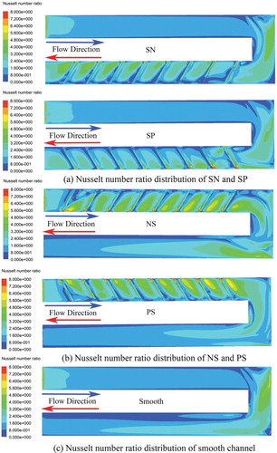
Meanwhile, it shows in Figure (b) that improved heat transfer strength can be observed in NS and PS cases, since the smooth Passage 2 taking advantage of the bend-induced secondary flow has better thermal performance than the smooth Passage 1. The Nu ratio contour for the smooth 2 pass channel is illustrated in Figure (c), which suggests the bend can enhance the heat transfer within and after the bend. The Nu ratio in the bend region decreases along the main flow direction in PS channel and it is facing a decrease-increase trend in NS channel. For the smooth Passage 2, the high Nusselt number region for NS channel is larger than that in PS channel, while the large Nusselt number region is continuous around the bend for the NS case. A region of large Nusselt numbers initializes at the top right corner of the bend, and stretches two thirds of Passage 2. As a result, the NS channel has better heat transfer performance in Passage 2, which is significantly higher than the case of SN or SP. In addition, the alternation of the Nu ratio contour in the bend can be observed after the ribbed Passage 1. Those interesting phenomena are caused by the interaction between the parallel secondary flows near the bend which will be investigated in a later section.
3.2.2 Comparison of NN, NP PN and PP arrangement
It can be observed in Figure that the contour of Nu ratio of the channel with two ribbed straight passages. Overall, the heat transfer capacity is higher in Passage 1 compared with that in Passage 2. In Passage 1, the Nusselt number ratio in P-type rib orientation cases are relatively higher than those in N-type in the last three rib spaces near the bend region. However, Nu ratio values in the low Nu ratio region of NN and NP channels are larger than those of PN and PP cases. For the P-type cases, the Nu ratio of PN case is enhanced in the region between the last rib and the bend than that in PP case. However, the Nusselt number ratio distribution of NP and NN cases, as well as NS case in Figure , are similar in the sharp turn region where the Nu ratio distribution is mainly determined by the rib orientation in Passage 1. Meanwhile, it can be seen that a sliced long low heat convection strength region exist in the PN and PP cases. In the PP case, this region is close to the tip wall and its length is about 2Dh. In the PN case, this region is parallel to the tip wall with a relatively large distance to the tip wall and has frontiers with the low Nu ratio region near the exit of the bend. In Passage 2, the upstream flow becomes the major influencing factor of local heat transfer rather than the local rib orientation. The low Nusselt number ratio region area (colored in blue) of NN and NP cases is smaller than that of the PP and PN cases. The area sequence of low Nusselt number ratio region is PP > PN > NN > NP. Therefore, the Nusselt number ratio distribution is mainly influenced by the rib orientation in Passage 1 together with the bend direction. The influence of rib orientation in Passage 2 is smaller but cannot be ignored.
Figure 7. Nu ratio distribution with two ribbed straight passages (Re = 30000).
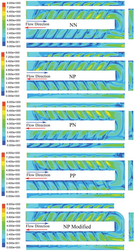
In addition, the Nu ratio on the outer sidewall can be seen in Figure . The Nu ratio contour on the outer wall of Passage 1 and the tip wall are similarly higher for the NN, NP and NP modified channel. Because the rib-generated local secondary flows develop parallel to the rib and sweep the outer wall, a higher Nusselt number is expected for the N-type channel 1. It suggests the ribs enhance forced convection in the rib space and the sidewall. However, the rib has less influence on the other side wall of Passage 1. Smaller areas for high Nusselt number are limited to the rib height on the outer wall of the P-type Passage 1. In the bend region, N-type Passage 1 results in a higher Nusselt number ratio on the bend bottom and outer wall. In Passage 2, the Nu ratio contour has a weaker but similar pattern with that in Passage 1 of the opposite rib orientation after the first two ribs, since the corner generated second flow has strong influence in the first few ribs in Passage 1.
Figure (a) shows the domain-averaged Nu ratio along the flow direction and the overall channel friction factor value of the nine cases. The sequence of domain-averaged Nusselt number ratio is NP modified > NP > PN > NN > PP > NS > PS > SN > SP >smooth channel. Without modification to the bend geometry, the NP case has the higher heat transfer performance than the PN case, and cross-rib configuration is preferred over the parallel rib in two passages. N-type rib wall has better thermal performance than P-type, if the other passage is smooth channel. Furthermore, it is confirmed that the smooth wall in Passage 2 has an obvious advantage over the smooth wall in Passage 1, because the secondary flow produced by the Passage 1 and the bend can enhance heat convection significantly in the downstream smooth channel. The modified NP case has a higher Nusselt number than the NP case at the bend exit, as shown in Figure ; it is confirmed by the quantitatively comparison in Figure (a). At the same time, the NP modified channel also has the largest friction factor than the others. There are slight differences among NN, NP, PN and PP in friction factor; the same trend is observed in NS, PS, SN and SP cases. The P-type rib in Passage 1 and N-type rib in Passage 2 generates smaller friction loss than the other two cases.
Figure 8. The overall heat convection strength of 9 different rib orientations. (Re = 30000) (a) Area-averaged Nu ratio and friction factor; (b) Thermal performance factor of 9 different rib orientations.
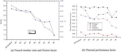
Figure (b) shows that thermal performance factor (TF) values for the three parts and the entire channel; a higher thermal performance factor is preferred for better cooling effect with less friction loss. The sequence of thermal performance factor is NP > PN > NS > PP > NN > PS > SN > SP for the whole channel without the modification of the bend geometry. Furthermore, the individual thermal performance factors in Passage 1, bend and Passage 2 are also indicated in Figure (b) to investigate the heat transfer capability for each part of the channel. In Passage 1, thermal performance factor is mainly determined by the existence of a ribbed wall. The ribbed channel has a larger thermal performance factor than the smooth one, which is also influenced by the effect of local rib orientation and the bend. In the corner region, the thermal performance factor sequence is NN > PP > PN > SN > NS > NP > PS > SP. It is shown that the parallel orientated rib (NN, PP) in the two straight channels has larger heat transfer ability than the crossed orientation one. However, the impact on the whole channel performance is limited for the small wall area of the bend. In Passage 2, the sequence is NP > SP > PS > NS > NN > SN > PN > PP. Obviously, the crossed rib orientation in two straight channels is better than that of the parallel rib orientation. Further improvement of cooling performance can be achieved by the modified bend geometry for the optimized NP rib configuration and secondary flow control. The modified bend can reduce the energy loss and improve the heat convection performance at the same time. Thereby, significantly higher thermal factors are found at the bend and in Passage 2, in comparison of the existent design of NP case.
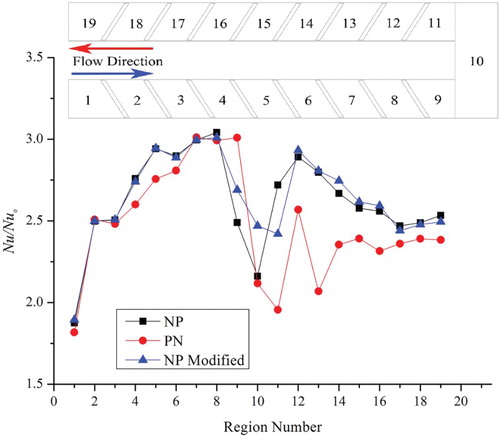
To compare the heat transfer characteristics of PN, NP and modified NP cases, the regional Nu ratio curve along the flow direction is displayed in Figure . The whole ribbed wall is divided into 19 parts: the 9th and 11th region are the wall between the rib and the corner wall plane; the 10th region is the bend wall and the other regions consist of the space wall and the corresponding rib (Passage 1) in downstream direction or the upstream rib (Passage 2). The NP case has the slightly larger regional-averaged Nusselt number ratio in Passage 1 at regions 5 and 9, but it is smaller in the 9th region just before the bend. Similar performance is found in region 10 (the bend) for both unmodified cases. However, the regional-averaged Nusselt number ratio of the NP case is apparently larger than that of the PN case in Passage 2, i.e. since the 11th region. In particular, the Nu ratio curve of the PN case in the 11th region is much lower than that of the NP case. Due to excellent performance in Passage 2, the NP case outperforms the other eight configurations in heat transfer strength. Furthermore, the modified NP case has slightly higher thermal performance in Passage 1 and Passage 2 than the existent NP case, while the improvement in the bend region is evident. Although the existent NP case outperforms in the 11th region, the large area in the bend contributes to the higher overall performance.
Figure 9. Regional-averaged Nu ratio in streamwise direction (Re = 30000).
3.3 Flow field structure and influence on heat convection
The heat convection characteristics of Passage 1 are similar, which is less affected by the downstream flow condition. In comparison, the combined influence of the secondary flows in the upstream flow field strongly affects the forced convection strength along the downstream passage. Therefore it is important to investigate the flow field in the whole U-shaped channel to illustrate the intrinsic relation between forced convection and rib orientation. The investigation of Han, Dutta, and Ekkad (Citation2012) indicates that the secondary flows are located in several different positions of the flow field. The first position is between the parallel ribs and the other one is above the rib. In this study, the secondary flows in the whole flow field will be investigated by the emergent flow visualization technique of vortex core.
3.3.1 Main flow secondary flows
The secondary flows generated in the bend and its influence on the flow field in Passage 2 with N-type and P-type rib orientation are shown in Figure , respectively. Without the rib in Passage 1, the overall local turbulence kinetic energy is low without small strips of secondary flow. Two streams of secondary flow are initialized at the outlet of the Passage 1. The first one is generated around the corner wall edge and it flows along the corner wall then pours into the Passage 2 with high strength and turbulent kinetic energy, and it is marked as the Bend Generated Secondary Flow. The other is produced when the flow comes to the exit of the bend; it is named as the P2 Corner Generated Secondary Flow. Depending on the rib orientation in the downstream passage, it shows different strength along the outer wall of Passage 2. In the SN case, the size of this secondary flow is small and its initial position is just the same as the local Main Flow Secondary Flow. Its rotation direction is the same as the P2 Main Flow Secondary Flow. It can be observed that the Corner Generated Secondary Flow moves towards the centerline position and is quickly dissipated. On the other hand, the sweeping area of the Corner Generated Secondary Flow is bigger for the SP case because of its opposite rotation direction with the local one in the downstream passage. This secondary flow survives more than half the length of Passage 2, but it delays the formation of the local Main Flow Secondary Flow. Benefiting from the independent development, the energy dissipation rate is slower for the Corner Generated Secondary Flow. Because the formation process of the Main Flow Secondary Flow in the second passage is less disturbed, the turbulence kinetic energy level is higher in the SN case than that in the SP case. As a result, the Nu ratio of Passage 2 in the SN case is larger than that of the SP case.
Figure 10. Secondary flow in SN and SP channel (Re = 30000; Left: SN; Right: SP).
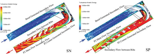
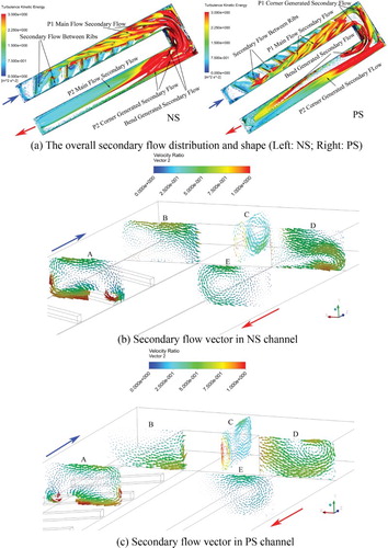
Figure shows the solo effect of rib orientation in Passage 1 on the flow field. Due to the opposite rotating direction for the Main Flow Secondary Flow in the first straight channel, its location is distinct in the bend region. It sweeps the whole channel in the bend for the NS case, while it is split for the PS case. It can be treated as a pair of secondary flows with different rotation direction (see secondary flow vector on cross section C in Figure (c)), which does not suppress the rotating energy reciprocally. Meanwhile, the P1 Main Flow Secondary Flow is split before entering the bend for the PS case, and the same rotation direction leads to loss of secondary flow momentum. The distinct secondary flow structure in the bend has an obvious impact on Passage 2. In Passage 2, two streams of secondary flow can be observed. In the NS case, the one near the outer wall is much larger. It covers more area than the P2 Corner Generated Secondary Flow. The secondary flow delivered from the bending has strong interaction with the P2 Corner Generated Secondary Flow. The secondary flow suddenly dies out near the second rib from the Passage 2 entrance. For the PS case, the P1 Corner Generated Secondary Flow joins the P2 Corner Generated Secondary Flow and then becomes the only dominant secondary flow in Passage 2. Therefore, Figure clearly demonstrates that the N-type rib orientation which is opposite to the bend direction can transport more turbulence energy into the downstream passage and provide larger heat transfer capability.
Figure 11. Secondary flow in NS and PS channel (Re = 30000). (a) The overall secondary flow distribution and shape (Left: NS; Right: PS); (b) Secondary flow vector in NS channel; (c) Secondary flow vector in PS channel.
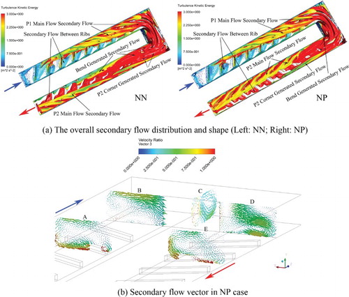
It is indicated in Figure that the coupling influence of N-type rib orientation in Passage 1 and the bend on the flow field in Passage 2 with N-type and P-type orientation ribs respectively. For Passage 1 and the bend, the secondary flow of N-orientation rib is similar with that in NS case (see Figure ). The bend structure forces the P1 Main Flow Secondary Flow to turn right which largely enhances the turbulence kinetic energy value of it. However, the flow field for NP case in Passage 2 has the preferred secondary flow interaction for heat transfer, different from that in NS case or NN case. The P2 Main Flow Secondary Flow of the N-type orientation locates near the inner wall while it is at the other side of the passage for the P-type rib orientation. The vortices pair with opposite rotation direction in the bend transports more rotating secondary flow energy into Passage 2, confirmed by cross-section velocity plots shown in Figure (c); the strong P2 Corner Generated Secondary Flow can be found at the corner. As a result, the coupling effect of the several streams of upstream secondary flow forms one dominant secondary flow at the entrance of the Passage 2. Compared with the NN case, P2 Corner Generated Secondary Flow has been kept weaken along the flow direction in the NP case. However, the P2 Main Flow Secondary Flow of NP case integrates Bend Generated Secondary Flow, leading to stronger than that in the NN case. For the NN case, the dominant secondary flow at the Passage 2 entrance has the negative impact on the P2 Main Flow Secondary Flow for the opposite rotating direction. The size and the turbulence kinetic energy are both larger for the NP case than those of the NN case, which indicates that the NP arrangement has larger heat transfer enhancement potential in Passage 2. The disturbance strength in near-wall region of Passage 2 is also largely enhanced compared with that in the first straight passage.
Figure 12. Secondary flow in NN and NP channel (Re = 30000). (a) The overall secondary flow distribution and shape (Left: NN; Right: NP); (b) Secondary flow vector in NP case.
It is shown in Figure that the combined effect of P-type rib orientation in Passage 1 and the bend on the flow field in Passage 2 which has N-type and P-type orientation ribs, respectively. The secondary flow shape and distribution in Passage 1 is similar for PN case and PP case, as well as PS case in Figure . Another stream flows along the corner wall and maintains high turbulence kinetic energy. Since limited secondary flow energy is transferred to Passage 2 for the combination of P-type ribbed wall in Passage 1 and the right turning bend, the P2 Corner Generated Secondary Flow is the primary flow structure at the entrance of Passage 2. In the PN case, the primary one has the same rotation direction as the local main flow secondary flow in N-type Passage 2 and enhances heat transfer by augmenting the P2 Main Flow Secondary Flow, while it suppresses the P2 Main Flow Secondary Flow development in the PP case. In the PP case, the P2 Corner Generated Secondary Flow significantly reduces the turbulence kinetic energy in Passage 2 than that in the PN case. The reduction in P-type rib orientation case will be more obvious because that the secondary flow produced by the bend is located just at the location of the Main Flow Secondary Flows, which makes the forced convection strength reduced in the downstream Passage than that of the PN case. Therefore, the PN case has better thermal performance than the PP case.
Figure 13. Secondary flow in PN and PP channel (Re = 30000). (a) The overall secondary flow distribution and shape (Left: PN; Right: PP); (b) Secondary flow vector in PN case.
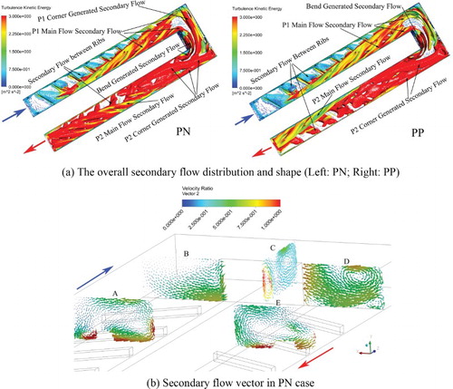
Although both the P2 Corner Generated Secondary Flow and P2 Main Flow Secondary Flow have the same rotating direction for both NP and PN cases, the former one has a different impact on the thermal performance in Passage 2. Because the P-type rib orientation in Passage 1 leads to the distinct rotation direction for the P2 Corner Generated Secondary Flow, cross rib orientation (either NP or PN) is preferred. For the PN case, the dominant P2 Corner Secondary Flow near the symmetric plane flows towards the inner wall and dissipates slowly in both cases, but it does not directly accelerate the P2 Main Flow Secondary Flow formation. Therefore, NP case has the better thermal performance in Passage 2.
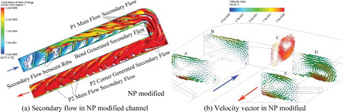
Based on the above investigation, bend shape modification could reduce the pressure loss and/or improve thermal performance. Since no preferred secondary flow is generated from P1 corner, the square corner is modified into a round shape. This modification aims to reduce the pressure by avoiding sharp flow turning, and delivers more secondary flow energy from Passage 1 into the bend region. Figure (a) shows the secondary flow structure is stronger in the bend than that in the NP case (see Figure (a)). It is confirmed by velocity flow in cross-section C, see Figure (b). Moreover, P2 Main Flow Secondary Flow structure sweeps the whole channel in Passage 2. The higher turbulence energy and the stronger sweeping effect of the secondary flow eventually lead to the improved thermal performance in the bend and Passage 2, illustrated quantitatively in Figure .
Figure 14. Secondary flow in NP modified channel (Re = 30000). (a) Secondary flow in NP modified channel; (b) Velocity vector in NP modified channel.
3.3.2 Secondary flow between ribs
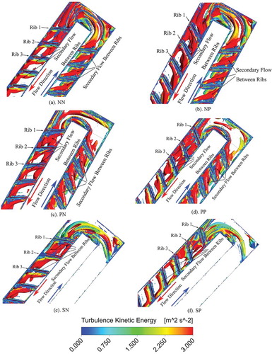
In the downstream region of the bend, the flow field between ribs will also be affected by the secondary flow energy from the upstream channel. The main flow disturbance may upset the regularly separate-reattach process and the transverse flow. The shape of near wall secondary flow is in Figure . The vortex core criterion was set as λ2 < −0.0008(−λ2)max to hide the secondary flow with low energy. It is indicated that the secondary flow between ribs is similar for both N-type and P-type orientation in Passage 1, which is the original state of secondary flow without influence by upstream flow. However, the upstream flow causes deformation of the near wall ones in downstream passage. In both NN and PP cases, the deformation of secondary flow is obvious before rib 3. In Passage 2 of NP and PN cases, it is less affected by the upstream flow field. The secondary flow between rib 1 and rib 2 obviously inflates and the one after rib 2 has reduced size in the PN case. The size of the secondary flow in the same position of the NP case is larger than that of the PN case since the rib 2 along the flow direction. The influence of bend on secondary flow between ribs can be seen in Figure (e) and Figure (f). It is shown that the SN case is less influenced by the upstream flow than that of the SP case. In the SP case, the secondary flow between ribs recovers to its normal shape after rib 3. In comparison, only slight deformation can be seen on the secondary flow between ribs 2 and rib 3. Furthermore, the influence of upstream flow can also be illustrated by the turbulence kinetic energy level on the surface of secondary flow in near-wall region. The turbulence kinetic energy is larger for cross rib orientation (either NP or PN) than that in parallel rib orientation. The deformation of near-wall secondary flow in the Passage 2 indicates that the separate-reattach process is disturbed, which reduces the heat transfer enhancement effect of rib. At the same time, the rib orientation in several cases leads to strong dissipation of upstream secondary flow. Therefore, the enhancement influence of upstream region on local forced convection is reduced, leading to the reduced Nusselt number in Passage 2.
Figure 15. Secondary flow between ribs (Re = 30000); λ2 < −0.0008(−λ2)max). (a) NN; (b) NP; (c) PN; (d). PP; (e) SN; (f) SP.
3.4 The relation between secondary flow and heat convection
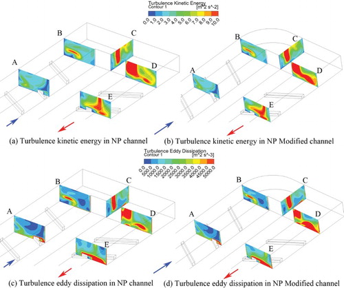
Figure shows the turbulence kinetic energy contour and eddy dissipation contour on five cross-sections. The cross-section A and E locate at the position away from inlet plane of 306 mm and the distance between inlet and cross-section B and D is 396 mm. The cross-section C is in the middle of bend. It is indicated that the high turbulence kinetic energy and eddy dissipation are both induced by the rib disturbance and the interaction among nearby parallel secondary flows in the main flow region, whose energy dissipates quickly. On plane D, the area of high value of these two parameters is enlarged, since the modified P1 Corner reduces the energy loss of secondary flow flowing through the bend.
Figure 16. Turbulence kinetic energy and eddy dissipation in NP and NP Modified channel (Re = 30000). (a) Turbulence kinetic energy in NP channel; (b) Turbulence kinetic energy in NP Modified channel; (c) Turbulence eddy dissipation in NP channel; (d) Turbulence eddy dissipation in NP Modified channel.
For the channel with angled ribs, the separate-reattach process caused by angled ribs in near-wall region could reduce the growth of boundary layer and enhance the local turbulence strength, which directly raises the local heat transfer strength. Meanwhile, it also offers rotation velocity to the main flow secondary flow. Therefore, the mass transfer strength in the direction which is perpendicular to the flow direction is enhanced. For a two-pass ribbed passage, the upstream flow structure is only determined by rib parameters in Passage 1. However, in the downstream channel, the secondary flows are strongly influenced by the upstream flows, which are all located in main flow region. Therefore, according to the former analysis in this study, two guidelines for Passage 2 heat transfer enhancement are listed below:
The first key factor is to transport disturbance energy from Passage 1 and the bend region to Passage 2 as much as possible without weakening the local secondary flow in Passage 2. The square-edged bend can produce extra secondary flow at the entrance of Passage 2, which enhances the forced convection. When the rib orientation in Passage 1 is opposite to the bend direction, it shows a positive effect on heat convection enhancement in downstream straight passage. In this case, the N-type rib arrangement is better than P-type rib in Passage 1. In the downstream straight channel, the Main Flow Secondary Flow in Passage 2 which swirls in the same direction with the dominant upstream one will reduce energy dissipation, therefore the P-type rib arrangement is preferred in the case of the N-type rib orientation in Passage 1.
Another key factor of heat transfer enhancement in Passage 2 is to reduce the adverse influence of upstream flow on near wall secondary flow. The disturbance in main flow region due to the strongly interaction between local secondary flow and upstream secondary flow will upset the regular separate-reattach movement and the transverse flow, which causes the reduced heat transfer performance. In general, the near wall flow in NP case undergoes the least negative impact and maintains the largest turbulence kinetic energy. The PP case experienced the largest negative influence from the upstream flow and its turbulence kinetic energy is also largely reduced and dissipated.
4. Conclusion
The influence of rib orientation in a U-shaped channel on local heat transfer and friction loss has been numerically investigated by the vortex core method. It is shown that the forced convection characteristics in the downstream straight channel are affected by the coupling effect of rib orientation and bend. Based upon this numerical study, some essential conclusions are listed below:
Firstly, the rib parameters of the rib in Passage 1 are the only factor that influences the local flow field. The main flow secondary flow of the N-type rib orientation is near the outer wall and the one generated by P-type rib orientation is near the inner wall with the opposite rotating direction. The turbulence kinetic energy distribution is similar for N-type and P-type but the case with N-type rib orientation is not obviously weakened in the bend. The secondary flow in Passage 1 of P-type rib orientation case is separated at the exit of the first straight passage and is quickly dissipated. As a result, N-type rib orientation provides more disturbances to the downstream Passage 2 than that of P-type in Passage 1.
Secondly, the secondary flows produced in the U-shaped bend consist of two parts. The first one is generated at the entrance of bend and flows along the corner wall and then flows into Passage 2. The other part is generated at the corner of tip wall and Passage 2 outer wall. The latter usually flows along the outer wall of Passage 2 but may be pulled to the inner wall.
Thirdly, the upstream flow has distinct influence on the flow field in Passage 2. For the NN and NP cases, as the strength of secondary flow along the tip wall in Passage 2 is much smaller than that of Passage 1 secondary flow, the P-type rib orientation can reduce the friction factor in the interaction of secondary flow. This enhances the growth of the Main Flow Secondary Flow in Passage 2. In Passage 2, the upstream flow strongly affects the secondary flow for the first 3 ribs, which causes the deformation of secondary flow between ribs and reduction of turbulence kinetic energy. The crossed rib orientation in the two-pass channel can reduce the negative impact on upstream flow on near wall secondary flow and maintain the turbulence kinetic energy of near wall secondary flow.
Fourthly, two guidelines for the optimized interaction between secondary flows in a U-shaped ribbed channel are proposed. Since the upstream secondary flow may suppress the downstream secondary flow in the main flow region, the first guideline for the rib arrangement in Passage 2 is to transport as much disturbance energy into Passage 2 without seriously weakening the local ones. The other key suggestion is to reduce the negative impact of upstream flow on near wall secondary flow in Passage 2.
Finally, based on the understanding of interaction of secondary flow near the bend, a modified bend geometry is proposed for the case of NP rib orientation and the numerical study shows 9% thermal performance gain over the existent NP case. Since no influencing secondary flows have been produced at the corner of P1 outer wall and the bend entrance, a fillet transition can obviously reduce the pressure loss. Furthermore, the round corner can deliver more secondary flow energy into the bend and Passage 2, resulting in higher thermal performance in the bend.
In this paper, secondary flow interaction is visualized and analysed in a comprehensive 3D view. This numerical study proposes the mythology of optimizing forced convection within constrained geometry via secondary flow control. The usability of this approach is exampled by the enhanced thermal performance in ribbed passages with the modified bend shape, but this method is not limited to blade cooling application. Further work could be the optimizing of other bend geometrical parameters for even better thermal performance and parameter study for the modified bend geometry.
Disclosure statement
No potential conflict of interest was reported by the authors.
ORCID
Qingfeng Xia http://orcid.org/0000-0002-7487-7433
Additional information
Funding
- Al-Hadhrami, L., & Han, J. (2003). Effect of rotation on heat transfer in two-pass square channels with five different orientations of 45° angled rib turbulators. International Journal of Heat and Mass Transfer, 46(4), 653–669. doi: 10.1016/S0017-9310(02)00325-3
- Chandra, P. R., & Han, J. C. (1989). Pressure drop and mass transfer in two-pass ribbed channels. Journal of Thermophysics and Heat Transfer, 3(3), 315–320. doi: 10.2514/3.28787
- Chanteloup, D., Juaneda, Y., & Bölcs, A. (2002). Combined 3-D flow and heat transfer measurements in a 2-pass internal coolant passage of gas turbine airfoils. Journal of Turbomachinery, 124(4), 710–718. doi: 10.1115/1.1506176
- Ekkad, S. V., & Han, J. C. (1997). Detailed heat transfer distributions in two-pass square channels with rib turbulators. International Journal of Heat and Mass Transfer, 40(11), 2525–2537. doi: 10.1016/S0017-9310(96)00318-3
- Elfert, M., Schroll, M., & Forster, W. (2012). PIV measurement of secondary flow in a rotating Two-pass cooling system with an improved sequencer technique. Journal of Turbomachinery, 134, 0310013. doi: 10.1115/1.4003222
- Erelli, R., Saha, A. K., & Panigrahi, P. K. (2015). Influence of turn geometry on turbulent fluid flow and heat transfer in a stationary two-pass square duct. International Journal of Heat and Mass Transfer, 89, 667–684. doi: 10.1016/j.ijheatmasstransfer.2015.05.081
- Gao, T., Zhu, J., Liu, C., & Xu, J. (2016). Numerical study of conjugate heat transfer of steam and Air in high aspect ratio rectangular ribbed cooling channel. Journal of Mechanical Science and Technology, 30(3), 1431–1442. doi: 10.1007/s12206-016-0251-1
- Gee, D. L., & Webb, R. L. (1980). Forced convection heat transfer in helically rib-roughened tubes. International Journal of Heat and Mass Transfer, 23(8), 1127–1136. doi: 10.1016/0017-9310(80)90177-5
- Han, J. C., Dutta, S., & Ekkad, S. (2012). Gas turbine heat transfer and cooling technology (2nd ed.). Boca Raton: CRC Press.
- Han, J. C., & Zhang, P. (1991). Effect of rib-angle orientation on local mass transfer distribution in a three-pass rib-roughened channel. Journal of Turbomachinery, 113(1), 123–130. doi: 10.1115/1.2927730
- Ibaraki, S., Furukawa, M., Iwakiri, K., & Takahashi, K. (2007). Vortical flow structure and loss generation process in a transonic centrifugal compressor impeller. Paper presented at the proceedings of the ASME turbo expo 2007, Montreal, Canada.
- Jang, Y. J., Chen, H. C., & Han, J. C. (2001). Computation of flow and heat transfer in two-pass channels with 60 deg ribs. Journal of Heat Transfer, 123(3), 563–575. doi: 10.1115/1.1371931
- Jenkins, S. C., Zehnder, F., Shevchuk, I. V., von Wolfersdorf, J., Weigand, B., Schnieder, M. (2013). The effects of ribs and tip wall distance on heat transfer for a varying aspect ratio two-pass ribbed internal cooling channel. Journal of Turbomachinery, 135, 0210012.
- Jeong, J., & Hussain, F. (1995). On the identification of a vortex. Journal of Fluid Mechanics, 285, 69–94. doi: 10.1017/S0022112095000462
- Kubacki, S., Rokocki, J., & Dick, E. (2014). Hybrid RANS/LES of flow in a rib-roughened rotating channel. Paper presented at the Proceedings of ASME Turbo Expo 2014, Dusseldorf, Germany.
- Laramee, R. S., Erlebacher, G., Garth, C., Schafhitzel, T., Theisel, H., Tricoche, X., Weiskopf, D. (2008). Applications of texture-based flow visualization. Engineering Applications of Computational Fluid Mechanics, 2(3), 264–274. doi: 10.1080/19942060.2008.11015227
- Lei, J., Li, S., Han, J., Zhang, L., & Moon, H. (2013). Heat transfer in rotating multipass rectangular ribbed channel with and without a turning vane. Journal of Heat Transfer, 135(4), 041903. doi: 10.1115/1.4023040
- Mochizuki, S., Murata, A., & Fukunaga, M. (1997). Effects of rib arrangements on pressure drop and heat transfer in a rib-roughened channel with a sharp 180 deg turn. Journal of Turbomachinery, 119(3), 610–616. doi: 10.1115/1.2841165
- Saha, K., & Acharya, S. (2013). Effect of bend geometry on heat transfer and pressure drop in a two-pass coolant square channel for a turbine. Journal of Turbomachinery, 135(2), 319–329.
- Sahner, J., Weinkauf, T., & Hege, H. (2005). Galilean invariant extraction and iconic representation of vortex core lines. Paper presented at the EUROGRAPHICS – IEEE VGTC symposium on visualization, Berlin, Germany.
- Siddique, W., Shevchuk, I. V., El-Gabry, L., Hushmandi, N. B., & Fransson, T. H. (2013). On flow structure, heat transfer and pressure drop in varying aspect ratio two-pass rectangular channel with ribs at 45°. Heat and Mass Transfer, 49(5), 679–694. doi: 10.1007/s00231-013-1111-5
- Škerlavaj, A., Škerget, L., Ravnik, J., & Lipej, A. (2014). Predicting free-surface vortices with single-phase simulations. Engineering Applications of Computational Fluid Mechanics, 8(2), 193–210. doi:doi: 10.1080/19942060.2014.11015507
- Walker, D., & Zausner, J. (2007). RANS evaluations of internal cooling passage geometries: Ribbed passages and a 180 degree bend. Paper presented at the ASME turbo expo 2007, Montreal, Canada.
- Yang, S., Han, J., Azad, S., & Lee, C. (2015). Heat transfer in rotating serpentine coolant passage with ribbed walls at low Mach numbers. Journal of Thermal Science and Engineering Applications, 7(1), 11013. doi: 10.1115/1.4028905
- Zhao, Y. C., & Tao, Q. W. (1997). Effect of rib angle orientation on local mass transfer distribution around sharp 180 deg turn with rib-turbulators mounted in entire two-pass channels. Heat and Mass Transfer, 32(5), 325–332. doi: 10.1007/s002310050129
- Zhu, J., Gao, T., Li, J., Li, G., & Gong, J. (2015). Numerical investigation of secondary flow vortex core structure in the two-pass rectangular channel with 45° ribs. Paper presented at the proceedings of ASME turbo expo 2015, Montreal, Canada.