
ABSTRACT
Poor performance in the condensers in power plants and chemical plants is due to the fact that condensed water is deposited on the heat transfer pipes. The dynamics of condensed water droplets forming on the surface of heat transfer pipes have a significant effect on the heat transfer efficiency of heat exchangers. In the present study, a numerical approach using a coupled level-set and volume of fluid (CLSVOF) method was adopted to investigate the impact of water droplets on cylindrical pipes. The numerical model was verified by an experiment, and both sets of results showed qualitative and quantitative agreements. The effects of the surface wettability, impact velocity and relative size of the droplet to the pipe on the droplet impact dynamics are systematically investigated. Moreover, the regularities of the contact area between the liquid and the pipe during the impacting process as well as the volume of residual liquid remaining on the pipe post-impact are also analyzed; these two parameters are the key factors which affect the heat transfer efficiency of heat transfer pipes, and they cannot be acquired very accurately using experiments.
Subject classification codes:
1. Introduction
Water vapor condenses into water droplets when it comes into contact with a cold surface. This phenomenon is well known in heat exchangers, and is very common in power plants and chemical plants. Condensed water droplets impact on heat transfer pipes due to the effect of gravity, and typical dynamic behaviors during this process include impacting, spreading, retracting and rebounding. The study of the dynamics of droplets impacting on cylindrical surfaces is of great importance for understanding the resulting heat transfer deterioration in heat transfer pipes.
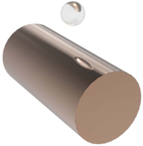
The process of droplets impacting on heat transfer pipes can primarily be simplified to the process of droplets impacting on solid cylinders, which has been extensively investigated for decades. A schematic drawing of this process is presented in Figure . With the development of high-speed camera technology, it has become possible to record detailed information about the droplet impacting process. Furthermore, with the advances in the field of numerical computation, the impacting process can also be simulated using computational fluid dynamics (CFD). Hung and Yao (Citation1999) studied the effect of impact velocity and wire size on the droplet impacting phenomenon and generated three models. In addition, they obtained a non-dimensional regime map for classifying these models and predicting the size of the falling droplets within the experimental limits. Pasandideh-Fard, Bussmann, Chandra and Mostaghimi (Citation2001) simulated center and off-center droplet impacts on a cylindrical tube using an extended 3-D Eulerian model. They also used the numerical model to explore the effect of tube size on the capabilities of the remaining liquid post-impact. Lorenceau, Clanet, and Quéré (Citation2004) and Lorenceau, Clanet, Quéré, and Vignes-Adler (Citation2009) studied the capturing capability of cylindrical fibers post-impact. They found that droplets with a radius that is greater than a critical threshold cannot be trapped by the fibers at any velocity, whereas smaller droplets can be entirely captured by the fibers at lower impact velocities or partially ejected at higher impact velocities. They also quantified the threshold velocity of their capturing model and studied the effect of impact velocity and relative impact position on the capturing capability of fibers under off-center impact, finding that off-center impacts can enhance the fibers’ capturing capability. Liang and colleagues carried out a series of studies on the phenomenon of droplets impacting on wetted cylindrical substrates, obtaining the effect of the droplet–substrate curvature ratio and the impact velocity on the dynamics of the impacting droplets and the liquid film covering the cylinder (Liang, Guo, Yang, Guo, and Shen, Citation2013; Liang, Guo, Yang, and Shen, Citation2014; Liang, Mu, Guo, and Shen, Citation2016; Liang, Yang, Guo, Zhen, and Shen, Citation2014). They also used the coupled level-set and volume of fluid (CLSVOF) method to simulate the impacting process, finding that the simulated results coincide well with the experimental results. Liu, Andrew, Li, Yeomans, and Wang (Citation2015) studied the breaking and bouncing phenomena after droplets impact on natural and bio-inspired synthetic cylindrical surfaces, finding that asymmetrical bouncing can lead to a reduction in contact time. They also used the lattice Boltzmann method to simulate and analyze this impacting process. Comtet, Keshavarz, and Bush (Citation2016) and Dressaire, Sauret, Boulogne, and Stone (Citation2016) studied the capturing capability of thin cylindrical flexible fibers impacted by non-viscous and viscous droplets, finding that the capability depends on the relative magnitudes between the bending time of the fiber and the deformation time of the droplet. They identified the optimal fiber length for maximizing the capturing efficiency. Kim and Kim (Citation2016) obtained the regime boundary of three typical impacting models and developed a mechanical model for predicting the residual water mass post-impact. Andrew, Liu, and Yeomans (Citation2017) used a phase field model to describe the bouncing phenomenon of droplets impacting on cylindrical surfaces and investigated the contact time of droplets on cylindrical ridges. Zhu et al. (Citation2017) established a theoretical quantitative prediction of the relationship of the droplet–substrate ratio with the spreading and retracting dynamics of water droplets on a curved substrate using a 2D numerical simulation. They found that the impacting inertia dominates the spreading stage, at which point the effect of the droplet–substrate ratio is negligible. In the retracting stage, the effect of the ratio was taken into account and the theoretical prediction was found to be consistent with the numerical results. Abolghasemibizaki, McMasters, and Mohammadi (Citation2018) found that the time it takes for the droplet to retract along the axial direction of the cylindrical surface determines the duration of the contact time between the droplet and the cylinder. They established a model for the relationship between the contact time reduction and the impact velocity using an experimental method.
Figure 1. Schematic drawing of a water droplet impacting on a solid cylinder.
Through comparison with experimental methods, numerical methods can reduce research costs and obtain data that cannot be obtained via experimental methods (e.g., Faizollahzadeh Ardabili et al., Citation2018; Mou, He, Zhao, & Chau, Citation2017; Vadloori, Sharath, Prabhu, & Maurya, Citation2018). In the present study, the CLSVOF method in ANSYS Fluent was used to simulate the dynamic process of droplets impacting on solid cylindrical surfaces. The main objectives of this paper are to understand the effects of the surface wettability, the impact velocity and the size of the droplet in relation to the pipe on the dynamic processes of condensed water droplets impacting on heat transfer pipes. The impact dynamics of droplets, the liquid–substrate contact area and the residual liquid on the pipe are investigated in depth.
The phenomena of water accretion and adhesion on heat transfer pipes greatly depend on the impact dynamics of condensed droplets. In the heat transfer process, the liquid which attaches to the heat transfer pipe as the thermal resistant has a profound effect on the heat transfer efficiency. Furthermore, the liquid–substrate contact area determines the area of heat transfer between the heat transfer pipe and the thermal resistant, and the residual liquid determines the amount of thermal resistant. In short, these two parameters are key factors that affect the heat transfer performance of heat transfer pipes. Moreover, few studies have been conducted on the profound influence of these two key parameters on the heat transfer performance of heat transfer pipes, as it is hard to accurately acquire these parameters experimentally. It is hoped that this study will prove helpful for investigating the heat transfer deterioration in the heat exchanger where condensation occurs, as well as providing a reference for predicting the dynamics of condensed droplets impacting on heat transfer pipes. This study should also provide a useful contribution to other similar relevant engineering designs.
2. Method and numerical model
In the present study, a CLSVOF method is used for the numerical model. Nichols, Hirt, and Hotchkiss (Citation1981) proposed the volume of fluid (VOF) method, which computes and tracks the volume fraction of fluid phases in the computational domain and guarantees conservation. However, discontinuity across the interface causes errors. Osher and Sethian (Citation1988) proposed the level-set method, which can accurately calculate the interface curvature, as well as the surface tension force caused by the curvature. However, this method cannot preserve conservation. The CLSVOF method (Sussman & Puckett, Citation2000), which combines the above two methods, provides the advantages of both while overcoming their respective weaknesses.
2.1. Model equations
The continuity equation and the Navier–Stokes equation are two basic equations for describing the incompressible flow are respectively given as follows:
(1)
(2) where
is the underlying velocity field, ϕ is the level-set function, and
is the surface tension source term, which is based on the continuum surface force (CSF) model.
The normal vector of the interface and the curvature of the interface are respectively given as follows:
(3)
(4) and
is the distance function, which is defined as a signed distance to the interface and is given by
(5) where a = 1.5h and h is the grid spacing.
In the CLSVOF method, the VOF function calculates the portion of fluid phases that the interface may pass through, and the level-set function calculates the direction of the two-phase interface.
2.2. Computational grid and numerical model
To select an appropriate meshing generation method, a grid independence test was conducted (Figure ). Three grid resolutions were compared (Table ), for which the primary differences were found to occur for the retracting processes. By comparing the simulation results of these three cases at t = 13 ms (Figure (b)), it can be seen that as the grid resolution increases, the accuracy of the simulation results also increases. For guaranteeing the accuracy of the numerical model while minimizing the computational resources required, the grid resolution of Case 2 was selected. The mesh generation for the present numerical model is presented in Figure (a). The use of 10 layers of uniform minimum 0.001 mm grids near the wall in the radial direction guarantee that the key fluid details can be captured. Until the grids reach the maximum size of 0.1 mm, the remaining grids from the eleventh layer grow at the same growth ratio, which is 1.3. In the axial direction, uniform grids were adopted with a size of 0.075 mm. The number of grids in the x, y and z coordinates are 55, 55 and 200, respectively, and the total number of cells is 4,211,784.
Figure 2. The grid independence test.
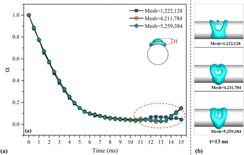
Figure 3. (a) The computational mesh; (b) Schematic drawing of the numerical model and the boundary conditions.
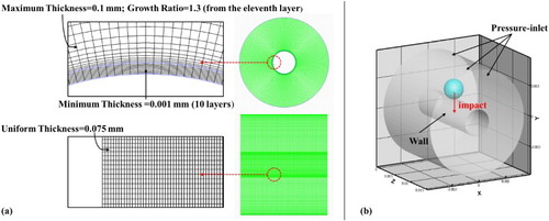
Table 1. The number of cells in the grid independence test.
Figure (b) presents a schematic drawing of the three-dimensional numerical model and boundary conditions. The whole numerical model can be simplified as a spherical water droplet impacting on a smooth cylindrical tube. All boundaries except the substrate were set to the pressure-inlet conditions, and the substrate was set to the wall condition with static contact angles.
The numerical model incorporates the following conditions:
The spherical water droplet is patched before impacting without considering the effect of the air shear force.
Standard atmospheric pressure is adopted.
The heat transfer and the friction of the substrates are not considered.
Incompressible laminar fluid is adopted.
2.3. Experimental verification of the numerical model
An experiment was carried out to verify the feasibility of the numerical model. A high-speed camera (Olympus i-SPEED TR) with a 90-mm Tamron macro lens was used to capture the dynamic images, and the impacting process was recorded at 2000 frames per second. An LED area light was used to provide the backlight for capturing the images. The impacting water droplet was generated from a stainless-steel needle, and the water in the syringe was pushed using a syringe pump. A schematic drawing of the experimental setup is shown in Figure . The cylinder was made of copper, and the substrate surface was treated with a chemical etching method (Yu, Citation2013) in order to form a low-surface energy substrate. The average static contact angle of the experimental substrate was 148°. In summary, the whole process comprised a pure water droplet impacting on a hydrophobic cylindrical substrate. The operating conditions of the experiment are presented in Table .
Figure 4. Schematic drawing of the experimental setup.
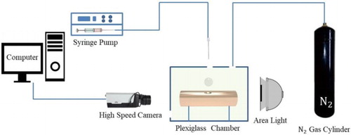
Table 2. The operating conditions of the experiment.
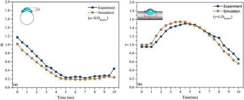
The dimensionless parameters and
and the relative size of the droplet to the substrate
are defined as
(6)
(7)
(8) where H is the thickness of the liquid film on the top of the cylinder, L is the length of the spreading liquid film along the axial direction of cylinder,
is the initial diameter of the impacting droplet and
is the diameter of the cylindrical substrate.
A comparison of the experimental and simulated results over the 10-ms impacting process shows that the morphological behaviors coincide well (Figure ). In addition to the morphological comparison, the quantitative results of the numerical simulation and the experiment were also compared (Figure ), further demonstrating that both sets of results exhibit the same changing trends over time, and coincide acceptably. Therefore, these morphological and quantitative comparisons prove the proposed numerical model feasible.
Figure 5. Morphological comparison of the experimental and simulated results of the droplet impacting on the cylinder: (a) front view; (b) side view.
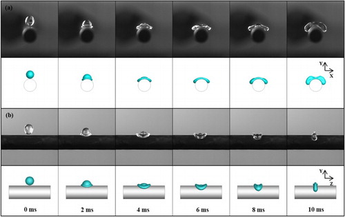
Figure 6. Quantitative comparison of the experimental and simulated results of the droplet impacting on the cylinder. (a) ; (b)
.
3. Results and discussion
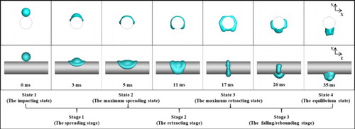
When selecting impact velocities, this study focuses on two main typical impacting modes: capturing mode, which refers to the portion of the impacting droplet that is totally captured by the cylinder, and falling mode, which refers to the some or all portions of the impacting droplet that fall from the cylinder. Mao, Kuhn, and Tran (Citation1997) define four typical distinct states that occur when the impacting process takes place on a flat substrate. Although this study deals with a cylindrical substrate, it is still likely that there are four typical states, but their meanings are much different. These four states and their definitions are as follows: the impacting state is the moment at which the droplet makes contact with the substrate; the maximum spreading state is the moment at which the droplet spreads to its maximum spreading length on the top of the cylindrical substrate along the axial direction; the maximum retracting state is the moment at which the droplet retracts to the minimum retracting length on the top of the cylindrical substrate along the axial direction; and the equilibrium state is the moment at which the three-phase contact line of the residual liquid on the substrate has no obvious movement. These four states separate the whole dynamic impacting process into three stages: the spreading stage, the retracting stage and the falling/rebounding stage.
3.1. The dynamic impacting process
Figure shows the full sequence of a 3.3-mm droplet impacting on a 4.4-mm cylinder (θ = 67°) at an initial impact velocity of 0.7 m/s. The impacting state – i.e., the moment at which the droplet makes contact with the substrate at t = 0 ms, after which the droplet starts spreading by the effect of inertia. Unlike the impacting phenomenon on a flat substrate, the way in which the liquid spreads along the axial direction is obviously different from the way in which it spreads along the circumferential direction, as the latter is affected by the shape of the cylindrical curved surface and the circumferential component of gravity. At t = 5 ms the maximum spreading state occurs, but – unlike in the case of impact on a flat substrate – the impacting droplet does not reach the maximum contact area at this moment. During the retracting stage, the droplet retracts on the top of the cylinder along the axial direction but still continues flowing on the cylinder along the circumferential direction due to the effect of the circumferential component of gravity, and there is a moment at which the droplet reaches the maximum contact area. At t = 17 ms the maximum retracting state occurs, at which point the droplet retracts to the minimum length on the top of cylinder along the axial direction. During the falling/rebounding stage, two kinds of flowing patterns can occur: if the droplet possesses enough energy, it jumps and rebounds from the substrate; however, if it does not possess enough energy to rebound, it flows along the circumferential direction of the cylinder by the effect of gravity and is cut into two or three main parts by the cylinder. The equilibrium state is achieved at t = 35 ms, at which point there is not enough residual energy to drive the droplet’s movement and the three-phase contact line of residual liquid on the substrates exhibits no obvious movement.
Figure 7. The dynamic process of a 3.3-mm droplet impacting on a 4.4-mm cylinder (θ = 67°) at an initial impact velocity of 0.7 m/s.
3.2. The effect of the surface wettability
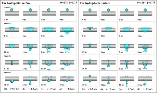
Impacts at velocities of 0.7 and 1.7 m/s on 67°, 90°, 105° and 135° substrates were examined for the purpose of studying the effect of the surface wettability on the droplet impact dynamics. Figure shows the dynamic sequences at the two impact velocities for different surface wettability substrates. During the spreading stage, the sequences are similar in all cases because the inertia dominates the spreading process. The droplet with the higher impact velocity possesses higher inertia, which makes the liquid film spread more extensively along the axial and circumferential directions. Furthermore, the spreading length along the axial and circumferential directions decreases as the contact angle of the substrate increases. During the retracting stage, huge differences can be seen. At the lower impact velocity of 0.7 m/s, the retraction deformations are similar, and the liquid films retract together along the axial direction to finally form a liquid hoop on the substrate. However, at the higher impact velocity of 1.7 m/s, Figure (e) shows that the liquid film on the 67° substrate breaks up to form many small holes at the slimmest parts and exhibits almost no obvious retraction. As the surface contact angle increases, the ability of the liquid film to break apart decreases and the retraction length along the axial direction increases. During the falling/rebounding stage, at the lower impact velocity of 0.7 m/s for the lower contact angles – Figures (a) to (c) – the liquid still attaches to the substrate and the liquid films are pulled to the bottom by the circumferential component of gravity. However, in Figure (d) the liquid rebounds off the 135° substrate and splashes into pieces. At the higher impact velocity of 1.7 m/s, the rebounding and splashing ability of the liquid film increases as the contact angle of the substrate increases. In the equilibrium state, at the lower impact velocity of 0.7 m/s a significant amount of residual liquid attaches to the bottom of the substrate in Figure (a), whereas the residual liquid in Figures (b) and (c) is separated into three parts by the substrate, and almost no residual liquid can be seen on the substrate in Figure (d). At the higher impact velocity of 1.7 m/s, small scattered droplets distribute on the 67° substrate in Figure (e), whereas in Figures (f) to (h) the satellite droplets rebound off the cylindrical substrates, and only a small amount of residual liquid is distributed on the top of cylinder.
Figure 8. Dynamic impacting sequences (β = 0.75) with an impact velocity of 0.7 m/s on a cylindrical surface with contact angles of: (a) 67°; (b) 90°; (c) 105°; (d) 135°; and dynamic impacting sequences (β = 0.75) with an impact velocity of 1.7 m/s on a cylindrical surface with contact angles of: (e) 67°; (f) 90°; (g) 105°; (h) 135°.

Figures (a) and (b) show the difference in the liquid–substrate contact areas for the two impact velocities. The liquid–substrate contact area curves for the lower impact velocity of 0.7 m/s exhibit obvious fluctuations that result from the impacting droplet demonstrating clear spreading and retracting behavior on the substrate (Figure (a)). Conversely, the liquid–substrate contact area curves for the higher impact velocity of 1.7 m/s do not exhibit re-raising behavior because the retracting phenomenon of the impacting droplet is inadequate at this higher velocity (Figure (b)). In the maximum contact area state and the equilibrium state, the liquid–substrate contact area decreases as the contact angle of the substrate increases. In the falling mode, the liquid–substrate contact areas in the cases with a hydrophobic substrate are obviously smaller than those in the cases with a hydrophilic substrate in the equilibrium state.
Figure 9. (a) The liquid–substrate contact areas at an impact velocity of 0.7 m/s for different contact angles; (b) the liquid–substrate contact areas at an impact velocity of 1.7 m/s for different contact angles; (c) the volume of residual liquid captured by the cylinder in the equilibrium state.
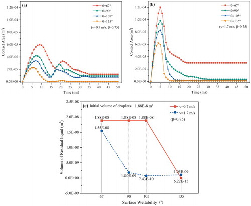
Figure (c) shows the volume of residual liquid that remains on the substrates at the equilibrium stage. In the capturing mode, the entire impacting droplet is captured by the cylinder, and the residual liquid on the cylindrical substrate is equal to the volume of the initial impacting droplet. In the falling mode, the residual liquid on the cylinder decreases as the contact angle of the substrate increases, and the hydrophobic cylinder leads to a great reduction in the volume of residual liquid that remains on the cylinder.
3.3. The effect of the impact velocity
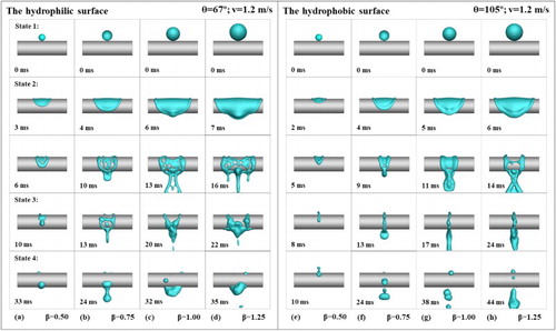
Impacts at velocities of 0.7, 1.2, 1.7 and 2.2 m/s on substrates with contact angles of 67° and 105° were examined for the purpose of studying the effect of the impact velocity on the droplet impact dynamics. Figure shows the dynamic sequences of droplets impacting on hydrophilic and hydrophobic substrates at different velocities. During the spreading stage, a higher impact velocity creates higher inertia, which causes the liquid film to spread more completely. In particular, when reaching the maximum spreading state, the droplet in Figure (d) spreads so widely that the liquid film merges together at the bottom of the cylinder. Comparing Figure (d) with (h), although the droplet has the same initial kinetic energy it spreads over a smaller area, indicating that substrates with lower wettability can inhibit the spread of impacting droplets. During the retracting stage, huge differences can be seen between all eight cases. On the hydrophilic substrate, higher impact velocities result in a fiercer disturbance, which can cause the liquid film to break up more completely; at higher velocities it is more likely that holes will form across the entire area where the liquid film is thin enough, and that small droplets will be scattered across the substrate. On the hydrophobic substrate, the retracting ability of the liquid film decreases as the impact velocity increases; at higher velocities, the droplet is disturbed more fiercely and can form more scattered droplets. The phenomenon in Figure (h) is of particular interest, as the high impact velocity leads to the liquid film completely breaking up. The impact dynamics of Figures (d) and (h) appear to be similar; however, the volume of residual liquid on the hydrophilic cylindrical substrate is about 3.4 times that on the hydrophobic cylindrical substrate. In the equilibrium state, the visible residual liquid on the hydrophilic cylinder is obviously greater than that on the hydrophobic cylinder for the corresponding impact velocity. Furthermore, as the impact velocity increases, the impacting droplet become more susceptible to breaking up into small scattered droplets. In the falling mode, the residual liquid disperses around the hydrophilic cylinder; however, the residual liquid is mainly distributed on the top of the hydrophobic cylinder.
Figure 10. Dynamic impacting sequences (β = 0.75) for impacts on a hydrophilic cylindrical surface (θ = 67°) at impact velocities of: (a) 0.7 m/s; (b) 1.2 m/s; (c) 1.7 m/s; (d) 2.2 m/s; and dynamic impacting sequences (β = 0.75) for impacts on a hydrophobic cylindrical surface (θ = 105°) at impact velocities of: (e) 0.7 m/s; (f) 1.2 m/s; (g) 1.7 m/s; (h) 2.2 m/s.
Figures (a) and (b) show the liquid–substrate contact area for the two types of cylindrical substrates. It can be seen that as the impact velocity increases, the time it takes to reach the maximum contact area state becomes shorter and the liquid–substrate contact area increases in the maximum contact area state. The higher impact velocities provide the impacting droplet with greater amounts of kinetic energy, which drive the droplet to spread more easily and lead to a wider contact area. In the equilibrium state, the liquid–substrate contact area of the hydrophilic cylinder increases as the impact velocity increases, because higher impact velocities lead to more scattered droplets, and these small scattered droplets which distribute on the substrate lead to an increase in the total liquid–substrate contact area.
Figure 11. (a) The liquid–substrate contact areas on a hydrophilic cylinder (θ = 67°) at different impact velocities; (b) the liquid–substrate contact areas on a hydrophobic cylinder (θ = 105°) at different impact velocities; (c) the volume of residual liquid captured by the cylinders in the equilibrium state.
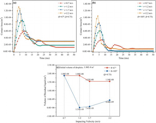
Figure (c) shows the volume of residual liquid that remains on the substrates in the equilibrium stage. On the hydrophilic cylinder, the volume of residual liquid decreases as the impact velocity increases, because greater amounts of kinetic energy cause more liquid to fall off the substrate. However, on the hydrophobic cylinder, as the impact velocity increases, the volume of residual liquid on the substrate first decreases and then begins to increase. It is posited that there is an optimal impact velocity which can lead to the minimum volume of residual liquid on the cylinder; knowing this velocity would be very helpful when designing heat exchanger structures in order to improve the heat transfer efficiency of the hydrophobic heat transfer pipes. This will be investigated in depth in future work.
3.4. The effect of the droplet–substrate size ratio
Impacts of different sized droplets on hydrophilic and hydrophobic substrates were examined for the purpose of studying the effect of the droplet–substrate size ratio on the droplet impact dynamics. Figure shows the dynamic sequences of different sized droplets on hydrophilic and hydrophobic substrates. It can be seen that as the droplet size increases, the spreading area of the liquid film becomes larger. The retracting phenomena on the hydrophobic cylinder are obvious; even the droplet of the size β=1.25 retracts together and becomes a liquid hoop. In contrast, as the droplet size increases, the retracting ability of the liquid film decreases for the hydrophilic cylinder. In the equilibrium state, on the hydrophilic cylinder the bigger droplets more easily form larger volumes of residual liquid which mainly attach to the bottom of the cylinder. On the hydrophobic cylinder, most portion of liquid is repelled by the substrate, and a small volume of residual liquid attaches primarily on the top of the cylinder.
Figure 12. Dynamic impacting sequences for impacts on a hydrophilic cylindrical surface (θ = 67°) at an impact velocity of 1.2 m/s for: (a) β = 0.50; (b) β = 0.75; (c) β = 1.00; (d) β = 1.25; and dynamic impacting sequences for impacts on a hydrophobic cylindrical surface (θ = 105°) at an impact velocity of 1.2 m/s for: (e) β = 0.50; (f) β = 0.75; (g) β = 1.00; (h) β = 1.25.
Figures (a) and (b) show the liquid–substrate contact area for the two types of cylindrical substrate. As the droplet–substrate size ratio increases, the time it takes to reach the maximum contact area state increases, and the size of the maximum contact area also increases. In the equilibrium state, on the hydrophilic cylinder the contact area increases as the droplet–substrate size ratio increases; however, the increase of the contact area on the hydrophobic cylinder is not obvious, suggesting that the hydrophobic cylinder is good at repelling impacting droplets when designing heat exchangers.
Figure 13. (a) The liquid–substrate contact areas on a hydrophilic cylinder (θ = 67°) at an impact velocity of 1.2 m/s for different values of β; (b) the liquid–substrate contact areas on a hydrophobic cylinder (θ = 105°) at an impact velocity of 1.2 m/s for different values of β; (c) the volume of residual liquid captured by the cylinders in the equilibrium state.
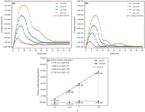
Figure (c) shows the volume of residual liquid that remains on the substrates at the equilibrium stage. As the droplet–substrate size ratio increases, the volume of residual liquid on both types of cylinder also increases. However, the volume of residual liquid is much larger on the hydrophilic cylinder than on the hydrophobic cylinder for the same corresponding conditions – even the volume of residual liquid for droplets of the size β=0.5 on the hydrophilic cylinder is 2.86 times than that of droplets of the size β=1.25 on the hydrophobic cylinder.
4. Conclusions
This paper has examined the impact dynamics of water droplets on cylindrical heat transfer pipes. The effects of three main parameters were explored: surface wettability, impact velocity and droplet–substrate size ratio. The surface wettability was found to have a great effect on the attaching ability of the residual liquid post-impact. As the hydrophobicity of the substrate increases, the volume of residual liquid that remains on the substrate is greatly reduced. Pipes with a hydrophobic substrate can effectively repel impacting droplets, even when the droplet is big or its velocity is low. An appropriate impact velocity can effectively reduce the volume of residual liquid that remains on the pipe. For pipes with varying surface wettability substrates, the droplet size has different effects on the volume of residual liquid: on the hydrophilic substrate as the droplet size increases, the volume of residual liquid also increases, whereas on the hydrophobic substrate as the droplet size increases, a change in the volume of residual liquid is not obvious. The phenomenon of droplets impacting on cylindrical pipes is a complex process, and in order to better understand it the effects of multiple parameters need to be considered together.
Future work will consider using the dynamic contact angle in the model to improve the accuracy of the droplet spreading and retracting dynamics on the substrates. It will also consider the heat transfer between droplets with heat transfer pipes, which will facilitate the addition of energy equations into the existing model.
Disclosure statement
No potential conflict of interest was reported by the authors.
Additional information
Funding
References
- Abolghasemibizaki, M., McMasters, R. L., & Mohammadi, R. (2018). Towards the shortest possible contact time: Droplet impact on cylindrical superhydrophobic surfaces structured with macro-scale features. Journal of Colloid and Interface Science, 521, 17–23. doi: 10.1016/j.jcis.2018.03.005
- Andrew, M., Liu, Y., & Yeomans, J. M. (2017). Variation of the contact time of droplets bouncing on cylindrical ridges with ridge size. Langmuir, 33(30), 7583–7587. doi: 10.1021/acs.langmuir.7b01625
- Comtet, J., Keshavarz, B., & Bush, J. W. M. (2016). Drop impact and capture on a thin flexible fiber. Soft Matter, 12(1), 149–156. doi: 10.1039/C5SM02037A
- Dressaire, E., Sauret, A., Boulogne, F., & Stone, H. A. (2016). Drop impact on a flexible fiber. Soft Matter, 12(1), 200–208. doi: 10.1039/C5SM02246K
- Faizollahzadeh Ardabili, S., Najafi, B., Shamshirband, S., Minaei Bidgoli, B., Deo, R. C., & Chau, K.-W. (2018). Computational intelligence approach for modeling hydrogen production: A review. Engineering Applications of Computational Fluid Mechanics, 12(1), 438–458. doi: 10.1080/19942060.2018.1452296
- Hung, L. S., & Yao, S. C. (1999). Experimental investigation of the impaction of water droplets on cylindrical objects. International Journal of Multiphase Flow, 25(8), 1545–1559. doi: 10.1016/S0301-9322(98)00085-8
- Kim, S.-G., & Kim, W. (2016). Drop impact on a fiber. Physics of Fluids, 28(4), 261–266. doi: 10.1063/1.4945103
- Liang, G., Guo, Y., Yang, Y., Guo, S., & Shen, S. (2013). Special phenomena from a single liquid drop impact on wetted cylindrical surfaces. Experimental Thermal and Fluid Science, 51, 18–27. doi: 10.1016/j.expthermflusci.2013.06.012
- Liang, G., Guo, Y., Yang, Y., & Shen, S. (2014). Liquid sheet behaviors during a drop impact on wetted cylindrical surfaces. International Communications in Heat and Mass Transfer, 54, 67–74. doi: 10.1016/j.icheatmasstransfer.2014.03.010
- Liang, G., Mu, X., Guo, Y., & Shen, S. (2016). Crown and drop rebound on thin curved liquid films. International Journal of Heat and Mass Transfer, 98, 455–461. doi: 10.1016/j.ijheatmasstransfer.2016.03.046
- Liang, G., Yang, Y., Guo, Y., Zhen, N., & Shen, S. (2014). Rebound and spreading during a drop impact on wetted cylinders. Experimental Thermal and Fluid Science, 52, 97–103. doi: 10.1016/j.expthermflusci.2013.09.001
- Liu, Y., Andrew, M., Li, J., Yeomans, J. M., & Wang, Z. (2015). Symmetry breaking in drop bouncing on curved surfaces. Nature Communications, 6, 10034. doi: 10.1038/ncomms10034
- Lorenceau, É., Clanet, C., & Quéré, D. (2004). Capturing drops with a thin fiber. Journal of Colloid and Interface Science, 279(1), 192–197. doi: 10.1016/j.jcis.2004.06.054
- Lorenceau, E., Clanet, C., Quéré, D., & Vignes-Adler, M. (2009). Off-centre impact on a horizontal fibre. The European Physical Journal Special Topics, 166(1), 3–6. doi: 10.1140/epjst/e2009-00868-0
- Mao, T., Kuhn, D. C. S., & Tran, H. (1997). Spread and rebound of liquid droplets upon impact on flat surfaces. AIChE Journal, 43(9), 2169–2179. doi: 10.1002/aic.690430903
- Mou, B., He, B.-J., Zhao, D.-X., & Chau, K.-W. (2017). Numerical simulation of the effects of building dimensional variation on wind pressure distribution. Engineering Applications of Computational Fluid Mechanics, 11(1), 293–309. doi: 10.1080/19942060.2017.1281845
- Nichols, B. D., Hirt, C. W., & Hotchkiss, R. S. (1981). A fractional volume of fluid method for free boundary dynamics. In Seventh international conference on numerical methods in fluid dynamics (pp. 304–309). Springer, Berlin, Heidelberg.
- Osher, S., & Sethian, J. A. (1988). Fronts propagating with curvature-dependent speed: Algorithms based on Hamilton–Jacobi formulations. Journal of Computational Physics, 79(1), 12–49. doi: 10.1016/0021-9991(88)90002-2
- Pasandideh-Fard, M., Bussmann, M., Chandra, S., & Mostaghimi, J. (2001). Simulating droplet impact on a substrate of arbitrary shape. Atomization and Sprays, 11(4), 397–414. doi: 10.1615/AtomizSpr.v11.i4.60
- Sussman, M., & Puckett, E. G. (2000). A coupled level set and volume-of-fluid method for computing 3D and axisymmetric incompressible two-phase flows. Journal of Computational Physics, 162(2), 301–337. doi: 10.1006/jcph.2000.6537
- Vadloori, B., Sharath, A. K., Prabhu, N. P., & Maurya, R. (2018). Homology modelling, molecular docking, and molecular dynamics simulations reveal the inhibition of Leishmania donovani dihydrofolate reductase-thymidylate synthase enzyme by Withaferin-A. BMC Research Notes, 11(1), 246–252. doi: 10.1186/s13104-018-3354-1
- Yu, D. (2013). Preparation and estimation of wear and corrosion resistance superhydrophobic surfaces by electrodeposition (Doctoral dissertation). Retrieved from http://www.cnki.com.cn
- Zhu, Y., Liu, H. R., Mu, K., Gao, P., Ding, H., & Lu, X. Y. (2017). Dynamics of drop impact onto a solid sphere: Spreading and retraction. Journal of Fluid Mechanics, 824, R3-1–R3-11. doi: 10.1017/jfm.2017.388