
 ?Mathematical formulae have been encoded as MathML and are displayed in this HTML version using MathJax in order to improve their display. Uncheck the box to turn MathJax off. This feature requires Javascript. Click on a formula to zoom.
Abstract
For a combustion-based thermophotovoltaic generator (TPV), the baffle-induced reacting flows are numerically investigated in the micro combustor with a multihole baffle representing a mixed feature of bluff body and multiple jets. The lobed flow feature is realized by the momentum difference between fuel and air streams and the baffle wall, not the geometrical conditions like a lobed nozzle. Compared with the H2–air combustor, the lobed flame and the votical structure are enhanced for the CH4–air combustor. To analyze the lobed structure, the lobe intensity and the equivalent perimeter are defined for the stoichiometric mixture line. The maximum lobe intensity is observed at the beginning zone of flame, whereas the equivalent perimeter is increased near the active reaction zone. As the baffle thickness decreases, the lobe structure is enhanced due to the increased vortices. Also, a close relationship between the maximum vorticities at the baffle exit and the maximized lobe structure is observed. The intensified lobe structure contributes to a shorter flame length and more efficient combustion, resulting in increased radiation available for a micro-TPV system. When the lobe structure is enhanced, the high emitter efficiency for an energy conversion device is obtained as 0.319–0.326 for the H2–air combustor.
Nomenclature
| a | = | Radius to crest of lobed Z = Zst line, m |
| b | = | Radius to trough of lobed Z = Zst line, m |
| CRZ | = | Center recirculation zone |
| Ilob | = | Lobe intensity, a/b |
| LHV | = | Lower heating value, MJ/kg |
| Lf | = | Flame length, m |
| Peq | = | Equivalent perimeter, m |
| T | = | Temperature, K |
| Tavg | = | Area-averaged wall temperature, K |
| Tw | = | Outer wall temperature, K |
| T∞ | = | Ambient temperature, K |
| U | = | Streamwise velocity, m/s |
| Uc | = | Streamwise velocity at fuel hole center of baffle exit, m/s |
| Ui | = | Velocity component in i-direction, m/s |
| WRZ | = | Wall recirculation zone |
| Xlob | = | Axial position of maximum lobe intensity, m |
| Yi | = | Mass fraction of species i |
| Z | = | Mixture fraction |
| Zst | = | Stoichiometric mixture fraction |
Greek letters
| η | = | Combustion efficiency |
| ηe | = | Emitter efficiency |
| ν | = | Stoichiometric mass ratio |
1. Introduction
Recently, with the increasing demand of micro or small devices, various applications of micro combustors are being explored. The combustion-based micropower systems (milliwatts to watts) have been proposed in various forms, including micro-gas turbine, micro-rotary engines, micro-thermophotovoltaic (TPV) and micro-thermoeclectric generators (TEG). In the systems of micro-gas turbine (Waitz et al., Citation1998) and micro-rotary engine (Fernandez-pello, Citation2002), the power is generated directly by using the heat and kinetic energy of combustion gas. Whereas TPV and TEG systems do not use the kinetic energy of combustion gas and convert the combustion heat into the electrical energy through the wall heat transfer. Also, the combined system of micro-gas turbine and TPV or TEG devices is possible because of being the difference of the power generation form (Kim & Park, Citation2022). In these systems, the role or design of micro combustor can be changed depending on the form of the micropower system, but the efficient micro combustors are commonly required to improve the system performance whether the system is the form of an engine or the form of a combined system. It is because the micro combustor in micropower systems is a core component to convert the chemical energy of fluids into heat energy (Chou et al., Citation2011). However, the micro combustor faces difficulties owing to the reduced space for the mixing of fuel and oxidizer, increased heat loss, insufficient residence time, weakened turbulent fluctuation, and inefficient combustion. In general, these problems can be resolved by creating recirculation flows in the combustion chamber. The recirculating flows improve the mixing and the residence time of fuel and oxidizer. It is possible to develop these features inside the combustor by changing the combustion chamber based on bluff bodies (Bagheri et al., Citation2014; Fan et al., Citation2013; Zhang et al., Citation2015), cavities (Wan et al., Citation2015), baffle plates (Choi et al., Citation2008; Choi & Park, Citation2009; Kim & Park, Citation2018, Citation2019), and backward-facing steps (Akhtar et al., Citation2019). The main idea of these studies is to change the main streams using the secondary flows depending on the combustor shape.
Among them, the baffle plate with multiple holes has a mixed feature of bluff body and multiple jets, because the baffle wall wake is considered as the flow near a bluff body and the flow past the baffle hole is regarded as a jet. Therefore, if the flow passes through the baffle plate, three-dimensional recirculations can naturally occur due to the streamwise momentum difference between jet flows and the baffle wall. According to Kim and Park (Citation2018, Citation2019), two large vortical regions called wall and center recirculation are formed by the interaction between center jet and annularly placed jets for multihole baffled micro combustors. And, the lobed flow structure of the streamwise velocity is commonly observed. In the case of the combustor having a high combustion efficiency, such lobed flow becomes more and more clear. This feature of the micro combustor with the baffle plate can be useful to control various potential possibilities for an energy conversion device. Accordingly, the generation of recirculating zones and the development of the lobed flow can be an important feature of the baffled micro combustor, but generation conditions and secondary flow characteristics related to the lobed flow structure have not been closely studied in a micro combustor.
From a literature survey, the lobed flow structure is dominated by the secondary flows due to the lobed shape like lobed mixer and lobed nozzle. It has been widely used to get efficient combustion, reduced pollutants, and reduced jet noise. Early studies are concentrated on lobed types comprised of corrugated surfaces like sinusoidal and scalloping shapes to understand the geometrical feature for mixing enhancement. Smith et al. (Citation1997) conducted the experimental studies of the non-reactive mixing processes in a lobed fuel injector, which consists of two corrugated plates. The lobed injector showed a 30% increase in mixing performance compared to a non-lobed injector. Hu et al. (Citation2000, Citation2001, Citation2002) studied exhaust ejector/mixer systems based on lobed nozzles with rectangular mixing tubes. The lobed nozzles enhance the mixing process between the high-temperature and high-speed gas plume and ambient cold air. Such lobed nozzles generate large-scale streamwise vortices and highly strained flowfields for enhanced mixing. Also, Cai et al. (Citation2010) studied the generation and evolution of vortical flows in the jets from notched circular nozzles. The notched nozzle jets show the mixing enhancement due to the development of secondary flows. Their study found that the variation of streamwise vortices and secondary flows is similar to the lobed flow structure. Based on these studies, we deduce that the distorted azimuthal vortices in a jet flow induce additional streamwise vortices. Many methods can generate additional vortices to the mainstream. In the case of the baffled micro combustor, it is interesting that the lobed flow structure can be implemented by the momentum difference of fuel and air jets through the baffle plate.
When the lobed flow develops, the secondary motions are strengthened than the non-lobed flow. The central fluid moves outward by such secondary flows, and then the ambient fluid flows into the central region. Streamwise vortices are also generated as a result of these features, and mixing is improved. In the baffled micro combustor, the special characteristics of the lobed flow are mainly attributed to the baffle hole configuration, whereas the general lobed flow is dominated by the noncircularity degree of corrugated surfaces. However, the relationship between the hole condition and the generation of the lobed flow has received little attention. The related results may provide useful information for expanding the production method of the lobed flow structure using a flat plate with multiple holes. Furthermore, many studies on lobed flow have concentrated on the flow mixing of hot and cold fluids, but few studies have focused on reacting flow coupled to lobed flow. Since the combustion reaction is the important phenomenon of various applications, understanding reacting flows based on the lobed flow structure would be very meaningful to get an efficient combustor.
In the present study, the influence of the lobed flow structure on turbulent combustion characteristics is investigated when the baffle plate with multiple holes is introduced in a micro combustor. The previous study (Kim & Park, Citation2018) shows that large recirculation regions are mainly changed by the baffle hole conditions of diameter, shape, and position. As a result, the lobed flow structure can be differently obtained according to the feature of baffle configuration. Meanwhile, the typical flow structure in the lobed jet flows is determined by the inflow conditions such as number, surface shape, and penetration angle of lobes (Paul et al., Citation2020; Sheng et al., Citation2015). Based on these findings, the geometrical condition of the baffle plate has a great influence on the axial flow patterns because the baffle exit can be considered as the inlet of the combustion chamber. Therefore, the inflow condition of the baffled micro combustor is controlled by changing baffle shapes. The main shape variable is chosen to be the baffle thickness. Changing the baffle thickness results in a variety of jet flows past the baffle hole. The jet flow has orifice characteristics for the thin baffle and fully developed pipe characteristics for the thick baffle. As a result, it is worthwhile to investigate the effect of baffle thickness on reaction flows. For combustion with air, the common fuels hydrogen and methane are chosen. In lobed jets, the lobe structure significantly affects the flow and thermal field because of adding streamwise vortices. Therefore, it is necessary to examine the coupling of the lobed flow structure and two large vortical regions of wall and center recirculation. From the results, the variables related to the lobed flow structure are discussed for different fuels. The lobe structure of the stoichiometric mixture line is investigated for reacting flows to explain combustion characteristics for different baffle thicknesses. The lobe intensity and the equivalent perimeter of such lobed stoichiometric line are introduced. Various parameters of the flame length, combustion efficiency, and wall heat flux are discussed with the axial variations of the lobe intensity.
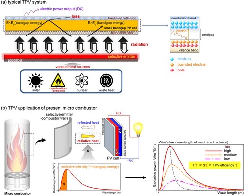
Based on such lobed flames, the present micro combustor is combined with micro-TPV as shown in Figure . A typical TPV system consists of three parts: a heat source, an emitter, and a photovoltaic cell with the low bandgap energy (0.4–0.7 eV). When various types of heat energy such as solar heat, combustion heat, nuclear heat, waste heat etc. are provided, the radiant heat is emitted from the emitter. The bounded electron in the PV cell is excited by higher thermal radiation than the bandgap energy. Figure (b) shows the combination of present micro combustor and micro-TPV. According to Wien’s law, as the radiation heat increases, the bandgap energy is reduced. Therefore, as the emitter temperature increases, the performance of the TPV system can be improved. When a combustor is adopted as the heat source, the emitter temperature is closely related to the combustion efficiency. The present combustor can get various heat transfer rates depending on changes of the lobed flame structure. Based on such flame and heat transfer characteristics, the feature for an energy conversion device is explored.
Figure 1. Schematic of the present micro combustor combined with micro-thermophotovoltaic.
2. Numerical procedure
2.1. Governing equations
When the Reynolds number in the micro combustor with a bluff body is greater than 500, a proper turbulence model is required to predict flow mixing and combustion characteristics (Kuo & Ronney, Citation2007). As previously shown in the study (Choi et al., Citation2008; Kim & Park, Citation2018, Citation2019), the multihole baffled micro combustor has the interaction of multiple jets and various vortical structure near the baffle plate of x < 5D. The increased strain rates become the significant source of turbulent kinetic energy. Therefore, the turbulent simulation is required even if the inflow has laminar flow characteristics. The Reynolds stress model (RSM) is adopted for better prediction of three-dimensional turbulent recirculations. From Kim and Park (Citation2022), the baffled micro combustor has unsteady features and it is dominated by a monotone frequency of three-dimensional vortices. They showed that the steady field is almost similar to the time-averaged field. Therefore, the study on various shapes of micro combustor is based on the time-averaged field, because the investigation of dynamic vortices is not purpose. For steady-state and incompressible turbulent reacting flows, the governing equations of the continuity, momentum, mass fraction of species i, enthalpy, and Reynolds stress are as follows
(1)
(1)
(2)
(2)
(3)
(3)
(4)
(4)
(5)
(5) where
,
,
,
,
, Yi, Di,m,
,
,
, Dij, Pij, ϕij, and εij are density, velocity, Reynolds stress, stress tensor, pressure, mass fraction of species i, diffusion coefficient, chemical reaction source, enthalpy, temperature, diffusion of Reynolds stress, production of Reynolds stress, pressure–strain correlation, and anisotropic dissipation rate, respectively. The anisotropic dissipation rate is obtained by εij = 2ρεδij/3, where δij is the kronecker delta. The turbulent viscosity μt is calculated as μt = ρCμk2/ε (Cμ = 0.09), where the dissipation rate of turbulent kinetic energy (ε) is computed from the transport equation. The turbulent Schmidt and Prandtl numbers are Sct = 0.7 and Prt = 0.85, respectively. For simplicity, details of turbulence model functions and constants are omitted. To examine the flame characteristics preferentially, the radiating heat from the combustion gases in the flame to the combustor wall is neglected (Kim & Park, Citation2018; Zhang et al., Citation2015). The governing equations are solved by ANSYS 13.0 (Citation2006). The SIMPLEC algorithm for the pressure-velocity coupling and the second-order upwind scheme for the convection terms are adopted. The convergence criterion is set as
.
2.2. Computation domain and boundary conditions
The computational domain of the micro combustor with a multihole baffle plate is depicted in Figure . The baffle has a fuel hole in the center and annular six air holes around it. According to Mi and Nathan (Citation2010) and Kim and Park (Citation2020, Citation2021), the inflow types of a smooth nozzle, a sharp-edged orifice, and a long pipe significantly affect jet development and axis-switching flow. Each inlet has its own set of secondary flow components, and these secondary flows at the inlet dominate the development of the jet flow. In this study, the flows past the baffle plate are considered as the inflow of the combustion chamber. The nature of such inflow can be changed by the baffle thickness (bt). The fuel and air jets passing through the thin baffle have orifice inflow characteristics, whereas the thick baffle jets have long pipe inflow characteristics. Based on this, the variation of the baffle thickness is tried to get different fuel and air jets. The bt change induces different typical vortices because the inlet of the micro combustor is differently assigned by such change. Also, the lobed flow structure is related to the secondary flow development in the combustor cross-section. Accordingly, we comprehend that the bt change is meaningful to see the lobed structure and its effect on the flame structure. In terms of baffle design, various parameters such as the hole diameter, the number of air holes, their position, etc., should be considered for efficient combustion. However, for reacting flows, it is difficult to distinguish the characteristics of one variable while considering many variables at the same time. Therefore, a baffle configuration of seven holes is selected based on the previous studies of Kim and Park (Citation2018, Citation2019). In the preliminary process, the combustor length is changed for L = 50Df, 100Df 150Df, and 200Df. As a result, the length is determined to be more than the maximum flame length. The geometrical condition is summarized in Table . The baffle thickness is changed for bt/Df = 0.01, 0.05, 0.1, 0.3, 0.5, 0.75, and 1.5.
Figure 2. Computational domain and different baffle plates.
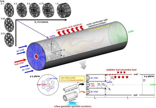
Table 1. Geometric conditions.
The constant mass flow rate is applied for the inlet boundary. At the inlet, the mass flow rates of fuel and air are an important factor in determining the flame pattern. The global equivalence ratio based on the inlet mass flow rate is set to 1. It is calculated by ϕG = AFst/AF where AFst denotes the stoichiometric air–fuel mass flow ratio and AF is the inlet air–fuel mass flow ratio . Then, the inlet Reynolds number based on the combustor diameter (D = 2.8 mm) is ReD = ρmUmD/μm = 500, where ρm, Um, and μm are the mean density, streamwise velocity, and dynamic viscosity considering the inflow of fuel and air. For ϕG = 1, AFst = AF =
. Here, ρ, A, and U are density, cross-sectional area, and streamwise velocity at the inlet, respectively. The air velocity is expressed by
. The mixture density satisfies the relation of
based on the fluid masses. After replacing the fluid mass with the mass flow rate, the mean density
is calculated by using AFst = 17.11 for the CH4–air combustion and AFst = 34.11 for the H2–air combustion. The mean viscosity μm is similarly calculated. First, Um is obtained by ReD = 500. From a combination of
and
, the velocities of air and fuel are determined. In Table , velocities, momentum fluxes, and Reynolds numbers at the inlet are presented. To get the spatial distributions of velocity and turbulence variables, the inflow generator of Kim and Park (Citation2021) is adopted as Figure . The inlet temperatures of fuel and air are 300 K. At the outlet, a constant pressure condition of P = Pout is applied and the others are used by the Neumann boundary condition. For wall boundaries, the enhanced wall treatment for turbulence modeling and zero fluxes of species are adopted (Khalil et al., Citation2019; Sui et al., Citation2021). The reacting flow and heat transfer are analyzed by the conjugate heat transfer including the baffle plate and the combustor wall. The temperature field of the solid zone is calculated by solving
, where λw is the wall thermal conductivity. The balance of heat fluxes at the solid-fluid interface is treated by
, where λfluid is the fluid thermal conductivity. The resulting temperature is commonly assigned at the boundaries of solid and fluid zone. The boundary conditions and the wall property are summarized in Table . To estimate the heat loss from the combustor wall, the combustor wall is treated by the convective and radiative heat transfer. The wall heat flux of the combustor wall is an important factor for the development of an efficient micro combustor. The growing heat loss means a reduction in the stability and efficiency of the combustion chamber. However, to configure energy conversion devices, the increased wall heat transfer is a better condition. Therefore, such conflicting characteristics need to be reviewed for the change of baffle shape.
Table 2. Inlet conditions of ϕG = 1.0.
Table 3. Boundary conditions of multihole baffled micro combustor.
2.3. Combustion model
To get reacting flows, the reaction mechanism is selected as 325 reactions of GRI-Mech 3.0 (Citation1999) for CH4–air combustion and 19 reactions of Giovangigli and Smooke (Citation1987) for H2–air combustion. The turbulent flame structures of non-premixed combustions are investigated by the eddy dissipation concept (EDC). The mixture fraction Z is the local mass ratio of material originating from the fuel stream to the mixture of fuel and air. In general, the flame structure is estimated by the stoichiometric mixture fraction Zst, because the chemically complete combustion is made in the vicinity of the stoichiometric condition of Z = Zst. Based on this feature, the flame length is obtained from the position of the stoichiometric condition Zst along the centerline (Kim & Park, Citation2018). The stoichiometric conditions of hydrogen and methane reactions are obtained by two global reactions
(6)
(6)
(7)
(7) The mixture fraction is locally related to the mass fractions of the fuel and oxygen.
(8)
(8) Here, ν is the stoichiometric mass ratio
. The stoichiometric coefficients are
and
for CH4–air combustion and
,
for H2–air combustion.
denotes the mass fraction of fuel in the inlet fuel flow and
is the mass fraction of oxygen in the inlet oxidizer flow (e.g.
for air). For a stoichiometric mixture, the fuel and oxidizer are completely consumed and
and
are obtained. From this definition, the stoichiometric mixture fraction is calculated by
for CH4–air combustion and
for H2–air combustion. The basic characteristics of CH4–air and H2–air reactions are summarized in Table . The gas density is calculated by the ideal equation of state at 101,325 Pa.
Table 4. Comparison of CH4–air and H2–air combustion.
2.4. Model validation
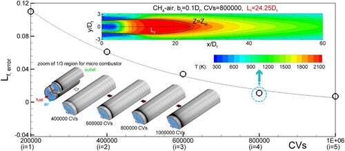
Before proceeding further, the grid dependency is performed for five cases. The number of control volumes (CV) is changed by 200,000 (i = 1), 400,000 (i = 2), 600,000 (i = 3), 800,000 (i = 4), 1,000,000 (i = 5). The near wall modeling of turbulence equations is based on the enhanced wall treatment (Espinoza-Jara et al., Citation2022). To solve the viscous sublayer, the first grid points near the wall are located at y+ ∼ 1, where y+ is the maximum of non-dimensional normal lengths at the first grid from the wall. If y+ ∼ 1 is not satisfied when the converged solution is obtained, the grid spacings are readjusted. The minimum axial spacing is almost maintained at Δx/D = 0.005 and the maximum axial spacing is changed for Δx/D = 0.042 (200,000 CVs), 0.036 (400,000 CVs), 0.028 (600,000 CVs), 0.023 (800,000 CVs), and 0.016 (1,000,000 CVs). In Figure , the relative error of flame length is presented for different grids. Here, the error is defined as . As the grid resolution increases, the relative error is gradually decreased and the flame length approaches to a constant value with a specific flame pattern. For the grid larger than 800,000 CVs, the difference between flame lengths is less than 1%. Therefore, the final grid resolution is maintained at more than 800,000CVs.
Figure 3. Comparison of the flame length error for different CVs.
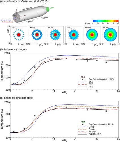
Since there was no data for the flow field of the multihole baffled micro combustor, the flow and temperature fields of jet flame, bluff-body burner, micro cylindrical combustor, micro can combustor were chosen for comparison (Kim & Park, Citation2018, Citation2019, Citation2022). Similarly, to check the adopted turbulence and combustion models, several calculations are performed for the experiment of Veríssimo et al. (Citation2015) because their combustor is similar to the present baffled micro combustor. As shown in Figure (a), the combustor consists of a central air orifice and around 16 methane orifices. The streamwise velocity variation from the multiport inlet is similar to that of the multiple air jets past the baffle plate. The thermal field of a combustor is nonlinearly coupled to the flow and turbulent field. The combination of combustion and turbulent models needs to be examined for the change of the temperature field. In Figure (b), temperature distributions of the standard k-ε model (SKE), the shear stress transport k-ω model (SST), and the RSM model are compared. Here, Da is the diameter of the air orifice. For the RSM model, the turbulent kinetic energy k is defined by . The mixing of fuel and air is enhanced near the injection surface because the fuel and air through the multihole plane are provided to the combustion chamber. The resulting temperature rise is observed for x/Da < 14. The RSM model well predicts it. For the CH4–air combustor, the combustion model is tested by the 2-step EDC (Westbrook & Dryer, Citation1981), the 6-step EDC (Jones & Lindstedt, Citation1988), the 41-step EDC (Yang & Pope, Citation1998), and the detailed mechanism of GRI-Mech 3.0 (Smith et al., Citation1999). As can be seen in Figure (c), the GRI-Mech 3.0 mechanism gives higher accuracy than other mechanisms. Based on these results, it is considered that the combination of RSM and the GRI-Mech 3.0 mechanism can be effectively used to capture the multihole effect on reacting flows in the baffled micro combustor.
Figure 4. Comparison of temperature profiles along center axis between predicted result and experimental data: dependency of (b) turbulence models, and (c) chemical kinetic models.
3. Results and discussion
3.1. Flow characteristics
As explained in Kim and Park (Citation2018, Citation2019), the multihole baffled micro combustor generally has two large recirculation zones derived by the baffle plate. In Figure (a), the recirculation zone characteristics of x–y and x–z planes are explained by velocity vectors, streamlines, and contours of U/Uc. As the fuel and air jets progress downstream, the shear layers grow radially. Such development of jets entrains the ambient fluids. As a result, the wall recirculations like backward-facing flows are generated near the region between fuel and air jets and the combustor wall (see blue lines). In the central region, the fuel flow after the baffle plate shows the general jet flow. When the axial momentum of the fuel jet is weakened, the fuel flow is entrained by the air flow. As a result, the center recirculation is formed at the combustor center region in the front of the fuel jet (see red lines). Such flow characteristics in the baffled micro combustor can be identified in the streamlines and velocity fields. Figure (b) shows contours and axial distributions along the centerline of streamwise velocity. The vortical regions are additionally represented by streamlines. Two combustions of CH4–air and H2–air are selected, and Uc is the center velocity at the exit of the baffle fuel hole. The general feature for the axial development of U/Uc is observed. The negative region of U/Uc is formed for x/Df = 5–9. For the CH4–air combustor, the center recirculation is developing a little larger in spite of the same shape. The stoichiometric air–fuel ratio is 17.11 for the CH4–air combustor and 34.33 for the H2–air combustor. Considering the CH4 density greater than H2 under the constant mass flow rate, the CH4 velocity diminishes to 1/8 of the H2 velocity. This momentum change of the fuel jet is considered to be the main factor in the difference of the center recirculation zone. Therefore, the geometry effect for the flow field needs to be considered with the fuel density and the corresponding momentum. According to Kim and Park (Citation2018), as the negative region of U/Uc is enlarged, better combustion is obtained. Based on their research, the above result shows that the heavy fuel gives a more effective combustion condition under the same geometrical condition and the inlet of the fixed mass flow rate.
Figure 5. Recirculation zone characteristics, 3D contours, and axial distributions along the centerline of streamwise velocity (bt = 0.1Df).
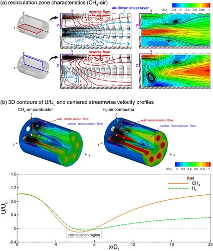
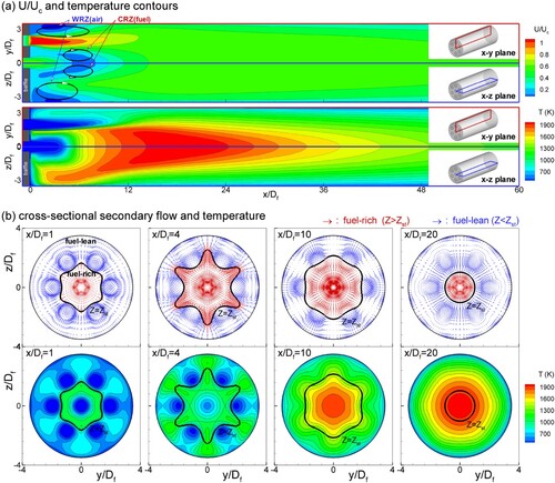
The developmental patterns of reacting flow can be examined by recirculating flows and temperature field. Figure shows streamwise velocity contours, velocity vectors, and temperature contours on the x–y and x–z planes. In Figure (a), the x–y plane passes through the air hole at z = 0, and the x–z plane is the side between the air holes at y = 0. Two large recirculation zones are observed. As can be seen, the wall recirculation zone is related to the air jets, and the center recirculation zone is formed in the fuel jet front. The flame zone starts at the beginning region of the center recirculation zone, and the maximum temperature region is formed a little downstream. The wall recirculation zone produces reversed air flows, and the fuel flow is bifurcated by the center recirculation zone toward the air flows. As the residence time and the reactant mixing is improved by this flow structure, the reacting region becomes an elongated candle flame. Therefore, the efficient mixing and combustion in the baffled micro combustor are significantly affected by wall and center recirculating regions behind the baffle plate. In particular, the center recirculation zone enhances the fuel–air mixing by promoting the movement of the fuel toward the air. In Figure (b), the stoichiometric mixture line of Z = Zst is plotted with temperature contours to see the flame structure. For various geometry and boundary conditions, the stoichiometric mixture fraction is generally adopted to interpret the flame structure in the Z space. Four axial positions of x/Df = 1, 4, 10, 20 are selected to check the flame development. The velocity vectors of secondary flows are classified into two parts. The red vectors represent the fuel-rich mixture of Z > Zst, which is originated from the fuel stream. And the blue vectors are the fuel-lean mixture of Z < Zst originated from the air stream. At x/Df = 1, the lobed Z = Zst line develops weakly. Since the axial position is very near the baffle, the secondary flows and the fuel-rich stream are weak. But the lobed features of the Z = Zst line and the fuel-rich stream are observed at x/Df = 4. This is considered that the lobed flame shape is actively developed. In the downstream x/Df = 10, the lobed flame is very weak, and after that, it is completely disappeared. These changes in the lobed Z = Zst line and the fuel-rich zone are attributed to the development of the wall and center recirculations. The lobed flame shape is roughly maximized at the streamwise position x/Df ≈ 4 corresponding to the center of the wall recirculation or the beginning of the center recirculation. When the wall recirculation zones develop, the spreading of the fuel-rich stream is enhanced than the case of no wall recirculations because the central stream tries to compensate for the mass reduction by the reversed flow of the wall recirculation. Also, as the center recirculation develops, the radially outward flow of the fuel-rich stream is enhanced. As a result, it can be comprehended that the lobed flame shape is developed. The lobed structure enhances the mixing of fuel and air due to the secondary flows of moving the air to the center of the combustion chamber and the fuel to the combustion chamber wall. The magnitude of such secondary flows is reduced while passing through the flame region, because the streamwise flow is accelerated across the flame region. Then, the lobed structure is weakened, and the cross-sectional flame shape is formed into a circular shape. Based on these characteristics, the baffle-induced lobed flame significantly influences the initial development of the flame zone. As a result, the developing pattern of the lobed flame is critical in altering the efficient combustion and heat transfer characteristics of the baffled micro combustor.
Figure 6. Velocity vectors and temperature contours (CH4–air, bt = 0.1Df) The black solid line represents Z = Zst.
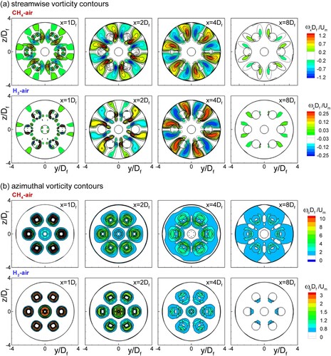
The secondary flows associated with the lobed structure in the cross-section of the combustion chamber can be examined by the streamwise and azimuthal vortices. In lobed jets, the flow mixing is improved by the increased such vortices (Hu et al., Citation2000, Citation2001, Citation2002). From a similar perspective, it is meaningful to examine the lobed structure and the related vortices. For reacting flows of CH4–air and H2–air, Figure shows the distribution of streamwise (ωx) and azimuthal vorticity (ωo = (ωy2 + ωz2) 1/2) on the y–z plane at x/Df = 1.0, 2.0, 4.0, and 8.0. In Figure (a), streamwise vortices are axially developed in the form of six pairs. At x/Df = 1.0, the high vorticity is concentrated near air holes. As the flow develops downstream, the region of the high vorticity is expanded toward the fuel hole and combustion chamber wall. In Figure (b), the high azimuthal vorticity at x/Df = 1.0 is mainly observed near the fuel and air holes. At x/Df = 2.0, 4.0, the azimuthal vorticity is more and more widely distributed around the holes. As a result of such changes, counter-rotating streamwise vortices are generated at x/Df = 2.0 and 4.0. These vortical motions are related to the wavy development of the stoichiometric mixture line. Regardless of the reaction type, the development pattern of streamwise and azimuthal vortices is almost similar, but the vortex intensity of CH4–air combustor is higher than that of H2–air combustor. Therefore, it can be considered that the vortical motions due to the multihole baffle increase with high fuel density.
Figure 7. Comparisons of streamwise and azimuthal vorticities at x/Df = 1.0, 2.0, 4.0, and 8.0 (bt = 0.1Df).
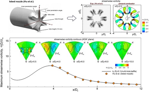
From the literature on the lobe jet (Cai et al., Citation2010; Hu et al., Citation2000, Citation2001, Citation2002; Paul et al., Citation2020), it is well known that the streamwise vortices in the lobe crest or trough have an important role in enhancing the flow mixing. The baffle-induced secondary flows are very similar to the flow structure of the lobed jet. However, the present lobed structure is generated by the momentum difference between fuel and air jets from the baffle hole and the baffle wall, unlike the vortices of the lobed jet due to the specific shape like the corrugated surface. As a result, secondary flows in the baffled micro combustor develop more slowly than secondary flows in the lobed jet. However, the lobed jet has the feature that the secondary flow immediately develops, because it is based on the specific nozzle. Considering this difference, the axial variation of the streamwise vorticity magnitude is compared to the experimental results of Hu et al. (Citation2000, Citation2001, Citation2002). The streamwise vorticity magnitude is an important feature representing the lobed flow structure, but it is difficult to directly compare the vorticity magnitude for different geometries. In Figure , non-dimensionalized vorticities are compared. It is based on that the axial development of the lobed flow is similar even if the lobed flow can be obtained from various methods. Although the production process of the lobed flow structure is different, the two results show that they have very similar developmental process. From the results, we understand that the baffle-induced lobed flow has a secondary flow structure that is very similar to the lobed jet.
Figure 8. Streamwise vorticity magnitude variation with streamwise vorticity contours of AOA’ plane (CH4–air, bt = 0.1Df).
3.2. Development of lobed flames
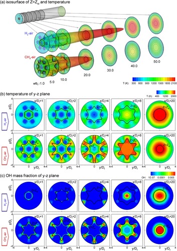
To examine the development of lobe flame structure, in Figure , contours of temperature and OH mass fraction at several streamwise locations are plotted with isosurfaces of Z = Zst. The black line of Z = Zst is inserted in the contour plots. In general, the high-temperature zone and the large OH (hydroxyl radical) mass fraction are formed near the stoichiometric condition of Z = Zst. The large OH mass fraction represents the front flame region with the peak temperature. Therefore, the change of the flame shape can be analyzed by the pattern of the Z = Zst line and the distribution of the OH mass fraction. In the figure, the flame length and the flame surface are understood by the isosurface of Z = Zst. The flame length of CH4–air is decreased to 60% in the flame length of H2–air. As shown in Figure , the CH4–air case has a larger center recirculation than the H2–air case. The center recirculation induces the movement of the fuel toward the air. Eventually, the fuel–air mixing gets faster and the flame length decreases due to the increased center recirculation. The change of the center recirculation zone is strongly dependent on the baffle hole conditions of diameter, shape, and position (Kim & Park, Citation2018). For example, when the air hole position (ra) changes, the flame length of the 2ra/D = 0.643 case is reduced to 58% of the 2ra/D = 0.429 case. And, the triangular hole baffle induces a 40% reduced flame length compared to the circular hole baffle. In the present result, two fuel types of CH4 and H2 are compared under the same baffle plate. Interestingly, the flame length change due to the fuel type is comparable to the flame length reduction according to the geometrical change of the baffle plate. In Figure (b), it is confirmed that the flame shape of the Z = Zst line becomes a lobed structure. In the lobed Z = Zst line, as the distance difference between crest and trough increases, it can be determined that the lobed flame is enhanced. For the CH4–air flame, such difference is more severe than that of the H2–air flame at the same streamwise position. Also, the reaction zone is checked from the radical distributions of OH in Figure (c). In the reactive zone, radicals are created to maintain the chemical reactions, and the reaction heat is emitted with the recombination reactions using the radicals. The Z = Zst line represents the boundary of the high-temperature zone, and the large mass fraction of OH is observed in the high-temperature region. As can be seen, the radical mass fractions increase near the crest of the Z = Zst line, and the temperature increase. Based on these features, the baffle-induced lobed flame can be identified. However, we conclude that the analysis of the lobed flame is appropriate to be based on the Z = Zst line because it is difficult to determine the flame boundary by the distributions of temperature and radical.
Figure 9. Temperature contours at several streamwise locations with iso-surface contour of Z = Zst (CH4–air and H2–air, bt = 0.1Df).
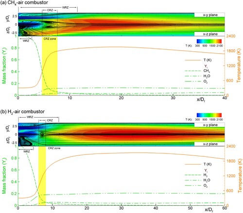
For reacting flows, the change of the flow structure mixes the fuel and air differently, and the different reactions are eventually obtained. Such variations of reacting flows are reflected in the distributions of temperature and mass fractions of reactants and products. Figure shows axial distributions of temperature and mass fractions of reactants and products. To help the understanding of axial temperature variations, streamlines in the x–y and x–z planes are added with temperature contours. Based on the temperature rise, the combustion reaction is slowly initiated at x/Df = 2–4. This location is consistent with the position where the streamwise and azimuthal vorticity distributions begin to become the lobed pattern (See Figures and ). After passing through the location, the temperature drastically increases because of the increased reaction rate. As can be seen, the CH4 consumption is axially faster than the H2 consumption. For the H2–air case, the radial flow development and the reactant mixing become weak because of the reduced center recirculation zone. As a result, the H2–air case is less activated, and the reaction zone is positioned further downstream than that of the CH4–air. The steep increase of temperature appears at x = 4–6 Df for the CH4–air case and x = 4–10 Df for the H2–air case. These regions approximately correspond to the axial position of the center recirculation. For different fuel types, the wall recirculation size is weakly changed, but the center recirculation is more severely changed. The change of the center recirculation zone depending on the fuel property is comparable to the variation due to the geometrical change of the baffle plate (Kim & Park, Citation2018, Citation2019). Therefore, it is considered that the center recirculation has a crucial role in the change of combustion characteristics. In this sense, the lobed flame structure is strongly influenced by the development of the center recirculation.
Figure 10. Axial distributions of temperature and mass fractions of reactants and products (CH4–air and H2–air, bt = 0.1Df).
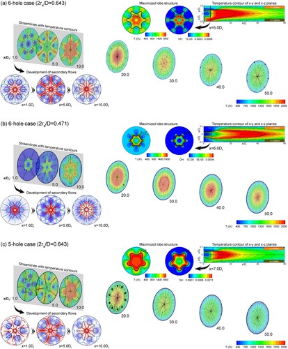
In a baffled combustor, the production of recirculating flows depends on the geometrical conditions of the baffle plate, and different recirculations are closely related to changes in the lobed flow structure. Among the geometrical variables, when the air hole position (ra) and the number of air holes change, the distributions of temperature and OH mass fraction and streamlines of secondary flows are compared in Figure . To see the development of the lobed flame shape, the fuel-lean regions of Z < Zst and the fuel-rich regions of Z > Zst are plotted by blue and red vectors, respectively. When ra changes, the lobed flame structure is enhanced for the 2ra/D = 0.643 case than the 2ra/D = 0.471 case. For the 2ra/D = 0.471 case, the fuel-lean region increases and the flame length is reduced due to the degraded mixing efficiency. Meanwhile, the number of air holes is changed. The 5-hole case is developing the lobed flame structure just like the 6-hole case. Compared to the maximized lobe shape, the wavy shape of the lobe is sharp for the 6-hole case, whereas it is blunt for the 5-hole case. However, the region satisfying the Z = Zst condition for the 5-hole case is more than the 6-hole case at the same streamwise location. This means that the well-mixed state is quickly obtained for the 5-hole case. It is confirmed by the flame length comparison. Considering the well-mixed state, getting the Z = Zst condition in as many places as possible is better. Therefore, the lobed Z = Zst line represents a well-mixed mixture for efficient combustion than the circular Z = Zst line. Based on flow characteristics, the different lobes of the lobed Z = Zst line can be obtained when the number of air holes is changed. But many lobes do not necessarily indicate a well-mixed state because the difference between crest and trough of the lobed Z = Zst line may be small. Therefore, an appropriate parameter representing such a situation needs to be defined.
Figure 11. Streamlines, velocity vectors, and contours of temperature and OH mass fraction for different baffle conditions (CH4–air, bt = 0.1Df).
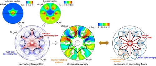
From a closer inspection of Figures – and , the mixing structure of fuel and air is systematically explained in Figure . In the present combustor, the fuel hole is located at the center of the baffle plate, and six air holes surround it. The fuel–air mixing and the corresponding mixture fraction are determined by the geometrical feature of the baffle plate. The lobed shape of the Z = Zst line, i.e. lobed stoichiometric line or lobed flame, is observed due to the interaction of radially outward fuel flow and inward airflow. As can be seen, the lobed Z = Zst line has six crests and troughs because the baffle has six air holes. As discussed in Figure , if the number of air holes changes, the number of crests and troughs will be changed by it. The secondary flows are divided into a fuel-rich stream of red vectors and a fuel-lean stream of blue vectors, as shown in Figures and . First, between the air jets and the combustion chamber wall, recirculating wall flows are created. Due to the constraint of the baffle plate and combustion chamber walls, reversed flows produce radially inward flows. The fuel jet exhibits azimuthally differing spreading rates in the interval region of air jets and non-air jets. In the azimuthal interspace of air jets, the radial spreading of the fuel jet is more free because the influence of the air jets is small. Therefore, as the fuel stream is pushed to the combustion chamber wall, the radial outflows are developed between air holes, and the crest pattern of the lobed structure is obtained. Because of this flow, the inward flows near the air jets become stronger than those of the azimuthal region between air jets. As a result, the trough pattern of the lobed structure is obtained. Based on these flow structures, the flows pushed out of the crests are directed to the air holes, and the counter-rotating vortex pairs are generated near both sides of crests. Since the production of the lobed flame structure is mainly attributed to the radially outward motion of the fuel stream, the existence of the center recirculation zone is highly critical to the development of lobed flame. The above pattern of secondary flows and six pairs of counter-rotating streamwise vortices are confirmed from the velocity vectors and contours of streamwise vorticity. Comparing the CH4–air case to the H2–air case, the lobed structure is significantly developed, and the streamwise vorticity is enhanced. However, their overall feature is commonly observed regardless of the fuel type. Therefore, the lobed flame can be considered as a typical feature of the multihole baffled micro combustor.
Figure 12. Schematic of secondary flows, velocity vectors, and streamwise vorticity contours.
3.3. Shape parameter of lobed flame
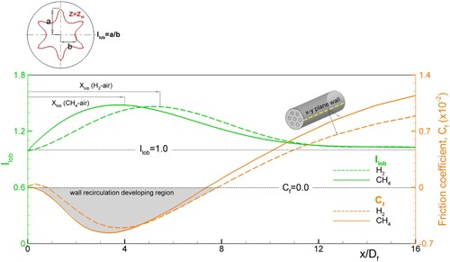
The lobed flow and flame development are closely related to the variation of recirculating flows in the combustion chamber. For bt/Df = 0.1, Figure shows the relation between the axial change of the lobed flame and wall friction coefficient on the combustion chamber. To quantify the lobed flame structure, the lobe intensity Ilob is newly defined for the lobed stoichiometric line. Here, Ilob = a/b, where a and b are radii to the crest and the trough of the lobed Z = Zst line, respectively. Also, we can determine the size of the wall recirculation zone from the negative region of the wall friction coefficient. From the Ilob definition, the increased Ilob means an enhanced lobed shape, while Ilob = 1 represents a non-lobed case of circular shape. Ilob increases to x/Df = 4.0–5.0, then decreases. Most changes of Ilob are occurring in the region of x/Df < 8.0 where the wall recirculation is developing. Based on the characteristics of Ilob change, the lobed position Xlob is defined, and the maximum lobe intensity Ilob,max is obtained. Xlob is estimated from the axial position of the maximum lobe intensity. The maximum lobe intensity is quickly obtained for the CH4–air case with a larger center recirculation than the H2–air case. That is, Xlob ≈ 4.0 Df for CH4–air and Xlob≈ 5.4 Df for H2–air. For the H2–air case, Xlob is shifted downstream compared to that of the CH4–air case, but there is little change in the sizes of the wall recirculation. Comparing Xlob to the recirculation zones in Figures and , the position is roughly consistent with the middle of wall recirculation and the beginning region of center recirculation. In terms of reacting flows, Xlob is important because the active reaction can be started at the position. In Figure , it is found that Xlob is approximately matched to the positions of x ≈ 3.3 Df for CH4–air and x ≈ 4.5 Df for H2–air where temperatures start to rise sharply. From this result, Ilob and Xlob are considered as meaningful factors representing combustion characteristics in the multihole baffled micro combustor.
Figure 13. Comparisons of lobe intensity and wall friction coefficient (CH4–air and H2–air, bt = 0.1Df).
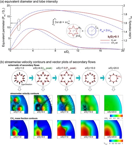
For efficient combustion, it is necessary to obtain a lot of Z = Zst regions inside the combustion chamber. From this sense, the lobed stoichiometric line shows that the mixture is close to a well-mixed state than the circular stoichiometric line in the cross-section of a combustor. As discussed previously, the shape of the lobed flame depends on the number of air holes. The maximized Ilob is close to a well-mixed mixture, but it may not represent the best condition for Z = Zst. Therefore, to quantify the Z = Zst region, the equivalent perimeter of the lobed Z = Zst line is introduced as Peq = 2πreq. The req value is obtained by the area integral.
(9)
(9)
Here
means the radius of the Z = Zst line. After the Z > Zst area surrounded by the Z = Zst line is numerically integrated, the equivalent radius req and perimeter Peq are calculated. The high Peq represents a better mixing of reactants regardless of the Z = Zst shape. Figure shows the evolution of the equivalent perimeter and the secondary flows based on the lobe intensity. As the secondary flow develops, the lobed structure is initiated near the baffle plate. The secondary flow becomes stronger as it goes downstream. The resulting Z = Zst line is radially expanded and the lobe intensity is enhanced. For the CH4–air case, the lobe intensity is maximized at x/Df = 3.8, i.e. Xlob/Df = 3.8, but
is maximized at x/Df = 7. The two positions are differently observed. From the baffle shape feature, the central jet dominates the radial expansion of the lobed Z = Zst line. Accordingly, as the lobe intensity or the radial expansion of the Z = Zst line increases, Peq increases. If there is no radial expansion of the Z = Zst line, Peq is maximized at Xlob because the lobe intensity is a quantitative expression of the wavy Z = Zst line. However, the peak Peq is obtained after the lobe intensity is the maximum value. Therefore, it is considered that Peq is more largely influenced by the radially outward fuel flow. The maximum of Peq represents a well-mixed state of reactants, and its axial position is the place where the reaction is maximized. As can be seen in Figure , the position coincides with the location having the maximum temperature. Also, the location is almost identical to the end of the center recirculation region. After passing through Xlob, the flow is further developed in an axial direction, and the lobe intensity is reduced. Finally, the Z = Zst line becomes a circle. From a detailed comparison of Figures and , Xlob is close to the beginning of the flame zone, and the position of the peak Peq is related to the location after the temperature rises sharply. Therefore, the positions are useful to find the region of high wall heat flux.
Figure 14. Evolution of the lobed structure and secondary flows.
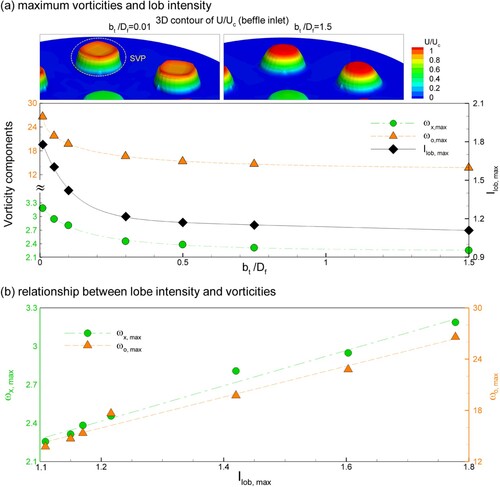
In the current baffled micro combustor, the lobed structure can be obtained by changing the baffle shape. One of the possible methods is to change the baffle thickness while fixing other shape conditions. As discussed earlier, the lobed flow structure is related to the variation of radial flows depending on the center and wall recirculations development. From Kim and Park (Citation2019), the vortical structures are differently obtained for the inflow type of a sharp-edged orifice and a long pipe. For the baffled micro combustor, this situation is realized by variable baffle thickness. The jet flow through the baffle hole represents characteristics of an orifice type as the baffle thickness lowers. With increasing baffle thickness, however, it becomes the feature of fully developed pipe flows. By this background, the vorticity magnitude and the lobe intensity are examined for seven different baffle thicknesses. For the CH4–air case, Figure shows the magnitudes of maximum vorticities (ωx,max, ωo,max) at the baffle exit and Ilob,max for different baffle thicknesses. The streamwise velocity contours for bt/Df = 0.01 and 1.5 are added in the figure. For bt/Df = 0.01, the velocity profile has off-centered peaks called the saddle-shaped profile. It is because the flow passage is abruptly reduced, and its length is short. At the same time, the velocity profile for bt/Df = 1.5 shows a typical feature of pipe flow. As bt/Df decreases, Ilob,max and vorticity magnitudes increase. For bt/Df > 0.5, the values converge to constants. Compared to the thin baffle of bt/Df = 0.01, the vorticity values of bt/Df = 1.5 are 60%–70%. Similarly, Ilob,max of bt/Df = 1.5 decreases to 60% for the thin baffle of bt/Df = 0.01. Therefore, it can be understood that the reduction of baffle thickness produces the vortical flows promoting the lobed structure generation, and the realization of the orifice flow from the baffle plate is possible for bt/Df < 0.5. Also, in Figure (b), ωx,max and ωo,max have the linear relation for Ilob,max. This means that that there is a close relationship between the maximum vorticities (ωx,max, ωo,max) at the baffle exit and the maximized lobe structure. Generally, when the vortical structures are enhanced in the combustion chamber, the mixing of fuel and oxidizer is improved. From the above similarity, it can be seen that the mixing structure for reacting flows is examined in terms of Ilob,max.
Figure 15. Variation of maximized vorticities and Ilob for different baffle thickness (CH4–air).
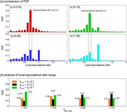
To see the mixing performances for different baffle thicknesses, Figure (a) shows probability density function (PDF) of the local equivalence ratio for the range of 0≤
≤2.0, when
= 0.7.
is related to the local mixture fraction.
(10)
(10) As can be seen, the local equivalence ratio of 0.7≤
≤0.75 is frequently observed for bt/Df = 0.01, 0.1, 0.5, and 1.5. It depends on the inlet condition of
= 0.7. As bt increases, the PDF value decreases for 0.7≤
≤0.75 and more enhanced for
= 1.0. For a well-mixed condition, the probability density function becomes the single mode of
=
. However, since the present baffled combustor is a non-premixed type, the PDF distributions of
depending on the fuel–air mixing. To examine the mixing characteristics, the probability distributions for different baffle thicknesses are divided into three parts:
<0.7, 0.7≤
≤0.75, and
>0.75. Figure (b) represents the summated probability densities for different Ilob,max. As Ilob,max decreases, the center parts decrease and the off-center parts are increased. From these results, the high Ilob,max case has a good mixing performance, whereas the performance is reduced with decreasing Ilob,max and the mixture becomes fuel-rich states.
Figure 16. Comparison of probability density distributions of and the summated PDF.
3.4. Energy conversion characteristics
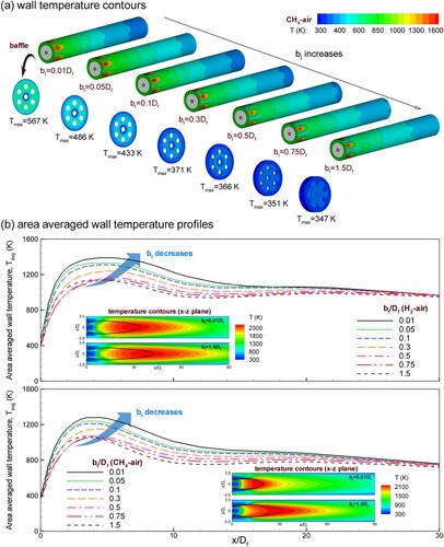
For micropower devices, the energy conversion media of a thermal emitter and n- and p-type semiconductors are installed to use the wall heat transfer. Most such systems require high wall temperature to increase the system performance. In particular, the TPV system uses a conversion process from heat to electricity via photons. If the high wall temperature maintains, the photon emission through the radiative heat transfer of the thermal emitter becomes active. Temperature contours of the baffle plate and the combustion chamber wall, the azimuthally area-averaged wall temperature, and temperature contours of the x–z plane are plotted in Figure to investigate such characteristics. In the temperature contour plot of the x–z plane, the stoichiometric condition of Z = Zst is represented by the black line.
(11)
(11) where Aw and Tw are the surface area and temperature on the outer combustor wall. The azimuthal Aw and Tw at the axially same grid cell are used for Tavg. In Figure (a), the wall temperatures are azimuthally distributed in a wavy form. The high temperature regions are consistent with the number of crests in the lobe structure. As bt increases, the size of the high temperature region and the baffle temperature are reduced by the axially elongated flame. Since the fuel and air of 300 K flow into the combustion chamber, the preheating effect of the baffle plate is confirmed. The preheating effect is more enhanced for the thin baffles. This feature is reflected in the averaged wall temperature of Figure (b). That is, as bt increases, the averaged wall temperature is decreased. And, it is large in the region where the lobe structure is dominant. Regardless of the fuel type, the axial variation of the area-averaged wall temperature is almost similar for decreasing bt. But, the temperature values of the H2–air case are larger than those of the CH4–air case. It is because the H2–air case has a longer flame zone. For example, in the case of bt/Df = 0.01, the flame length of the H2–air case is increased to 180% of the CH4–air case. For a micro combustor, the short flame length is better to get efficient combustion. However, the proper long flame is required to improve energy conversion even if the combustion efficiency is reduced.
Figure 17. Temperature contours and azimuthally averaged wall temperatures for different bt.
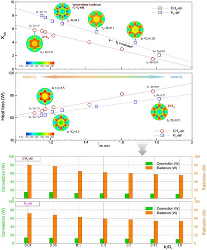
Further analysis is performed to examine the relationship between the lobe structure and variables representing the reacting flows for the flame length, heat loss, and energy conversion rate. In Figure , Xlob and the heat loss are plotted for different Ilob,max. Here, the heat loss q is estimated by the sum of convective (qconvection) and radiative (qradiation) heat transfer through the outer combustor wall from inside the combustion chamber to the ambient.
Figure 18. Variations of maximized Ilob location and heat loss depending on Ilob, max.
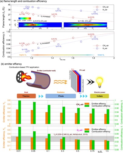
For the H2–air and CH4–air cases, Figure shows the variation of the flame length, the combustion efficiency (η), and the emitter efficiency (ηe) for different bt/Df. Here, two efficiencies are defined as
(13)
(13)
(14)
(14) where Yf,in and Yf,out are the mass fraction of inlet and outlet (Akhtar et al., Citation2019; Kim & Park, Citation2019) and LHV is fuel's lower heating value. For a TPV system, the combustion heat is absorbed into the PV cells in the radiative heat transfer because the photons are promoted by the thermal radiation. On the basis of this, the radiative heat transfer qradiation is used for Equation (14). As Ilob,max increases, the lobed shape is enhanced, the flame length decreases, and the combustion efficiency increases. The increased Ilob,max can give the better mixing for efficient combustion. Therefore, when Ilob,max gets larger, the flame length decreases, and higher η is obtained. As shown in Figure , the lobe intensity is enhanced for lower bt cases. From the result, more efficient combustion is obtained for lower bt cases. The flame zone with active reaction rate is described by the distribution of the OH radical. The flame patterns are compared for two CH4–air combustors with different baffle thicknesses. The reaction zone of bt/Df = 0.01 is formed than the bt/Df = 1.5 case in the front region. It is related that the thin baffle promotes the vortical flows and the lobe intensity. In Figure (b), as the combustion efficiency get betters, the emitter efficiency is improved. The emitter efficiency of the present baffled micro combustor is similar to or better than the micro combustor of Akhtar et al. (Citation2019). For the H2–air combustor, when bt/Df < 0.1, the emitter efficiency is ηe = 0.319–0.326. When baffle thickness changes, the emitter efficiency of the CH4–air combustor is 14.3–25.9% higher than that of the H2–air combustor. These results confirm that the thin baffle is favorable for efficient combustions in the baffled micro combustor.
Figure 19. Variations of flame length and conversion rate depending on Ilob, max.
4. Conclusions
For a multihole baffled micro combustor with a mixed feature of bluff body and multiple jets, the influence of lobe structure on reacting flows is numerically investigated by the detailed chemistry kinetics for CH4–air and H2–air. From the model tests, it is considered that the combination of RSM and the GRI-Mech 3.0 mechanism is suitable for capturing the multihole effect on reacting flows in the baffled micro combustor. Flow and combustion characteristics for various baffle thicknesses and fuel properties are investigated by the numerical procedure.
Regardless of the fuel type, the recirculation zones and the lobed flame shapes are variously formed for the baffle thicknesses. The lobed structure of several crests and troughs related to air holes is strengthened at the streamwise position near the beginning of center recirculation. The counter-rotating vortex pairs are generated near both sides of crests. They enhance the flows of moving the air to the center of the combustion chamber and the fuel to the combustion chamber wall. Such secondary flows are similar to the flow structure of the lobed jet or nozzle. After the lobe structure is weakened and the reactant mixing is terminated, the maximum temperature is obtained.
To characterize the lobed structure of reacting flows, the lobe intensity Ilob and the equivalent perimeter Peq of the lobed Z = Zst line are newly defined. The maximum Ilob is observed at the beginning position of the flame zone, its change is related to the wall heat transfer rate. A close relationship between the maximum vorticities at the baffle exit and the maximized lobe structure is also confirmed. When Peq becomes maximum, the temperature rises sharply. Such positions are useful to find the region of high wall heat flux. The enhanced lobe structure is not desirable due to the increased radiative heat transfer, but it is a good feature for a micro-device such as TPV and TEG system.
As the lobe intensity increases, the flame length decreases, and the combustion efficiency is increased. Although the short flame length is better for efficient combustions, it is observed that the longer flame is a good feature for energy conversion. For a micro-TPV system, the radiative heat transfer through the combustor wall is 5 times larger than the convective heat transfer. For bt/Df < 0.1 showing the strong lobe structure, the emitter efficiency of energy conversion is obtained as ηe = 0.319–0.326 for the H2–air combustor. The efficiency is increased by 26% for the CH4–air combustor. The results confirm that the multihole baffled micro combustor can be efficiently utilized for an energy conversion device through the baffle shape change.
Disclosure statement
No potential conflict of interest was reported by the author(s).
Additional information
Funding
References
- Akhtar, S., Kurnia, J. C., & Shamim, T. (2019). A three-dimensional computational model of H2–air premixed combustion in non-circular micro-channels for a thermo-photovoltaic (TPV) application. Applied Energy, 152, 47–57. https://doi.org/10.1016/j.apenergy.2015.04.068
- ANSYS 13.0 user's guide. (2006). Fluent Inc.
- Bagheri, G., Hosseini, S. E., & Wahid, M. A. (2014). Effects of bluff body shape on the flame stability in premixed micro-combustion of hydrogen-air mixture. Applied Thermal Engineering, 67(1–2), 266–272. https://doi.org/10.1016/j.applthermaleng.2014.03.040
- Cai, J., Tsai, H. M., & Liu, F. (2010). Numerical simulation of vortical flows in the near field of jets from notched circular nozzles. Computers and Fluids, 39(3), 539–552. https://doi.org/10.1016/j.compfluid.2009.10.006
- Choi, H. S., & Park, T. S. (2009). A numerical study for heat transfer characteristics of a micro combustor by large eddy simulation. Numerical Heat Transfer, Part A: Applications, 56(3), 230–245. https://doi.org/10.1080/10407780903163470
- Choi, H. S., Park, T. S., & Suzuki, K. (2008). Turbulent mixing of a passive scalar in confined multiple jet flows of a micro combustor. International Journal of Heat and Mass Transfer, 51(17–18), 4276–4286. https://doi.org/10.1016/j.ijheatmasstransfer.2007.12.017
- Chou, S. K., Yang, W. M., Chua, K. J., Li, J., & Zhang, K. L. (2011). Development of micro power generators – a review. Applied Energy, 88(1), 1–16. https://doi.org/10.1016/j.apenergy.2010.07.010
- Espinoza-Jara, A., Walczak, M., Molina, N., Jahn, W., & Brevis, W. (2022). Erosion under turbulent flow: A CFD-based simulation of near-wall turbulent impacts with experimental validation. Engineering Applications of Computational Fluid Mechanics, 16(1), 1526–1545. https://doi.org/10.1080/19942060.2022.2099978
- Fan, A., Wan, J., Maruta, K., Yao, H., & Liu, W. (2013). Interactions between heat transfer, flow field and flame stabilization in a micro-combustor with a bluff body. International Journal of Heat and Mass Transfer, 66, 72–79. https://doi.org/10.1016/j.ijheatmasstransfer.2013.07.024
- Fernandez-pello, A. C. (2002). Micropower generation using combustion: Issues and application. Proceedings of the Combustion Institute, 29(1), 883–899. https://doi.org/10.1016/S1540-7489(02)80113-4
- Giovangigli, V., & Smooke, M. D. (1987). Extinction of strained premixed laminar flames with complex chemistry. Combustion Science and Technology, 53(1), 23–49. https://doi.org/10.1080/00102208708947017
- Hu, H., Saga, T., Kobayashi, T., & Taniguchi, N. (2000). Research on the vortical and turbulent structure in the lobed jet flow using fluorescence and particle image volocimetry techniques. Measurement of Science Technology, 11(6), 698–711. https://doi.org/10.1088/0957-0233/11/6/313
- Hu, H., Saga, T., Kobayashi, T., & Taniguchi, N. (2001). A study on a lobed jet mixing flow by using stereoscopic particle image velocimetry technique. Physics of Fluids, 13(11), 3425–3441. https://doi.org/10.1063/1.1409537
- Hu, H., Saga, T., Kobayashi, T., & Taniguchi, N. (2002). Mixing process in a lobed jet flow. AIAA Journal, 40(7), 1339–1345. https://doi.org/10.2514/2.1793
- Jones, W. P., & Lindstedt, R. P. (1988). Global reaction schemes for hydrocarbon combustion. Combustion and Flame, 73(3), 233–249. https://doi.org/10.1016/0010-2180(88)90021-1
- Khalil, H. M., Eldrainy, Y. A., Abdelghaffar, W. A., & Abdel-Rahman, A. A. (2019). Increased heat transfer to sustain flameless combustion under elevated pressure conditions – a numerical study. Engineering Applications of Computational Fluid Mechanics, 13(1), 782–803. https://doi.org/10.1080/19942060.2019.1645737
- Kim, W. H., & Park, T. S. (2018). Non-premixed lean flame characteristics depending on air hole positions in a baffled micro combustor. Applied Thermal Engineering, 129, 431–445. https://doi.org/10.1016/j.applthermaleng.2017.10.064
- Kim, W. H., & Park, T. S. (2019). Flame characteristics depending on recirculating flows in a non-premixed micro combustor with varying baffles. Applied Thermal Engineering, 148, 591–608. https://doi.org/10.1016/j.applthermaleng.2018.11.075
- Kim, W. H., & Park, T. S. (2020). Influence of inlet vorticity and aspect ratio on axis switching and mixing characteristics of heated rectangular jets. International Journal of Heat and Mass Transfer, 155, Article 119813. https://doi.org/10.1016/j.ijheatmasstransfer.2020.119813
- Kim, W. H., & Park, T. S. (2021). Inflow characteristics for generating axis-switching phenomenon of heated rectangular jets. Computers and Mathematics with Applications, 86, 73–89. https://doi.org/10.1016/j.camwa.2021.02.001
- Kim, W. H., & Park, T. S. (2022). Effects of number of air holes on flame and heat transfer characteristics in a multihole baffled combustor combined with micro-thermophotovoltaic and micro-thermoelectric systemsmicro can combustor with a seven-hole baffle. Applied Thermal Engineering, 208, Article 118180. https://doi.org/10.1016/j.applthermaleng.2022.118180
- Kuo, C. H., & Ronney, O. D. (2007). Numerical modeling of non-adiabatic heat-recirculating combustors. Proceedings of the Combustion Institute, 31(2), 3277–3284. https://doi.org/10.1016/j.proci.2006.08.082
- Mi, J., & Nathan, G. J. (2010). Statistical properties of turbulent free jets issuing from nine differently-shaped nozzles. Flow, Turbulence and Combustion, 84(4), 583–606. https://doi.org/10.1007/s10494-009-9240-0
- Paul, R. V., Kriparaj, K. G., & Tide, P. S. (2020). Numerical predictions of the flow characteristics of subsonic jet emanating from corrugated lobed nozzle. Aircraft Engineering and Aerospace Technology, 92(7), 955–972. https://doi.org/10.1108/AEAT-03-2019-0041
- Sheng, Z., Huang, P., Zhao, T., & Ji, J. (2015). Configurations of lobed nozzles for high mixing effectiveness. International Journal of Heat and Mass Transfer, 91, 671–683. https://doi.org/10.1016/j.ijheatmasstransfer.2015.08.022
- Smith, G. P., Golden, D. M., Frenklach, M., Moriarty, N. W., Eiteneer, B., Goldenberg, M., Bowman, C. T., Hanson, R. K., Song, S., Gardiner, W. C., Jr., Lissianski, V. V., & Qin, Z. (1999). GRI-Mech 3.0. http://www.me.berkeley.edu/gri_mech
- Smith, L. L., Majamaki, A. J., Lam, I. T., Delabroy, O., Karagozian, A. R., & Marble, F. E. (1997). Mixing enhancement in a lobed injector. Physics of Fluids, 9(3), 667–678. https://doi.org/10.1063/1.869224
- Sui, C., Zhang, J., Zhang, L., Hu, X., & Zhang, B. (2021). Large eddy simulation of premixed hydrogen-rich gas turbine combustion based on reduced reaction mechanisms. Engineering Applications of Computational Fluid Mechanics, 15(1), 798–814. https://doi.org/10.1080/19942060.2021.1918581
- Veríssimo, A. S., Rocha, A. M. A., Coelho, P. J., & Costa, M. (2015). Experimental and numerical investigation of the influence of the air preheating temperature on the performance of a small-scale mild combustor. Combustion Science and Technology, 187(11), 1724–1741. https://doi.org/10.1080/00102202.2015.1059330
- Waitz, I. A., Gauba, G., & Yang, S. T. (1998). Combustors for micro-gas turbine engines. Journal of Fluids Engineering, 120(1), 109–117. https://doi.org/10.1115/1.2819633
- Wan, J. A., Fan, W., Liu, Y., Yao, H., Liu, W., Gou, X., & Zhao, D. (2015). Experimental investigation and numerical analysis on flame stabilization of CH4/air mixture in a mesoscale channel with wall cavities. Combustion and Flame, 162(4), 1035–1045. https://doi.org/10.1016/j.combustflame.2014.09.024
- Westbrook, C. K., & Dryer, F. L. (1981). Simplified reaction mechanism for oxidation of hydrocarbon. Combustion Science and Technology, 27(1–2), 31–43. https://doi.org/10.1080/00102208108946970
- Yang, B., & Pope, S. B. (1998). An investigation of the accuracy of manifold methods and splitting schemes in the computational implementation of combustion chemistry. Combustion and Flame, 112(1–2), 16–32. https://doi.org/10.1016/S0010-2180(97)81754-3
- Yang, W. M., Chua, K. J., Pan, J. F., Jiang, D. Y., & An, H. (2014). Development of micro-thermophotovoltaic power generator with heat recuperation. Energy Conversion and Management, 78, 81–87. https://doi.org/10.1016/j.enconman.2013.10.040
- Zhang, L., Zhu, J., Yan, Y., Guo, H., & Yang, Z. (2015). Numerical investigation on the combustion characteristics of methane/air in a micro-combustor with a hollow hemispherical bluff body. Energy Conversion and Management, 94, 293–299. https://doi.org/10.1016/j.enconman.2015.01.014