
 ?Mathematical formulae have been encoded as MathML and are displayed in this HTML version using MathJax in order to improve their display. Uncheck the box to turn MathJax off. This feature requires Javascript. Click on a formula to zoom.
Abstract
The majority of facilities installed in offshore oil and gas fields during the 1980s and 1990s were designed to operate in ‘normal’ conditions. However, during the operational life of the fields, some new high pressure/high temperature (HPHT) wells may be discovered and tied back to older facilities. Operating these facilities beyond their design parameters in harsh environments may lead to catastrophic failures, resulting in significant economic losses and environmental problems. Managing the risks associated with failure of ageing subsea facilities in HPHT environments is considered as a very complex and critical task. To overcome such challenge, there is a need for development of decision-making methods that are capable of estimating precisely the risks associated with HPHT conditions as well as prioritising the risk mitigation and remediation strategies. This paper aims to propose an integrated risk management framework – based on Failure Mode and Effects Analysis (FMEA) approach and a hybrid Multi-Criteria Decision Analysis (MCDA) model – for evaluating the risks and prioritising mitigation strategies over the extended lifetime of subsea facilities in HPHT environments. For the purpose of illustrating the model, a case study of subsea manifold and flowlines is provided and the results are evaluated and discussed. Our findings indicate that the proposed approach offers significant improvement to the classical risk management processes applied to subsea oil and gas facilities as it can assist asset managers, risk analyst, regulators and policy makers with a decision model which considers both subjective (qualitative) judgements and objective (quantitative) evaluation measures.
1. Introduction
The continued operation of facilities beyond their original design lifetime, instead of investing in new facilities, is one of the hottest topics in the offshore oil and gas industry. Asset integrity audits conducted by the UK health and safety executive (HSE) (https://www.hse.gov.uk/) indicate that offshore oil and gas installations are designed for an expected lifetime of 25 years, and when they reach the end of their useful life a decision must be taken by operators as whether to decommission and replace components by new ones or go through life extension programs.
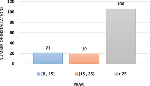
Life extension of ageing facilities is receiving an increasing attention from the offshore oil field operators, service providers, and environmental protection agencies (Shafiee and Animah, Citation2017; Animah et al., Citation2018). By the end of 2003, almost half of the fixed platforms operating in the Norwegian Continental Shelf (NCS) and the United Kingdom Continental Shelf (UKCS) exceeded their original design life. The Draugen oil field in the Norwegian Sea has recently received consent from the Petroleum Safety Authority (PSA) to continue operation of the facilities until 2023 (https://www.norskpetroleum.no/en/facts/field/draugen/). Equinor, formerly Statoil, has also launched a programme to extend the late life of Troll A platform from 2045 to 2063 (https://www.oilandgaspeople.com/news/). A significant number of oil platforms and subsea equipment in the Brazilian Northeast are near (or have exceeded) the end of their lifecycle. Figure shows a bar chart representing the age of offshore oil and gas production facilities installed in Brazil by the end of 2015. As can be seen, 106 facilities out of the total of 146 (i.e. about 73% of the total number of installations) are nearly beyond their 25-year life expectancy.
Figure 1. Distribution of the age of offshore oil and gas production facilities in the Brazilian Northeast by the end of 2015 (Pires et al., Citation2016).
Although extending the operational lifetime of offshore oil and gas facilities may be technically feasible, continuing in service beyond original design life can be unsafe and result in catastrophic failures, causing significant production losses and/or safety risks (Animah and Shafiee, Citation2018). Moreover, during the extended life of operation, some new high pressure/high temperature (HPHT) wells may be discovered and tied back to older facilities in order to improve their performance. This can create significant risks and great challenges for the operation of offshore oil and gas fields, since majority of the old facilities have been designed for ‘normal’ working conditions, and therefore, they might be unable to withstand HPHT conditions during the life extension period.
A failure in offshore oil and gas facilities under HPHT conditions would lead to more disastrous consequences than under normal conditions. The risks associated with the operation of ageing subsea facilities in HPHT environments include the risk of equipment failure, safety hazards to personnel who work on platforms, and environmental risks such as pollution and site contamination. The equipment failure may be due to operational failure of well control systems, malfunctioning of subsea components due to harsh working conditions, progressive degradation, etc. The occurrence of any equipment failure could result in significant loss of revenues in the near and mid-term and ultimately reputational damage that can have a long term financial impact. Therefore, there is a critical need to reduce the likelihood as well as the magnitude of potential risk events associated with failure of subsea facilities operating under HPHT conditions during their extended life of operation.
According to Azouz (Citation2010), one of the plausible ways to overcome the challenges of operation in HPHT environments is to evaluate all the risks involved in failure of critical facilities and select the most suitable strategy for mitigating these risks. For this reason, it is required to develop an integrated risk management plan that can help asset managers prevent disastrous consequences of failures in ageing facilities under HPHT conditions – while simultaneously complying with high safety and environmental standards. An integrated risk management plan (that includes risk identification, risk analysis, risk evaluation and risk response planning) not only reduces or eliminates the negative consequence of failures but also would lead to an increased production output and reduced operation and maintenance (O&M) costs. Shafiee (Citation2015) indicated that the selection of risk response policy is a typical multiple-criteria decision analysis (MCDA) problem as various factors need to be considered simultaneously. To solve such problem, the decision makers require to evaluate risk mitigation strategies with respect to evaluation criteria (such as added-value, safety, complexity, etc.) and choose the most appropriate solution to achieve the goal. The evaluation criteria are often not explicit and may be conflicting, i.e. a given risk mitigation strategy may be ranked as one of the top solutions according to one of the criteria, but that strategy may be scored very low according to other criteria.
The main aim of this paper is to propose an integrated risk management framework, firstly for risk evaluation, secondly for prioritisation of the risk mitigation strategies, and thirdly, to support the implementation of the selected mitigation solution for offshore oil and gas facilities operating in HPHT environments during their extended life span. The novelty of the proposed framework is that it integrates Failure Mode and Effects Analysis (FMEA) approach with a hybrid Analytical Hierarchy Process (AHP) and Preference Ranking Organization METHod for Enrichment of Evaluations (PROMETHEE) technique to precisely estimate the risks associated with equipment failure as well as prioritise the strategies for risk reduction. The proposed framework is validated with a case study involving subsea manifold and flowlines and the results are evaluated and discussed. The proposed framework can offer significant improvement to risk management processes in the offshore oil and gas industry by providing asset managers, risk analyst, regulators and policy makers with a decision model which can consider both subjective (qualitative) judgements and objective (quantitative) evaluation measures.
The rest of this paper is organised as follows. Section 2 provides a state-of-the-art review on the use of risk management methodologies in the offshore oil and gas industry. This is followed by an outline of the proposed integrated methodology for risk identification, risk evaluation and risk response planning in Section 3. The case study of a subsea oil and gas facility that operates in HPHT environments is presented in Section 4. Finally, the conclusions of the paper and possible future research directions are pointed out in Section 5.
2. Research background
Failure of critical facilities operating in harsh environments is one of the major health and safety risks, which may lead to catastrophic accidents in the offshore oil and gas industry. This section of the paper provides a state-of the-art review of existing knowledge about risk management of offshore oil and gas facilities in HPHT environments.
2.1. A brief background about HPHT operations in the offshore oil and gas industry
The terminology HPHT is used to describe oil and gas wells with high pressure or high temperature characteristics, with only few wells having both characteristics (Smithson, Citation2016). The UK’s HSE and the Norwegian Petroleum Directorate (NPD) define HPHT environment as those oil and gas wells having a working pressure of at least 69 MPa and a temperature of greater than 150°C (HSE, Citation2005). The American Petroleum Institute (API) also describes HPHT conditions as those wells that are working under pressure above 103 MPa and temperature above 177°C (API TR 1PER15K-Citation1, Citation2013; API 17TR8, Citation2018). The exploration and operation of HPHT wells started in Gulf of Mexico (GoM) and the North Sea in the 1990s (Shadravan and Amani, Citation2012). Since then, the operations of HPHT wells have been expanded to Southeast Asia, Africa and the Middle East. Nonetheless, the North America Continent still accounts for about 25% of HPHT wells in the world. In Schlumberger’s report by Smithson (Citation2016), almost 1.5% of the wells drilled throughout the world in 2012 were classified as HPHT wells. HSE (Citation2005) also indicated that in total 227 HPHT wells were drilled in the UKCS between 1987 and 2003, and it was projected in 2012 that the number of HPHT wells would be doubled by 2018 (Payne, Citation2016). API TR 1PER15K-Citation1 (Citation2013) and API 17TR8 (Citation2018) provide some guidelines and requirements for the design, material selection, manufacturing, and verification and validation of oil and gas facilities operating in HPHT environments. These guidelines cover the design of pressure containing components as well as seals and fasteners that are in contact with HPHT fluids.
The increasing exploitation of HPHT wells presents significant technical, economic, and environmental challenges to asset managers within the offshore oil and gas industry, especially during life extension phase of operation. Large depth of water, high temperature and high pressure are the major technical challenges likely to be experienced when drilling in HPHT environments. On the other hand, gas leakages forming highly explosive cloud represent the main environmental concerns of HPHT wells while the economic challenges involve increased cost of drilling operations and high maintenance cost over the extended life of the field.
2.2. State-of-the-art of risk management in harsh environment in the oil and gas industry
In the offshore oil and gas industry, ultra-deep waters, HPHT wells and the Arctic sites are considered as harsh environments. In what follows, the state of the art of risk management in such environments is discussed in detail:
Weber and Mudan (Citation1992) used the American Institute of Chemical Engineers (AIChE) guidelines and performed a quantitative risk analysis on Arctic pipelines. Helmer et al. (Citation1994) described how the risks associated with field development in Arctic regions could be minimised by modifying the equipment units. Barrilleaux et al. (Citation2001) performed a risk analysis on dynamically positioned (DP) vessels undertaking the drilling and/or completion works in offshore fields. Ward et al. (Citation2001) conducted a comprehensive analysis to identify the risks associated with deep-water operations in the GoM. Fenton et al. (Citation2002) presented an integrated probabilistic approach for geohazard evaluation and risk analysis of subsea facilities in harsh conditions. Henriksson et al. (Citation2004) elaborated on the risks associated with harsh environments and difficult seabed conditions and investigated how these risks may affect design and installation of different types of pipelines. Graham et al. (Citation2005) performed a technical and economic risk analysis on a number of new subsea deep-water fields.
Lage et al. (Citation2006) developed a methodology comprising hazard and operability analysis (HAZOP) and quantitative risk assessment techniques to identify and prioritise risk reduction measures for high-rate subsea gas wells. Morgan et al. (Citation2008) discussed different risk mitigation strategies for subsea facilities operating in cold weather in the East coast of Canada. Hoiset et al. (Citation2008) quantified the explosion risk for different oil and gas platform designs in arctic locations, including the North Sea platform open module design, a closed Arctic module design, and a newly developed arctic module design with active wall panels. Hasle et al. (Citation2009) discussed how environmental risks regarding the exploration of petroleum resources in arctic regions can be mitigated. A case study of an exploration well from the Norwegian Barents Sea was provided to illustrate how the environmental risks could be evaluated in combination with technical and economic considerations. Yusoff and Yusof (Citation2009) discussed the challenges of managing health and safety risks in harsh environments in the Malaysian national oil company, Petronas.
Azouz (Citation2010) showed that an innovative subsea cooling technology has the potential to reduce the risk of failures associated with subsea flowlines in HPHT environments. Kornishin and Efimov (Citation2011) presented a fuzzy approach for risk assessment of offshore geotechnical surveys in Russia. Masi et al. (Citation2011) discussed the operational details of conducting closed-hole circulation-drilling (CHCD) in harsh environments and also proposed a risk management analysis framework to identify, evaluate and map the potential hazards. Cai et al. (Citation2013) proposed a Bayesian network methodology for quantitative risk assessment of subsea facilities in the offshore oil and gas industry. The methodology was applied to evaluate the risks associated with failure of subsea blowout preventers (BOP). Li and Liu (Citation2014) proposed a probabilistic assessment methodology for risk analysis of Shenzhen-Hong Kong submarine gas pipeline project. The methodology was applied to assess the risk of pipeline suspension, anchor damage and ship grounding impact on submarine pipelines. Tom et al. (Citation2016) introduced a new quantitative risk-based approach which took into account uncertainties in metocean and seabed conditions for assessing the susceptibility of subsea facilities to scour process. Toldo et al. (Citation2016) discussed a methodology to assess the erosion risk of well equipment that operate in HPHT gas fields in offshore Egypt. Bucelli et al. (Citation2018) proposed a systematic tool for a dynamic and integrated assessment of human and environmental risks in an oil platform in the Barents Sea. Sarwar et al. (Citation2018) developed a Bayesian network (BN) to evaluate the risks involved in different hydrocarbon-release scenarios during an offloading operation in a remote and harsh environment.
The review of the literature by Animah and Shafiee (Citation2020) also revealed that numerous qualitative risk assessment techniques have been developed to support risk-based decision making in the liquefied natural gas (LNG) sector. Checklist, layer of protection analysis (LOPA), event tree analysis (ETA), fault tree analysis (FTA), what if analysis, and FMEA are examples of qualitative risk assessment techniques that have gained popularity in scientific literature. However, the important role that risk assessment tools can play in ensuring safety of critical systems has been recognised by many oil and gas industries. Owing to this, some advanced risk assessment techniques such as Monte Carlo Simulation (MCS), Markov chain, fuzzy logic inference systems and multi-criteria decision analysis (MCDA) have been developed in recent years. For more comprehensive review on risk assessment techniques, the readers can refer to Marhavilas et al. (Citation2011), Villa et al. (Citation2016) and Shafiee et al. (Citation2019a).
We also found that there are very few studies in the literature that develop risk management decision-making tools for oil and gas facilities operating under HPHT conditions and then prioritise the risk mitigation strategies according to risk assessment. In order to address this gap, this study presents an integrated risk management framework to help stakeholders assess the potential risks and then subsequently select the best risk mitigation strategy by applying a hybrid AHP-PROMETHEE technique. The technique used for risk assessment is FMEA which is one of the most popular risk assessment techniques in the oil and gas industry (NORSOK, Citation2010). The FMEA technique has also been applied to support life extension decision-making of critical assets in the offshore oil and gas industry (for more, see Shafiee et al., Citation2016).
3. The proposed risk management framework
The proposed framework to support risk management of oil and gas facilities during life extension phase of operation in HPHT environments is shown in Figure .
Figure 2. An integrated framework for risk evaluation and risk mitigation prioritisation.
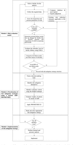
As can be seen, the framework consists of three modules: the first module is aimed at risk evaluation, the second module deals with selection of the most appropriate risk mitigation strategy, and the third module is responsible for implementation of the selected risk mitigation strategy. The steps involved in each of these three modules are described in detail as follows:
3.1. Module 1. Risk evaluation model
3.1.1. Select a facility for the analysis
There are several facilities installed on both topside and subsea equipment in the offshore oil and gas industry. In order to apply the proposed framework, the field managers must identify a critical facility for risk assessment. However, as far HPHT conditions are concerned, it is very likely that a subsea facility to be selected because of their close proximity to HPHT wells. The subsea facilities that can be considered for risk evaluation are: wellheads, seals, subsea trees, control systems, flowlines, umbilicals, manifold, subsea flying leads, jumper spool and subsea connectors.
3.1.2. Collect the required data
In order to assess the risks associated with failure of the selected facility, the risk analysts must have proper understanding of the facility’s function as well as its interaction with HPHT well fluid and the immediate environment. This means that some technical information about the chosen facility must be collected. Based on literature review performed as part of this research, a list of data required for risk analysis of oil and gas facilities operating in HPHT environments was prepared and validated with a team of experts including subsea engineers, safety professionals, regulators and inspectors. The final list of the data types and their sources is given in Table .
Table 1. A list of data types and their sources for performing risk analysis on oil and gas facilities in HPHT conditions.
3.1.3. Determine potential failure modes that may damage the facility due to elevated pressure and temperature of wells by analysing past records
Identification of possible damages to oil and gas facilities caused by elevated pressure and temperature of wells is an essential part of risk analysis studies in HPHT environments. This task can be achieved through literature review or by interviewing experts such as manufacturers, suppliers, designers, subsea operators and maintenance technicians. Typical failure modes due to HPHT conditions include: material degradation, casing collapse, gas leakages, buckling of pipelines (both lateral and upheaval buckling), sheathing of cement over the well life, extreme stresses in pipelines, excessive loading on terminals at hot ends, de-rating of the pipeline carbon steel material, increased internal corrosion and reduced efficiency of cathodic protection systems (Wray et al., Citation2009; Azouz, Citation2010; Shadravan and Amani, Citation2012; Kaculi, Citation2015). Any of these failure modes or their combination can result in severe consequences during life extension phase of operation.
3.1.4. Evaluate the criticality level of facility failures using FMEA approach
In order to account for the risks associated with failure of oil and gas facilities due to elevated pressure and temperature of well fluid, the FMEA technique is used. FMEA is a simple and straightforward tool which is commonly used for risk assessment in the oil and gas industry. Shafiee and Dinmohammadi (Citation2014) and Shafiee et al. (Citation2019b) indicated that a FMEA study should identify known and possible failure modes, analyse causes of failure modes, determine the effects of each failure mode, prioritise the failure modes based on RPN values, and provide appropriate risk mitigation strategies.
In order to implement the FMEA process, risk analyst must assign a probability of occurrence (O) rating to each failure mode of the facilities operating in HPHT environments. This can be achieved by analysing failure data using statistical tools such as Weibull analysis to estimate the likelihood of a failure. This is then followed by assigning severity (S) and detectability (D) ratings to failure modes. The O, S and D ratings are used to calculate Risk Priority Number (RPN), which is an index for ranking the highest risk for special attention. Tables – show 5-point scales for assigning O, S and D to each failure mode.
Table 2. Ratings for probability of occurrence of a failure (O) (Shafiee et al., Citation2019b).
Table 3. Ratings for severity of a failure (S) (Shafiee et al., Citation2019b).
Table 4. Ratings for detectability of a failure (D) (Shafiee et al., Citation2019b).
As shown, each scale varies from 1 to 5, where 1 represents the minimum rating and 5 represents the maximum rating. The RPN is a dimensionless parameter in FMEA which represents the criticality level of each failure mode and is calculated by: RPN = O × S × D. Since the O, S and D ratings are between 1 and 5, the RPN will range from 1 to 125. The RPN values obtained for each failure mode are then ranked in descending order and the most critical failure modes are identified.
3.1.5. Categorise the failure modes into three classes of criticality
After evaluating the criticality level of the failure modes, they are categorised into three classes: low, medium and high. The three levels of failure criticality and their corresponding actions on how to eliminate or reduce the risks are presented in Table . The criticality level of a failure mode is considered low when the RPN value is between 1 and 20, medium when the RPN value is between 21 and 45, and high when the RPN value is greater than 45.
Table 5. Three classes of failure criticality and corresponding mitigation actions.
3.2. Module 2. Prioritisation of risk mitigation strategies for critical failures using a hybrid AHP-PROMETHEE approach
At this stage of the decision-making process, the risk analyst is required to introduce measures that are capable of reducing or eliminating the high risks in order to achieve an acceptable level of criticality during life extension phase. In real-life practices, more than one risk mitigation alternative may be identified as appropriate for a particular failure mode. It is always important for stakeholders to explore wide range of risk mitigation strategies, however, they should eventually choose the best one among the alternatives.
Selection of the best risk mitigation solution for oil and gas facilities operating in HPHT conditions is a very complex and critical task. In this paper, we propose a hybrid AHP-PROMETHEE method which provides stakeholders with a useful and powerful tool for ranking the risk mitigation strategies. The steps of the proposed method are explained as below:
3.2.1. Form a decision-making team
A panel of experts is formed to decide on the most appropriate risk mitigation strategy. The decision-making process requires a multidisciplinary team composed of designers, subsea engineers, material analysts, structural engineers, health and safety professionals, practitioners from O&M department, financial analysts, etc.
3.2.2. Identify risk mitigation alternatives
The combined expertise of decision-makers will enable them to propose suitable strategies for the mitigation of risks associated with HPHT conditions. For each identified risk mitigation alternative, the experts must give technical justification on how the strategy can mitigate the risks. Any of the experts who disagree with a suggestion must also provide their technical reasons for disagreement. At the end, a final list of risk mitigation alternatives is agreed by all the experts.
3.2.3. Identify evaluation criteria using the Delphi technique
In order to prioritise the risk mitigation strategies, it is needed to define a set of evaluation criteria. These criteria can be defined based on the experience of the panel members as well as literature review. To combine information elicited from experts’ judgement and that from literature, one must use a systematic and structured approach such as the Delphi technique. This technique has the benefit of allowing anonymous experts in a particular field to exchange views on ethical issues over a series of rounds while the average estimate from the final round is considered as a group decision (Rowe and Wright, Citation2001). Therefore, the Delphi technique is used in this study to screen the evaluation criteria to ensure that only the important criteria are considered when prioritising risk mitigation strategies.
The first step in using the Delphi technique is to identify a facilitator and select a panel of experts. The next step is to develop a questionnaire (either open-ended or close-ended) which is sent to the experts panel for the first round of Delphi survey. The results of the first round are analysed and along with a second questionnaire are sent to the experts for second round Delphi survey. The iteration process continues until a consensus is reached by all the experts. The mean value, standard deviation and the content validity ratio are some of the measures used to remove or retain criteria in order to reach a consensus.
3.2.4. Estimate the weights of criteria by means of AHP
The weights reflect the degrees of importance of criteria based on their respective preference functions. AHP was developed by Prof. Thomas L. Saaty in the 1970s (Saaty, Citation1980) to address the difficulty in determining the relative importance of a set of activities in an MCDA problem. Since then it has become the most popular MCDA method. AHP incorporates judgements of intangible qualitative criteria alongside tangible quantitative criteria (Badri, Citation2001). The method helps decision-makers decompose a complex problem into a hierarchical structure with the goal (objective) at the top level followed by criteria, sub-criteria, and alternatives in the lower levels (Saaty, Citation1990; Zio, Citation1996). Selection of the most suitable alternative requires pairwise comparisons and computing an index called consistency ratio (CR) to test the consistency of the comparisons. The weight for pairwise comparison is obtained using Saaty’s 1–9 scale, as shown in Table .
Table 6. Saaty’s 1–9 scale for pairwise comparisons (Shafiee et al., Citation2019c).
The steps for AHP analysis are outlined below:
Define the evaluation criteria for the selection of most suitable risk mitigation strategy.
Design AHP questionnaire for k experts to perform pairwise comparisons using established ratio of relative importance for n decision criteria. Numerical values (i.e. weights) from each expert are used to form a matrix, Ak.
(1)
The weights of criteria are computed through the pairwise comparison matrix Ak and using the following equation:
After testing the consistency of judgement matrices for panel members, the aggregated judgement matrix, A is constructed. This matrix is given by:
The consistency ratio, Ir for each comparison matrix is calculated using Equation (5):
(5)
(5) where CI is the consistency index which is given by:
(6)
(6) where
is the maximum eigenvalue of the matrix A. The random index (RI) in Equation (5) represents the corresponding average random values for a pairwise comparison matrix. The RI values for different matrix sizes are given in Table .
Table 7. Random index (RI) values for different matrix sizes (Saaty, Citation1996).
The judgment is considered to be consistent and acceptable if CR is less than 0.1, otherwise the process must be repeated (Saaty, Citation1980).
3.2.5. Apply PROMETHEE II
The PROMETHEE technique was first developed by Brans and Vincke (Citation1985). This technique is a useful MCDA method to outrank a set of finite alternatives and then select the best alternative among the possible options. The PROMETHEE technique uses positive and negative preference flows for different alternatives, in order to produce ranking in relation to decision weights (Kabir et al., Citation2014). Several different versions of the PROMETHEE technique have been developed in literature to face complicated decision-making problems, including: PROMETHEE I (partial ranking), PROMETHEE II (complete ranking), PROMETHEE III (ranking based on intervals), PROMETHEE IV (continuous case), PROMETHEE V (PROMETHEE II and integer linear programming), PROMETHEE VI (weights of criteria are intervals) and PROMETHEE GAIA (graphical representation of PROMETHEE) (Silva et al., Citation2010). Vinodh and Girubha (Citation2011) reported that PROMETHEE II is the most popular version used to rank alternatives, as it establishes a complete ranking or pre-order of alternatives. Thus, in this study, the PRMOTHEE II is adopted. The main steps of implementing the PROMETHEE II technique are described below (Animah and Shafiee, Citation2019):
Determine the deviation based on pairwise comparisons as follows:
Evaluate the preference function. The preference function is defined as the degree of preference of alternative a over alternative b in the jth criterion:
Evaluate the global preference index. The aggregated preference index for two alternatives a and b,
Evaluate the outranking flows. The net outranking flow which is used to measure the performance of each alternative is calculated using Equation (10):
The greater values of show the strong preference of one alternative in comparison to other alternatives. The negative outranking flow for each alternative is defined by:
(11)
(11)
The net outranking flow is the difference between the positive flow
and the negative flow
, which is calculated by:
(12)
(12)
Therefore, if , then alternative a is better than alternative b.
3.2.6. GAIA plane
The GAIA (Geometrical Analysis for Interactive Aids) plane is a graphical tool which is part of the PROMETHEE software. This tool helps better understand a multi-dimensional MCDA problem by projecting it to a two-dimensional figure while losing minimum information (Nikouei et al., Citation2017). The GAIA plane is constructed by decomposing the net outranking flow by means of a principal component analysis (PCA) algorithm. The GAIA analysis is considered suitable when its quality level is equal or greater than 70% (Kabir and Sumi, Citation2014).
3.3. Module 3. Implementation of the risk mitigation strategy
The third module deals with the implementation of most suitable risk mitigation strategy during life extension phase of oil and gas facilities in HPHT environments. This task requires decision-makers to perform some analyses to ascertain the risk reduction achievable by implementing the selected mitigation strategy.
4. Case study application
The proposed framework is applied to evaluate the risks associated with failures of subsea manifold and flowlines operating in HPHT environments as well as to select the most appropriate strategy for mitigating such risks, in order to support life extension decision-making in the offshore oil and gas industry. The field selected for this study has existing production reservoirs depleted at the end of its life. However, the company has discovered new wells which could be economically explored to improve revenue if the life of the field is extended. The new wells would tie back to a 30-year old flowline with an existing manifold. The new wells have HPHT characteristics but with higher CO2 content compared to the existing wells. However, the fitness-for-purpose (FFP) assessment indicated that the existing manifold and flowlines were not designed to resist the loadings from HPHT wells; therefore extending the life of the field may expose significant risks to assets, personnel and the environment. This is because the existing flowline will suffer increased corrosion and excessive loading of hot end terminals which may lead to gas leakages. Nonetheless, asset managers could still benefit from extending the life of the field if the risks associated with failure of the manifold and flowlines due to HPHT conditions can be accurately estimated. Depending on the risk criticality levels, the most appropriate strategy is determined to reduce the risks to an acceptable level of tolerance to enable the life extension of the field.
4.1. Module 1
4.1.1. Select a facility for the analysis
The facilities selected in this study include the subsea manifold and flowlines. The manifold which is an interface between the wellhead and subsea flowlines is used to gather gas and then transport it through the subsea flowlines to a Floating Production Storage and Offloading (FPSO).
4.1.2. Collect the required data
The data required for the analysis was collected from literature and verbal interviews with experts with experience in developing HPHT wells as well as operating subsea facilities in HPHT environments. The data collected for the analysis are given in Table .
Table 8. The data collected for the case study.
4.1.3. Determine potential failure modes that may damage the facility due to elevated pressure and temperature of wells by analysing past records
Due to the paucity of information on HPHT wells in the oil and gas industry, the possible failure modes of the manifold and flowlines were identified through literature review. Then, the experts were consulted through semi-structured interviews to confirm the final list of failure modes. Initially, a total of 15 possible failure modes were identified, however, these were reduced to eight after consultation with the experts. This is because that the rejected failure modes were found not to be caused by HPHT conditions.
4.1.4. Evaluate the criticality level of facility failures using FMEA approach
The risk evaluations for the manifold and flowlines were performed using the FMEA technique and the results are shown in Table . It should be noted that the numerical probabilities were obtained based on the inputs from academic researchers with several years of experience and publications in this subject area.
Table 9. FMEA results for manifold and flowlines under HPHT conditions.
With reference to Table , five failure modes are classified as highly critical, i.e. their RPNs are greater than 45. Two failure modes of ‘extreme thermal stresses on connectors’ and ‘general mechanical failure/breakdown’ have the highest RPN value of 125. These are followed by ‘excessive loading of hot end terminals’ with the RPN value of 100, and ‘material degradation’ and ‘loss of barrier’ with the RPN value of 48. Therefore, to proceed with life extension of the field, asset managers are obliged to take the necessary measures to reduce these risk levels by selecting an appropriate risk mitigation strategy. Therefore, the second module of the proposed framework is applied.
4.2. Module 2
4.2.1. Form a decision-making team
The decision-making team consisted of a panel of five experts who were carefully selected during a meeting with stakeholders. They included two subsea engineers (DM 1 and DM 2) with several years of experience in operating and maintaining equipment in harsh conditions in the offshore oil and gas industry. DM 3 and DM 4 were from the academia, and the fifth expert DM 5 was a design engineer from a design consultancy firm.
4.2.2. Identify risk mitigation alternatives
The risk mitigation alternatives were identified through literature review (e.g. Azouz (Citation2010)) and subsequently agreed upon by all the DMs based on their expertise and experience. These alternatives are presented in Table .
Table 10. Risk mitigation strategies for manifold and flowlines under HPHT conditions.
4.2.3. Identify evaluation criteria using the Delphi technique
The questionnaire for identifying the evaluation criteria was piloted among the academic researchers with substantial experience and publications in this area of study. After a successful piloting, a total of 15 evaluation criteria were identified from both literature review and face to face interview with the panel of experts. The experts then screened the 15 criteria using the Delphi technique, in order to select the most appropriate criteria for further analysis. The Delphi process was terminated after evaluating the results of the second round questionnaire, since there was no significant difference between the outcome of first round and second round. The consensus measurements for the five experts were evaluated after the second round of the Delphi survey. Evaluation criteria with mean values less than 50% were discarded. The final evaluation criteria considered for the study are explained below:
4.2.3.1. C1: Economic criteria
The implementation of risk mitigation strategies has different cost implications for asset managers during life extension phase of operation. In this study, the economic criteria are considered in terms of capital investment, cost of annual O&M, cost of training personnel and cost of equipment repair. The three factors C11, C12 and C13 are measured in monetary unit and a smaller value is preferred to a higher value. The factor C14is measured using an ordinal scale with five levels, including: very low, low, moderate, high and very high, and a lower impact is preferred to a higher impact.
4.2.3.1.1. C11: Capital investment. This factor corresponds to the capital expenditure involved in implementing a risk mitigation strategy. It consists of the cost of purchasing new equipment, cost of installation, and cost of purchasing computers as well as advance software for monitoring, if required.
4.2.3.1.2. C12: Cost of annual operation and maintenance (O&M). This factor refers to the cost of O&M, including cost of engineering/technician service and cost of materials for ensuring that risk mitigation strategy continues to perform its intended function throughout the extended period of operation.
4.2.3.1.3. C13: Cost of training. This factor represents all the costs required to train personnel in order to acquire the skills and knowledge needed for implementing the risk mitigation strategies.
4.2.3.1.4. C14: Cost of equipment repair. Under HPHT conditions, it is likely that the HPHT wells cause damage to facilities such as flowlines, manifolds and other topside process facilities which may result in additional cost to asset owners. Therefore, this criterion refers to how a risk mitigation strategy can reduce the repair cost of equipment damage due to HPHT effects.
4.2.3.2. C2: Safety criteria
In the offshore oil and gas industry, health and safety remain a top priority for facilities operating in HPHT environments. It is, therefore, one of the key factors that must be taken into account when selecting a risk mitigation strategy for subsea facilities that operate in harsh conditions. The factors considered include the safety impacts on personnel, equipment and the environment. Each of these factors is measured using an ordinal scale with five levels, including: very low, low, moderate, high and very high.
4.2.3.2.1. C21: Safety of personnel. The failure of subsea facilities operating in HPHT environments may lead to serious injuries or death to personnel who work on the platform. Under such conditions, the risk mitigation strategy must be implemented regardless of cost.
4.2.3.2.2. C22: Safety of equipment. The failure of subsea facilities which are responsible for handling HPHT well fluids can put the entire subsea and topside process facilities at risk and make them unsafe. During life extension phase of operation, a greater attention must be paid to high risk facilities. Therefore, a suitable risk mitigation strategy should be selected to ensure that the risks associated with failure of subsea facilities during life extension phase of operation is reduced to tolerable levels.
4.2.3.2.3. C23: Safety of the environment. The failure of subsea facilities operating under HPHT conditions may lead to serious environmental consequences such as pollution. An appropriate risk mitigation strategy can potentially reduce the environmental risks associated with failure of subsea facilities in HPHT environments.
4.2.3.3. C3: Added value
The added value refers to the benefits that can be gained from implementing a risk mitigation strategy. These benefits are expressed in terms of increased production and improved maintenance. Each of these factors is measured using an ordinal scale with five levels, including: very low, low, moderate, high and very high.
4.2.3.3.1. C31: Increased production. The failure of subsea facilities operating under HPHT conditions may lead to reduction in production capacity. Selection of an appropriate risk mitigation strategy can reduce the number of failures in subsea facilities due to elevated pressure and temperature of well fluid, and this can potentially increase the production.
4.2.3.3.2. C32: Improved maintenance. The type of damage and the significance of its impact can determine how fast a failed unit can be restored to normal operating condition by operators (Markeset et al., Citation2009). Selecting an appropriate risk mitigation strategy can potentially reduce the level of damage to subsea systems which may be caused by HPHT conditions, thereby reducing the maintenance lead time and effort.
4.2.3.4 C4: Acceptability. This criterion represents the acceptability of a risk mitigation strategy by asset owners as well as regulators. Each of these factors is measured using an ordinal scale with five levels, including: very low, low, moderate, high and very high.
4.2.3.4.1. C41: Acceptance by asset owners. A risk mitigation strategy requires the support and approval of asset owners including companies, operators and investors.
4.2.3.4.2. C42: Acceptance by regulators. The successful implementation of a risk mitigation strategy in the offshore oil and gas industry requires a broad acceptance and approval by regulatory agencies.
4.2.4. Estimate weights of criteria by means of AHP
The local weights of the main criteria and sub-criteria were calculated using Saaty’s 1–9 scale given in Table and Equations (1)–(3). To obtain the local weights, the panel of experts were asked to make pairwise comparisons for the main criteria and sub-criteria. The global weights for the sub-criteria were then calculated by aggregating the local weights of main criteria and sub-criteria. The simple average or geometric mean of individual experts’ judgements can be used to obtain the results, however, in this study a consensus was reached by the panel of experts during evaluation. The pairwise comparison matrix for the main criteria with respect to the goal is shown in Table .
Table 11. Pairwise comparison matrix for the main criteria with respect to the goal.
The consistency ratio of the pairwise comparison matrix shown in Table is calculated 0.07. This implies that the experts’ opinions are consistent and satisfactory. Similarly, the pairwise comparison matrix for the sub-criteria with respect to the criteria are constructed. For instance, Table shows the pairwise comparison matrix for the sub-criteria C11, C12, C13 and C14 with respect to C1.
Table 12. Pairwise comparison matrix for four sub-criteria with respect to ‘economics’ criterion.
The local weights of the main criteria and the local and global weights of the sub-criteria are shown in Table .
Table 13. Local and global weights of the criteria.
After aggregating the values, the importance weights of the criteria were obtained as W = [0.6058, 0.1346, 0.1442, 0.1154]. As shown in Table , the experts considered C1 as the most determinant factor in selecting an appropriate risk mitigation strategy for subsea facilities in HPHT conditions during life extension phase of operation.
4.2.5. Apply PROMETHEE II
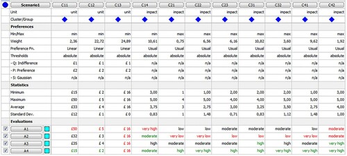
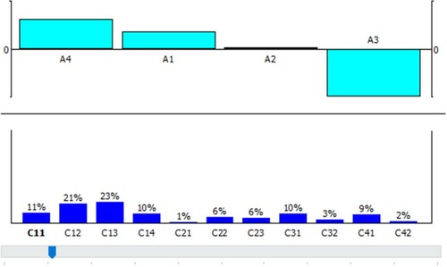
The most appropriate risk mitigation strategy is selected with respect to the criteria using Visual PROMETHEE software (http://www.promethee-gaia.net). In this study, a linear function is selected as the preference function for the first three quantitative criteria, whereas the rest of nine qualitative criteria apply the usual criterion as the preference function. This is because the linear preference function is more suitable for quantitative evaluation criteria but the usual preference function is more appropriate for qualitative criteria (Turcksin et al., Citation2011). Figure presents the risk mitigation strategy selection process with the use of Visual PROMETHEE software.
Figure 3. Risk mitigation strategy selection using Visual PROMETHEE software.
The PROMETHEE II was applied to obtain the ranking of risk mitigation alternatives. The positive, negative and net outranking flows for risk mitigation alternatives are given in Table . The risk mitigation alternatives are ranked in descending order according to the net outranking flow.
Table 14. Positive, negative and net outranking flows for risk mitigation alternatives.
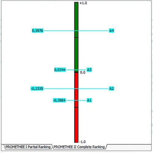
The alternative with the highest value of net outranking flow is considered as the most preferred solution. Therefore, A4 with net outranking flow of 0.5976 is selected as the most appropriate risk mitigation strategy. The next suitable choice is A3, followed by A2 and the last choice is A1. The PROMETHEE complete ranking is illustrated in Figure .
Figure 4. The PROMETHEE II complete ranking.
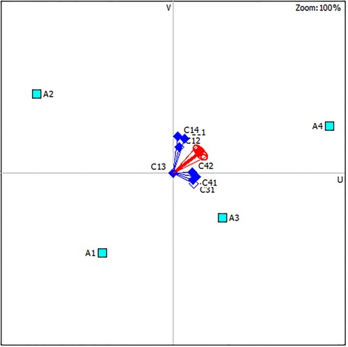
The results of the PROMETHEE II analysis using the GAIA plane is depicted in Figure . Six dimensional spaces of criteria are projected on a two-dimensional plane using the PCA method. The quality level for visualisation is 96.7%, indicating that very little information was lost by the projection and this guarantees the validity of our results.
Figure 5. The results of the PROMETHEE II using the GAIA plane.
In MCDA, any changes in the weights of the evaluation criteria may significantly impact the priority rankings. Thus, a sensitivity analysis is performed to test the robustness of the proposed decision-making framework. The weights of the evaluation criteria are changed using the walking weights feature provided in the Visual PROMETHEE software. In consultation with the experts, we obtained the modified weights for the sensitivity analysis. The results of the sensitivity analysis after modifying the weights of the evaluation criteria are shown in Figure .
Figure 6. Results of the sensitivity analysis after modifying the weights of criteria.
As shown in Figure , the final rankings of the risk mitigation strategies changed with modifying the weights of the evaluation criteria. This means that the criteria weights assigned by decision makers can influence the results of the proposed framework.
4.3. Module 3
The objective of selecting A4 as the most appropriate risk mitigation strategy is to reduce the level of risks associated with failure of the manifold and flowlines due to HPHT conditions during the extended life of operation. The risks are minimised by controlling the high temperature of well fluid to normal operational temperature using the subsea cooling spool. This means that well product temperature must be controlled sensitively to achieve the desired operational temperature, in order to prevent hydrate formation which may lead to safety hazards to transportation systems, economic risks and other flow assurance challenges. By applying the heat transfer models, Bai et al. (Citation2009) found out that the major factor affecting the desired temperature output is the spool length. The results of the thermal analysis indicated that to achieve the normal operational temperature of 120°C, a spool length of 106 m is required.
5. Conclusions and future work
In this paper, a new framework integrating FMEA and hybrid AHP-PROMETHEE methods was presented to evaluate and prioritise the risk mitigation strategies during life extension phase of operation for oil and gas facilities in HPHT environments. The proposed framework can serve as a powerful risk management tool for asset managers, risk analyst, regulators and policy makers in the oil and gas industry. The framework consists of three main modules, including: (i) risk evaluation module – aimed at evaluating the risks associated with failure of offshore oil and gas facilities under HPHT conditions; (ii) risk mitigation selection module – aimed at choosing the most effective risk mitigation strategy to minimise the economic, environmental and safety consequences of asset failure; and (iii) risk strategy implementation module – used for thermal and pressure analysis of the selected risk mitigation strategy for subsequent implementation.
The framework was applied to subsea oil and gas manifold and flowlines that are used to collect and transport methane gas from HPHT wells. The data required for testing the framework was collected from literature review, company’s internal documents, as well as a team of experts with experience in operating subsea facilities in harsh conditions. The FMEA technique was used to identify failure modes of the subsea manifold and flowlines caused by elevated pressure and temperature of well product, while the hybrid AHP-PROMETHEE method was used to select the most appropriate risk mitigation strategy. The results of the risk evaluation showed that five failure modes (out of the eight identified failure modes) were classified as highly critical. On the other hand, the subsea cooling spool was selected as the most appropriate risk mitigation strategy. In order to minimise the risk of high temperature, the thermal analysis indicated that a spool length of 106 m is suitable for reducing the temperature of well fluid from 156°C to normal operational temperature of 120°C.
One of the main contributions of the proposed framework is that it can provide decision makers in the offshore oil and gas industry with a model which considers both subjective judgements (qualitative) and objective (quantitative) evaluation measures for risk management. However, there is wide scope for future research work in relation to risk management decision-making of oil and gas facilities in HPHT environments. Some suggested future work directions are as follows:
Evaluation of risks using FMEA can result in uncertainties in decision making due to incomplete information or subjective nature of expert inputs for O, S and D scales. Thus, the RPN of the conventional FMEA may not always provide consistent evaluation and prioritisation of risks associated with subsea facilities operating in HPHT conditions. Hence, for future research work, some risk assessment methodologies such as hazard and operability study (HAZOP) and layer of protection analysis (LOPA) can be combined with modern dynamic risk assessment methodologies such as Monte Carlo, Bayesian Network, Markov chain model and Petri Network (PN) for risk assessment of subsea critical facilities.
In this study, we proposed a hybrid AHP-PROMTHEE approach to prioritise the risk mitigation strategies for oil and gas facilities in HPHT environments. Future research work must consider combining MCDA methods with fuzzy logic inference systems for selecting the most suitable risk mitigation strategy;
The results of this study can be compared with other MCDA methods such as TOPSIS, ELECTRE and VIKOR.
Subsea cooling spool is a relatively new technology in the offshore oil and gas industry. The technology is now evolving and thus has received very limited attention in literature and field application. Future research work can focus on design analysis of subsea cooling spool and the application of MCDA methods to select the most suitable cooling spool configuration for use in HPHT environments.
Disclosure statement
No potential conflict of interest was reported by the author(s).
References
- Animah I, Shafiee M. 2018. Condition assessment, remaining useful life prediction and life extension decision making for offshore oil and gas assets. J Loss Prev Process Ind. 53:17–28. doi: https://doi.org/10.1016/j.jlp.2017.04.030
- Animah I, Shafiee M. 2019. Maintenance strategy selection for critical shipboard machinery systems using a hybrid AHP-PROMETHEE and cost benefit analysis: a case study. Journal of Marine Engineering & Technology. doi:https://doi.org/10.1080/20464177.2019.1572705.
- Animah I, Shafiee M. 2020. Application of risk analysis in the liquefied natural gas (LNG) sector: An overview. J Loss Prev Process Ind. 63, 103980. doi: https://doi.org/10.1016/j.jlp.2019.103980
- Animah I, Shafiee M, Simms N, Erkoyuncu JA, Maiti J. 2018. Selection of the most suitable life extension strategy for ageing offshore assets using a life-cycle cost-benefit analysis approach. J Qual Maint Eng. 24(3):311–330. doi: https://doi.org/10.1108/JQME-09-2016-0041
- API 17TR8. 2018. High-pressure high-temperature design guidelines. 2nd ed. Washington, D.C: American Petroleum Institute (API). 110 pages. Available at: https://global.ihs.com.
- API TR 1PER15K-1. 2013. Protocol for verification and validation of high-pressure high-temperature equipment. American Petroleum Institute (API). 98 pages.
- Azouz AM. 2010. Innovative subsea cooling reduces numerous failure risks in subsea pipelines. In: International Petroleum Exhibition and Conference, Abu Dhabi, UAE, pp. 1–5.
- Badri MA. 2001. A combined AHP-GP model for quality control systems. Int J Prod Econ. 72(1):27–40. doi: https://doi.org/10.1016/S0925-5273(00)00077-3
- Bai Q, Qi X, Brunner MS. 2009. Global buckle control with dual sleepers in HP/HT pipelines. In: Offshore Technology Conference, 4–7 May, Houston, Texas, pp. 1–12.
- Barrilleaux M, Deegan J, Waligura J, Walker G. 2001. Dynamically positioned completion operations risk analysis. In: Offshore Technology Conference, 30 April–3 May, Houston, Texas, pp. 1–10.
- Behzadian M, Kazemzadeh RB, Albadvi A, Aghdasi M. 2010. PROMETHEE: A comprehensive literature review on methodologies and applications. Eur J Oper Res. 200(1):198–215. doi: https://doi.org/10.1016/j.ejor.2009.01.021
- Brans J-P, Vincke P. 1985. Note–A preference ranking organisation method: (The PROMETHEE method for multiple criteria decision-making). Manage Sci. 31(6):647–656. doi: https://doi.org/10.1287/mnsc.31.6.647
- Bucelli M, Paltrinieri N, Landucci G. 2018. Integrated risk assessment for oil and gas installations in sensitive areas. Ocean Eng. 150:377–390. doi: https://doi.org/10.1016/j.oceaneng.2017.12.035
- Cai B, Liu Y, Liu Z, Tian X, Zhang Y, Ji R. 2013. Application of Bayesian networks in quantitative risk assessment of subsea blowout preventer operations. Risk Anal. 33(7):1293–1311. doi: https://doi.org/10.1111/j.1539-6924.2012.01918.x
- Fenton C, Jayson D, Gillies M, Parkin A. 2002. Integrated geohazards evaluation and risk assessment for subsea facilities. In: Offshore Technology Conference, 6–9 May, Houston, Texas. pp. 1–7.
- Graham GM, Collins IR, Johnson TL. 2005. Technical and economic analysis of the scale risks and uncertainties for subsea deepwater field developments. In: SPE International Symposium on Oilfield Scale, 11–12 May, Aberdeen, United Kingdom, pp. 1–16.
- Hasle JR, Urban K, Ole H. 2009. Decision on oil and gas exploration in an Arctic area: case study from the Norwegian Barents Sea. Saf Sci. 47(6):832–842. doi: https://doi.org/10.1016/j.ssci.2008.10.019
- Health and Safety Executive (HSE). 2005. High pressure, high temperature developments in the United Kingdom Continental Shelf. Research Report 409, Prepared by Highoose Limited, Available at: http://www.hse.gov.uk/research/rrpdf/rr409.pdf.
- Helmer CM, Churcher AC, Mclvor GR, Shields RG. 1994. Arctic offshore development: managing the risk. In: Offshore Technology Conference, 2–5 May, Houston, Texas. pp. 1–12.
- Henriksson A, Wilhelmsen A, Karlsen T. 2004. Pipelines in harsh environment. In: Offshore Technology Conference, 3–6 May, Houston, Texas. pp. 1–11.
- Hoiset S, Fossan I, Kaasa O. 2008. Managing explosion risk in arctic areas. In: SPE International Conference on Health, Safety, and Environment in Oil and Gas Exploration and Production, 15–17 April, Nice, France. pp. 1–14.
- Kabir G, Sadiq R, Tesfamariam S. 2014. A review of multi-criteria decision-making methods for infrastructure management. Struct Infrastruct Eng. 10(9):1176–1210. doi: https://doi.org/10.1080/15732479.2013.795978
- Kabir G, Sumi RS. 2014. Power substation location selection using fuzzy analytic hierarchy process and PROMETHEE: a case study from Bangladesh. Energy. 72:717–730. doi: https://doi.org/10.1016/j.energy.2014.05.098
- Kaculi J. 2015. Next generation HPHT subsea wellhead systems design challenges and opportunities. In: Offshore Technology Conference, 4–7 May, Houston, Texas, USA. pp. 1–13.
- Kornishin K, Efimov YO. 2011. Risks management in Russian offshore geotechnical prospecting (Russian). In: SPE Arctic and Extreme Environments Conference and Exhibition, 18–20 October, Moscow, Russia. pp. 1–5.
- Lage A, Jacinto C, Martins F, Vanni G, Santos O, Moreiras J. 2006. Blowout contingency and risk-reduction measures for high-rate subsea gas wells in Mexilhao. In: IADC/SPE Drilling Conference, 21–23 February, Miami, Florida, USA. pp. 1–13.
- Li, C. and Liu, Z.W. (2014). The practice of Shenzhen-Hong Kong subsea gas pipeline risk analysis. In: The Eleventh ISOPE Pacific/Asia Offshore Mechanics Symposium, 12–14 October, Shanghai, China, pp. 90–95.
- Marhavilas PK, Koulouriotis D, Gemeni V. 2011. Risk analysis and assessment methodologies in the work sites: on a review, classification and comparative study of the scientific literature of the period 2000-2009. J Loss Prev Process Ind. 24:477–523. doi: https://doi.org/10.1016/j.jlp.2011.03.004
- Markeset T, Moreno-Trejo J, Kumar R. 2009. Maintenance of subsea petroleum production systems: a case study. J Qual Maint Eng. 19(2):128–143. doi: https://doi.org/10.1108/13552511311315940
- Masi S, Molaschi C, Zausa F, Michelez J. 2011. Managing circulation losses in a harsh drilling environment: conventional solution vs. CHCD through a risk assessment. SPE Drilling & Completion. 26(2):1–10. doi: https://doi.org/10.2118/128225-PA
- Morgan V, Phillips RD, Randell C, Freeman R. 2008. Mitigation of ice risk to subsea infrastructure. In: Offshore Technology Conference, 5–8 May, Houston, Texas, USA. pp. 1–9.
- Nikouei MA, Oroujzadeh M, Mehdipour-Ataei S. 2017. The PROMETHEE multiple criteria decision making analysis for selecting the best membrane prepared from sulfonated poly(ether ketone)s and poly(ether sulfone)s for proton exchange membrane fuel cell. Energy. 119:77–85. doi: https://doi.org/10.1016/j.energy.2016.12.052
- NORSOK. 2010. Standard Z-013, Risk and Emergency Preparedness Analysis, Edition 3, Lysaker, Norway. Available at: https://standards.globalspec.com/std/9966208/z-013.
- Payne M. 2016. High-pressure/high-temperature challenges. Journal of Petroleum Technology. 64:1.
- Pires TS, Morais CPM, Freitas RDA, Monteiro ALTO. 2016. Discussion on the life extension of offshore production facilities. In: Rio Oil & Gas Expo and Conference, 24–27 October, Rio de Janeiro, Brazil. pp. 1–10.
- Rowe G, Wright G. 2001. Expert opinions in forecasting: the role of the Delphi technique. In: Armstrong J.S., editor. Principles of forecasting. New York: Springer; p. 125–144.
- Saaty TL. 1980. The analytical hierarchy process. New York: McGraw Hill.
- Saaty TL. 1990. How to make a decision: The analytic hierarchy process. Eur J Oper Res. 48:9–26. doi: https://doi.org/10.1016/0377-2217(90)90057-I
- Saaty TL. 1996. Decision making with dependence and feedback. Pittsburgh: RWS publications.
- Sarwar A, Khan F, Abimbola M, James L. 2018. Resilience analysis of a remote offshore oil and gas facility for a potential hydrocarbon release. Risk Anal. 38(8):1601–1617. doi: https://doi.org/10.1111/risa.12974
- Shadravan A, Amani M. 2012. HPHT 101 - what petroleum engineers and geoscientists should know about high pressure high temperature wells environment. Energy Science and Technology. 4(2):36–60.
- Shafiee M. 2015. A fuzzy analytic network process model to mitigate the risks associated with offshore wind farms. Expert Syst Appl. 42:2143–2152. doi: https://doi.org/10.1016/j.eswa.2014.10.019
- Shafiee M, Animah I. 2017. Life extension decision making of safety critical systems: an overview. J Loss Prev Process Ind. 47:174–188. doi: https://doi.org/10.1016/j.jlp.2017.03.008
- Shafiee M, Animah I, Alkali B, Baglee D. 2019a. Decision support methods and applications in the upstream oil and gas sector. Journal of Petroleum Science and Engineering. 173:1173–1186. doi: https://doi.org/10.1016/j.petrol.2018.10.050
- Shafiee M, Animah I, Simms N. 2016. Development of a techno-economic framework for life extension decision making of safety critical installations. J Loss Prev Process Ind. 44:299–310. doi: https://doi.org/10.1016/j.jlp.2016.09.013
- Shafiee M, Dinmohammadi F. 2014. An FMEA-based risk assessment approach for wind turbine systems: A comparative study of onshore and offshore. Energies. 7(2):619–642. doi: https://doi.org/10.3390/en7020619
- Shafiee M, Enjema E, Kolios A. 2019b. An integrated FTA-FMEA model for risk analysis of engineering systems: a case study of subsea blowout preventers. Applied Sciences. 9(6):1192. doi: https://doi.org/10.3390/app9061192
- Shafiee M, Labib A, Maiti J, Starr A. 2019c. Maintenance strategy selection for multi-component systems using a combined analytic network process and cost-risk criticality model. Proceedings of the Institution of Mechanical Engineers, Part O: Journal of Risk and Reliability. 233(2):89–104.
- Silva VBS, Morais DC, Almeida AT. 2010. A multicriteria group decision model to support watershed committees in Brazil. Water Resour Manage. 24:4075–4091. doi: https://doi.org/10.1007/s11269-010-9648-2
- Smithson T. 2016. HPHT wells. Schlumberger, Available at: http://oilproduction.net/files/HP-HT-Schlumberger.pdf Accessed on 17 July 2019.
- Toldo B, Shuttleworth A, Zabelina P. 2016. Sub-surface safety valve (SSSV) erosion assessment in HPHT gas field - a case study. In: Offshore Technology Conference Asia, 22–25 March, Kuala Lumpur, Malaysia. pp. 1–11.
- Tom J, Draper S, White D, O’Neill M. 2016. Risk-based assessment of scour around subsea infrastructure. In: Offshore Technology Conference, 2–5 May, Houston, Texas, USA. pp. 1–20.
- Turcksin L, Bernardini A, Macharis C. 2011. A combined AHP-PROMETHEE approach for selecting the most appropriate policy scenario to stimulate a clean vehicle fleet. Procedia - Social and Behavioral Sciences. 20:954–965. doi: https://doi.org/10.1016/j.sbspro.2011.08.104
- Villa V, Paltrinieri N, Khan F, Cozzani V. 2016. Towards dynamic risk analysis: a review of the risk assessment approach and its limitations in the chemical process industry. Saf Sci. 89:77–93. doi: https://doi.org/10.1016/j.ssci.2016.06.002
- Vinodh S, Girubha RJ. 2011. PROMETHEE based sustainable concept selection. Appl Math Model. 36(11):5301–5308. doi: https://doi.org/10.1016/j.apm.2011.12.030
- Ward EG, Gilbert RB, Jaber J, Wolford AJ. 2001. Deepwater production system risks. In: The Eleventh International Offshore and Polar Engineering Conference, 17–22 June, Stavanger, Norway. pp. 654–659.
- Weber BJ, Mudan KS. 1992. Arctic pipeline risk assessments. In: The Second International Offshore and Polar Engineering Conference, 14–19 June, San Francisco, California, USA, pp. 15–20.
- Wray BL, Bedford DR, Leotaud L, Hunter WJ. 2009. The application of high-density elastic cements to solve HP/HT challenges in South Texas: The success story. In: SPE Annual Technical Conference and Exhibition, 4–7 October, New Orleans, Louisiana. pp. 1–17.
- Yusoff NH, Yusof MR. 2009. Managing HSE risk in harsh environment. In: Asia Pacific Health, Safety, Security and Environment Conference, 4–6 August, Jakarta, Indonesia. pp. 1–6.
- Zio E. 1996. On the use of the analytic hierarchy process in the aggregation of expert judgments. Reliability Engineering and System Safety. 53:127–138. doi: https://doi.org/10.1016/0951-8320(96)00060-9