
 ?Mathematical formulae have been encoded as MathML and are displayed in this HTML version using MathJax in order to improve their display. Uncheck the box to turn MathJax off. This feature requires Javascript. Click on a formula to zoom.
Abstract
The propulsion demands of high-speed naval vessels often rely on gas turbines, producing significant amount of power achieving thus high performance requirements. Gas turbines can be used either to provide purely mechanical propulsion, or alternatively to generate electricity, which is subsequently used by electric drives to propel the ship. However, the thermal efficiencies of gas turbines are lower than those of Diesel engines of similar power. In the context of improving the performance of existing marine gas turbines, it is proposed to enhance engine’s performance by integrating a pressure wave supercharger (or wave rotor), while keeping the basic components of the baseline engine unchanged. This article is an application of a method developed by the author for marine gas turbines with and without recuperator, [Fatsis 2019]. It is found that important benefits are obtained for the topped engines in comparison to the self-standing baseline engines. The wave rotor integration is more appropriate for engines with low compression ratios and high turbine inlet temperatures. Application of wave rotor technology to recuperated marine gas turbines shows efficiency gain exceeding 19% for all the compression ratio and turbine inlet temperatures examined.
Abbreviations: COGAS, Combined gas turbine and steam turbine; COGES, Combined gas turbine electric and steam; GTE, Gas turbine engines
Nomenclature
| FA | = | Fuel to air ratio |
| FCV | = | Fuel calorific value, MJ/kg |
| Cpa | = | Specific heat of air, J/kg K |
| Cpg | = | Specific heat of exhaust gases, J/kg K |
| = | Mass flow rate, kg/s | |
| n | = | efficiency |
| P | = | Pressure, Pa |
| PR | = | Wave rotor pressure ratio |
| rc | = | Compressor pressure ratio |
| sfc | = | Specific fuel consumption, kg/kJ |
| T | = | Temperature, K |
| TIT | = | Turbine inlet temperature, K |
| = | Power, W | |
| ws | = | Specific power, MJ/kg |
Greek Symbols
| γ | = | Ideal gas constant |
| ΔP | = | Pressure losses, Pa |
Subscripts
| 0 | = | Stagnation conditions |
| 1 | = | Intake |
| 2 | = | Compressor inlet |
| 3 | = | Compressor exit |
| 4 | = | Wave rotor inlet |
| 5 | = | Mixer |
| 6 | = | Compressor turbine inlet |
| 7 | = | Compressor turbine exit |
| 8 | = | Power turbine exit |
| 9 | = | Exhaust |
| α | = | Ambient |
| C | = | Compression processes inside the wave rotor |
| E | = | Expansion processes inside the wave rotor |
| f | = | Fuel |
| g | = | Exhaust gases |
| cc | = | Combustion chamber |
| isc | = | Isentropic compressor |
| ist | = | Isentropic turbine |
| HE | = | Heat exchanger |
Introduction
During the last 40 years most Navies have begun to utilise aero-derivative gas turbine engines as prime movers for surface combatants due to enhanced performances that could not be attained with diesel engines, Brady (Citation1988). Although the naval community had attempted the use of this type of engines for ship propulsion earlier, it was only after a successful commercial campaign during the 70s that gas turbines were used for naval propulsion systems. Development in gas turbine technology during the last years made possible reduced manning, maintenance and weight, short warm-up times, ease of control, low NOX and negligible SOX emissions due to higher grades of fuel and therefore reduced cost, Kayadelen and Üst (Citation2013). Simple gas turbine cycles attain levels of thermal efficiency of approximately 37%. When compared to diesel engines, gas turbines require less space for the main engine and the auxiliaries; create reduced vibrations and have faster reaction to variations of loading, Alvarez et al. (Citation2015). The main disadvantages of gas turbines are related to high fuel consumption which combined to the high price of the fuel for aero-derivative gas turbines, makes their operation costly. Additionally, the efficiency of gas turbines drops as the ambient temperature rises, and thermal efficiencies of gas turbines are lower than those of diesel engines of similar power. Therefore several methods have been adopted to improve the efficiency of gas turbines for naval use (RAENG Citation2013). The most popular of those applied in naval gas turbine engines (GTEs) is the ICR (Intercooled Recuperated) cycle where a recuperator (or regenerator) is added after the low-pressure compressor, prior to the combustion chamber of the intercooled cycle to recover waste exhaust heat and heat up the compressed air.
A feasibility study of intercooling and regenerating the marine RR-Spey gas turbine engine was conducted by Thomson et al. (Citation1987). It was demonstrated that the RR-Spey SM1A engine was modified by adding intercooler and regenerator attaining a gain in fuel consumption of more than 20%. The ICR engine based on the RB211 aero-engine is projected to save up to 30% annual fuel savings according to Cristall and Parker (Citation1993). Shepard et al. (Citation1994) presented in a comprehensive way the requirements, technical specifications and project implementation details. English (Citation2003) concluded that the WR-21 engine offers significant benefits in terms of efficiency, reliability, reduced maintenance cost, as well as improved naval characteristics for existing and new generation Frigates and Destroyers. Part-load performance of two-shaft gas turbines can be improved by introducing variable guide vanes (VGV) as suggested by Haglind (Citation2010).
An alternative to overcome the part-load performance is to install and configure the gas turbine to operate in combination with other propulsion prime movers such as the diesel engine either as ‘Combined Diesel and Gas turbine’ (CODAG) or as ‘Combined Diesel or Gas Turbine’ (CODOG) configuration in which boost power for top speed operations is to be provided by the bigger engine, while low-speed fuel economy at low power settings is to be provided by the smaller one whenever necessary as Parker et al. (Citation1998) recommend.
Gas turbine emissions satisfy the MARPOL Tier III requirements (IMO Citation2008). NOx and SOx emissions of gas turbine engines are less than Internal Combustion Engines equipped with SCR with urea-injection and closed-loop scrubbers, offering a significant reduction in the main machinery space, weight and volume (Armellini et al. Citation2015).
In cruise ships or cargo vessels, the choice of LNG as fuel for the gas turbines reduces substantially the reduction of CO2 emissions. The steady state and controlled combustion in gas turbines allow significant reduction in NOx emissions, easily matching nitrogen regulations for current marine engines, (Barsi et al. Citation2019).
Haglind (Citation2008a, Citation2008b) underlines that the aim of combining different propulsion configurations for large ships is the optimisation of system design in order to minimise fuel consumption and maximise operating flexibility and reliability. The ‘Combined Gas and Steam Turbine’ (COGAS) where the shafts of the turbines drive directly the propeller constitutes one type of configuration, whereas the ‘Combined Gas Turbine and Steam Turbine integrated Electric Generator’ (COGES) is another possible configuration.
Barsi et al. (Citation2020) showed that small gas-steam combined plants can be used in various naval applications, both as a prime mover, or combined with other engines or in modular configurations for application on larger vessels.
At full load the COGAS configuration offers higher efficiency as the transmission efficiency is higher. With a COGES configuration, it is easier to achieve rational part-load performance, because one or several power units can be shut off as the power is reduced while the remaining power units are operated at their high efficient power condition, (Cristall and Parker Citation1993).
A novel method for efficiency improvement and power increment, originally proposed for aeronautical applications, is the integration of a pressure wave exchanger or wave rotor to marine gas turbines. A wave rotor consists of a purely cylindrical rotor inside a casing. The rotor is composed of two coaxial cylinders. Circumferentially equidistant axial straight thin blades are formed between these cylinders. Two stationary endwall plates with perforated circumferential openings are mounted at the rotor extremities, allowing only partial inflow and outflow through the rotor blade channels, as described by Weber (Citation1995) and Povinelli et al. (Citation2000). Depending on the number of openings (or ports), wave rotors can be classified as three-port, four-port or five-port configurations. In Figure , one can see the four-port wave rotor assembly, which is the configuration best suited as a gas turbine topping device, Wilson and Paxson (Citation1993).
Figure 1. Four-port wave rotor schematic configuration.
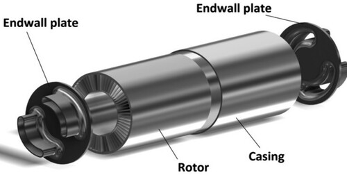
The rotor is connected via a ducting system to the compressor, turbine and combustion chamber of the baseline engine. Unlike conventional turbomachinery components, the principle of operation of wave rotors is based on propagation of unsteady pressure waves inside the various rotor channels. These moving pressure waves are formed inside the wave rotor channels when a high enthalpy gas stream (e.g. hot combustion gas) is coming in contact for a short time –so that mixing is avoided- with low enthalpy gas (e.g. compressed air) being inside the rotor. According to the basic theory of gas dynamics described by Weber (Citation1995) and verified analytically and numerically by Iancu and Müller (Citation2005), the propagation of a compression wave inside each of the rotor channels results in the formation of an expansion wave and its propagation at the opposite direction. The contact discontinuity between the high and the low enthalpy gas streams guarantees that no mixing between the two streams will occur. When a wave rotor is integrated into a gas turbine, extra compression in the air flow is achieved by means of compression waves formed inside the wave rotor channels when hot exhaust gases coming out of the combustion chamber come in contact with air from the compressor. Simultaneously expansion is achieved when expansion waves are directed at the outflow port towards the turbine. An efficient design of wave rotors is attained when the pressure waves inside the rotor result in uniform and steady flows at the outflow ports, so that the air flow towards the combustion chamber and the gas flow towards the turbine are uniform. For the case of the four-port through flow wave rotor, the rotor blades are self-cooled because hot gas and compressed air are traversing the rotor, so no extra cooling is needed. Feasibility studies of integrating a wave rotor to aircraft gas turbines showed the reduction of the specific fuel consumption and an increase of the specific thrust delivered by the engine, as stated by Jones and Welch (Citation1996). A recent publication by Fatsis (Citation2019) explored the possibility of integrating a four-port wave rotor also to industrial gas turbines. The wave rotor constant volume combustor utilises unsteady pressure waves and controlled burning to provide pressure increase during combustion, unlike the conventional chambers of gas turbine engines (Elharis et al. Citation2010). Akbari and Nalim (Citation2009) explore the benefits as well as the challenges of this concept. Complex phenomena such as unsteady combustion and flame–pressure wave interactions have not yet studied adequately and require further research effort to be fully understood.
This article is an original study on wave rotor technology applied to marine gas turbines used as prime mover for naval propulsion. It is applying the thermodynamics model developed by Fatsis (Citation2019) to marine gas turbines. Performance assessment is accomplished for two-shaft marine gas turbines with and without recuperator at design point conditions. The most important parameters of the wave rotor topped engines are identified and their variations around standard values listed in the literature indicate the effect on engine’s performance. It is concluded that the integration of wave rotor in a marine gas turbine improves the thermal efficiency of the engine and at the same time increases its specific power. The improvement is more remarkable for engines operating with low compressor pressure ratios and high turbine inlet temperatures, for the range of compressor pressure ratios examined.
Gas turbine thermodynamic calculations
Input data for two-shaft gas turbines
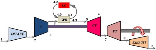
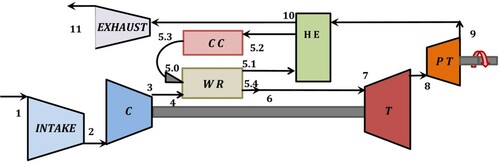
The procedure of the thermodynamic calculations of two-shaft gas turbine cycles with the integration of a four-port wave rotor is described in detail by Fatsis (Citation2018). It is based on standard thermodynamic analysis of gas turbines, as presented by Horlock (Citation2003) and by Razak (Citation2007), supplemented by modelling the processes inside the wave rotor. Figure illustrates the configurations for the wave rotor-topped two-shaft gas turbines used in this article.
Figure 2. Two-shaft gas turbine configuration, C: compressor, T: turbine, CC: combustion chamber, WR: wave rotor, CT: compressor turbine, PT: power turbine.
Two-shaft gas turbines are well-suited to marine applications because their operation covers a wide range, behaving almost as a constant power machine (Stapersma and Woud Citation2005). Various numerical models are available in the literature for the steady state, as well as for the transient simulation of gas turbines, as the ones by Benvenuto and Campora (Citation2003 and Citation2005), using thermodynamics analysis of gas turbines for marine propulsion. A monitoring and diagnostic system based on artificial neural network for the case of a gas turbine-controllable pitch propeller plant has been developed by Campora et al. (Citation2017) allowing the generation of a large amount of operational data, in order to overcome the lack of experimental data.
The present method takes into account the effect of temperature variation for the calculation of specific heats of air and combustion gases at various stages throughout the gas turbine cycle according to Ebaid and Al-hamdan (Citation2015) who derived polynomial curve fitting relations using data from tables. In the equations below Ta and Tg are the average temperatures during the compression and expansion processes in the compressor and turbine, respectively.
For air at low-temperature range of 200–800 K
(1)
(1) For air at high-temperature range of 800–2200 K
(2)
(2) For specific heats of products of combustion
(3)
(3) where BT at low-temperature range of 200–800 K is given by:
(4)
(4) and BT at high-temperature range of 800–2200 K is given by:
(5)
(5)
The fuel to air ratio, FA in the combustion chamber is given by:
Constant values are assumed for the air and for the exhaust gases as:
and
.
Typical values of input data used for marine gas turbines are summarised in Table according to available data by Woodyard (Citation2004). This data does not correspond to a specific engine, but to a series of engines. This is why the compression ratio varies from 5 to 30 and the Turbine Inlet Temperature (TIT) from 1000 K to 1600 K.
Table 1. Baseline engine typical input data.
Input data for wave rotor
Typical input data for wave rotor thermodynamic calculations are shown in Table . The values indicated are in agreement with data used by Wilson and Paxson (Citation1993) in early studies of wave rotor-topped gas turbine engine performance evaluation, as well as with data used in more recent publications on wave rotors (Akbari and Müller Citation2003a; Dempsey et al. Citation2006).
Table 2. Wave rotor typical input data.
Parameters that affect the efficiency and specific power of the topped engine chosen to be investigated are the wave rotor pressure ratio, PR, the ducting and leakage losses. Figure illustrates the model developed to calculate the thermodynamic properties of air and hot gases when a through-flow four-port wave rotor is integrated into a two-shaft gas turbine. This configuration has been proposed by many researchers, e.g. Jones and Welch (Citation1996), Povinelli et al. (Citation2000), Fatsis (Citation2018), as the most promising one to be integrated into an existing gas turbine, due to its ready connection to compressor, combustion chamber and turbine of the engine, as well as its self-cooling feature.
Figure 3. Symbols used for the four-port wave rotor thermodynamic calculations.
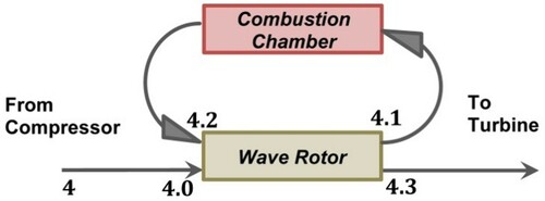
In the four-port configuration, schematically shown in Figure , when the hot exhaust gases out of the combustion chamber enter the wave rotor from the ‘hot’ port 4.2, they come in contact with the compressed air from the compressor which is already inside the rotor through the ‘cold’ port 4.0 having filled the space between the rotor blades. The result of this contact is the initiation of a compression wave which increases further the pressure of the air stream. As the wave is propagating along the rotor, it is reflected back from the endwall plate and is directed via the port 4.1 towards the combustion chamber. Simultaneously, an expansion wave is formed due to the contact of the streams of ‘cold’ air and ‘hot’ gases. It is propagating to the opposite direction (in respect to the compression wave), is reflected on the endwall plate and finally directed towards the turbine through the port 4.3. The circumferential location of the inlet and outlet ports of the rotor depends on the unsteady wave interaction inside the rotor (called wave diagram) and its rotational speed, which is about one-third the rotational speed of the high pressure turbine shaft. Okamoto et al. (Citation2004) present in detail the wave diagram inside four port wave rotors, by means of analytical and numerical calculations.
The wave rotor pressure ratio is a critical parameter that characterises the performance of the wave rotor and accordingly the performance of the topped gas turbine engine. It is defined as:
(1)
(1) This parameter delivers the extra compression inside the wave rotor of the air flow stream.
Stagnation temperature at the cold air port of the wave rotor, T4.0
(2)
(2) Stagnation temperature at the port towards the turbine,
(3)
(3) Stagnation pressure at the cold air port of the wave rotor
(4)
(4) where the term
includes the pressure losses at the ducts connecting the wave rotor to compressor, combustion chamber and turbine and the leakage losses occurring between the rotating part (rotor) and the stationary openings (ports) of the wave rotor.
Stagnation temperature at the wave rotor exit towards the combustion chamber, , is obtained by using isentropic efficiency of the compression process inside the wave rotor.
(5)
(5) where ηC is the compression efficiency inside the wave rotor.
Stagnation pressure at the combustion chamber outlet
(6)
(6) where the term
represents the pressure losses in the combustion chamber.
Stagnation temperature at the combustion chamber exit, , is obtained by using isentropic efficiency of the expansion process inside the wave rotor.
(7)
(7) where ηE is the expansion efficiency inside the wave rotor.
The pressure at the wave rotor outflow towards the turbine is given according to Wilson and Paxson (Citation1993) by:
The above relation is known in the literature (Wilson and Paxson Citation1993) as the characteristic of the wave rotor. Akbari and Müller (Citation2003b) have also used the above equation for a preliminary design of wave rotor.
Performance
Power consumed by the compressor,
(8)
(8) Power produced by the turbine
is used to drive the compressor
(9)
(9) Heat added by the fuel
(10)
(10) Power produced by the power turbine,
(11)
(11) Net power delivered by the engine,
(12)
(12) Specific power
(13)
(13) Thermal efficiency
(14)
(14) Specific fuel consumption,
(15)
(15)
The temperature of the metal used to manufacture turbine blades goes up to approximately 800–900°C, but the maximum surface temperature of blades has been increased up to 1000°C due to the recent application of thermal barrier coatings on blade surfaces, Moon et al. (Citation2018). The present thermodynamic model accounts for cooling the high pressure turbine in case TIT1300 K. Two possible solutions can be proposed for air cooling the high pressure turbine of the wave-rotor topped engine: If it is to be done by external cooling, it can only be achieved by subtracting air flow from the high pressure outflow port of the wave rotor having higher pressure and lower temperature than the exhaust gases directed to the turbine. This guarantees that no backflow is occurring; however the presence of exhaust gases at the outflow of port 4.1 according to Snyder (Citation1996) due to recirculation increases the temperature of the cooling fluid which is further mixed with the high temperature exhaust gases exiting the port 4.3 of the wave rotor and directed towards the turbine nozzles. Air at the compressor exit cannot be used for cooling purposes since its pressure is lower than the pressure of the exhaust gases in port 4.3 of the wave rotor.
If the turbine is to be cooled by internal (convective) cooling, air from the compressor can be extracted and directed inside the turbine nozzles and rotor blades, absorbing thus heat from the blade (Razak Citation2007).
The unsteady flow nature created by pressure wave propagation in the blade channels, does not allow mixing of air with exhaust gases inside the rotor, Weber (Citation1995). Exhaust gases from the combustion chamber (after expansion in the wave rotor) are directed towards the turbine through the port 4.3, Paxson et al. (Citation2007). Depending on the design of the baseline engine, alternative methods for the turbine cooling can be examined, however, the investigation of alternate cooling methods was not investigated as such was outside the scope of this study.
The quantity of the air mass flow rate to be used in the mixer in order to moderate the exhaust gas temperature can be calculated using an energy balance equation based on the inlet air flow rate, power output, efficiency, gas turbine outlet temperature and TIT according to the method proposed by Prasad et al. (Citation2016) and by Jonsson et al. (Citation2005). Turbine blades are normally made of nickel or rhenium alloys capable of withstanding high heat without distortion. The High Pressure Turbine airfoils as well as the Power Turbine airfoils can also be cooled. They can be made of INCO 738 coated with a silicon aluminide coating (Shepard et al. Citation1994).
Wave rotor two-shaft gas turbine analysis
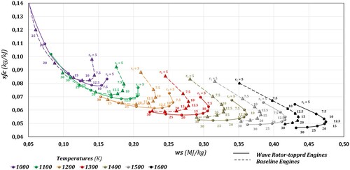
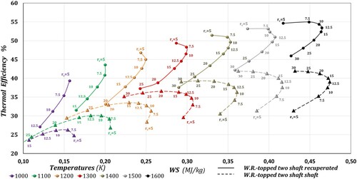
Figure presents the performance curves of wave rotor topped two-shaft gas turbines at design point for various values of rc and TIT, illustrated with continuous lines in comparison to the base line (without wave rotor) two-shaft gas turbines illustrated with dashed lines. These results correspond to PR = 1.8 and nE = nC = 0.83. The choice of these values is in agreement with data used by Wilson and Paxson (Citation1993) in early studies of wave rotor-topped gas turbine engine performance evaluation, as well as with data used in the most recent publications on wave rotors (Akbari and Müller (Citation2003a), Akbari et al. (Citation2006), Dempsey et al. (Citation2006), Fatsis (Citation2019)) and are considered as well established values in the literature.
Figure 4. Thermal efficiency percentage against specific power for baseline and wave rotor-topped two-shaft gas turbines (rc: compressor pressure ratio).
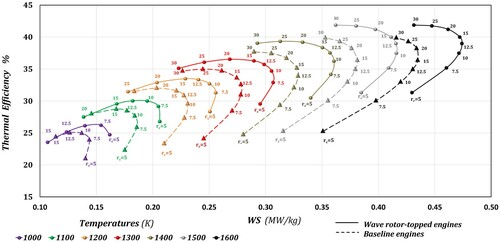
Dashed lines with triangular symbols illustrate the performance of the baseline engines, while continuous lines with spherical symbols of the same colour illustrate the performance of the wave rotor-topped two-shaft gas turbines.
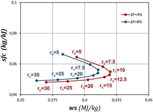
Each symbol in the diagram corresponds to the design point conditions of a specific two-shaft gas turbine. From this figure, it can be seen that for a given value of TIT, both thermal efficiency and specific power of wave-rotor topped engines are increasing with respect to their values of the base line engines. It is observed that the performance curves of the wave rotor-topped engines are shifted to the upper right part of the diagram. Similarly, Figure presents the sfc – ws distribution of wave rotor topped two-shaft gas turbines at design point conditions for various values of rc and TIT. One can observe that the performance curves of the wave rotor-topped engines are shifted to the lower right part of the diagram compared to the corresponding baseline gas turbines without wave rotor. Therefore the wave rotor integration, decreases baseline engine’s sfc and simultaneously increases its ws.
Figure 5. Specific fuel consumption against specific power for baseline and wave rotor-topped two-shaft gas turbines. (rc: compressor pressure ratio).
Figures and indicate that two-shaft gas turbines having low values of the compressor pressure ratio, rc, are more favourable to the integration of a four port wave rotor in terms of thermal efficiency, specific fuel consumption and specific power, especially at high values of TIT.
Figure shows qualitatively the effect of integrating a four-port wave rotor on two-shaft engines. In this figure, a typical case with PR = 1.8, nC = nE = 0.83 for TIT = 1500 K is presented. In the same figure, the percentage increase in ws and in nth are illustrated.
Figure 6: Increase in specific power (ws) and thermal efficiency (nth) for two-shaft gas turbines topped with four-port wave rotor with ηC = ηE = 0.83, PR = 1.8 for TIT = 1500 K (rc: compressor pressure ratio).
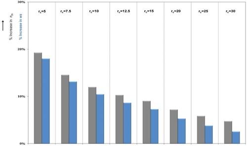
A clear benefit in terms of both ws and nth increase for all values of rc considered can be seen. More specifically, the prevalent increase in nth reaches 19.3% and in ws reaches 18% for compressor ratio rc = 5. This increase decays as rc increases, ending up to a minimum value of 4.8% and 2.6% for nth and ws, respectively, for engines of compression ratio rc = 30. This means that for all range of gas turbines there is a clear performance enhancement.
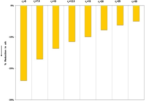
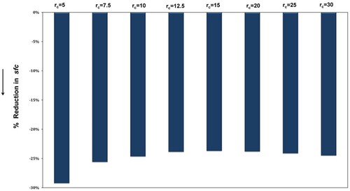
Figure shows qualitatively the effect on specific fuel consumption of two-shaft engines when integrating a four-port wave rotor. A typical case with PR = 1.8, nC = nE = 0.83 for TIT = 1500 K is presented. The major reduction in sfc is 23.9% for rc = 5, descending to 5% for rc = 30. Conclusively from Figures and , performance enhancement of two-shaft wave rotor-topped engines operating at design point conditions having TIT = 1500 K is maximised for low values of rc. Referring to Figures and , we conclude that the higher the TIT (especially for low values of rc) the more the benefits are for the engine’s performance.
Figure 7. Reduction in specific fuel consumption (sfc) for two-shaft gas turbines topped with four-port wave rotor with ηC = ηE = 0.83, PR = 1.8 for TIT = 1500 K (rc: compressor pressure ratio).
Parameters influencing performance of two-shaft gas turbines
Various studies carried out in the past, such as Jones and Welch (Citation1996), Welch et al. (Citation1999), Fatsis and Ribaud (Citation1999), Povinelli et al. (Citation2000) indicated that the main parameters influencing the performance of wave rotor topped two-shaft engines are:
Wave rotor pressure ratio (PR).
Pressure losses variation at the ducts connecting the wave rotor to compressor, combustion chamber and turbine (ΔPduct), confirmed in previous studies by Fatsis and Ribaud (Citation1999) and by Akbari and Müller (Citation2003a).
Effect of wave rotor pressure ratio variation on performance of two-shaft gas turbines
Numerical and experimental studies carried out by Jones and Welch (Citation1996), by Povinelli et al. (Citation2000) and by Okamoto and Araki (Citation2008) concluded that the operation of a four-port wave rotor is effective when its pressure ratio PR attains the value of 1.8.
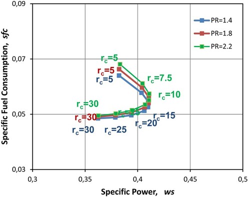
Figure presents the sfc – ws distribution for two-shaft gas turbines with TIT = 1500 K for three different values of PR = 1.4, 1.8 and 2.2. The PR variation has a slight effect on sfc for low compressor pressure ratio rc values, but no effect on ws. For rc > 10, the gas turbine performance is independent of the wave rotor pressure ratio PR. It is interesting to notice that for rc < 10, the case of PR = 1.4 results to slightly lower sfc and slightly higher ws than the one corresponding to the PR = 2.2 case. Therefore the influence of the wave rotor pressure ratio PR, has negligible effect on engine’s performance for TIT = 1500 K, when the rest of the parameters are kept unchanged.
Figure 8. Performance of two-shaft gas turbines topped with four-port wave rotor with ηC = ηE = 0.83, TIT = 1500 K and variation of PR from 1.4 to 2.2 (rc: compressor pressure ratio).
Effect of leakage and pressure losses variation
The effect of the pressure losses in ducts connecting the wave rotor to compressor, combustion chamber and turbine, as well as leakage losses at the extremities of the wave rotor (ΔPduct), was investigated experimentally by Wilson et al. (Citation2007). It was concluded that leakage deteriorates the performance of the wave rotor. Experiments revealed that reduction in mass flow of the order of 5% due to leakage, results to an equal reduction of the wave rotor pressure ratio. Measurements carried out by Hendricks et al. (Citation1997) using bidirectional brush seals between the rotor and the endwall plates indicate that the use of brush seals improve the wave rotor efficiency from 36 to 45 percent at low leakage (i.e. small rotor endwall gap spacing) and from 15 to 33 percent at high leakage (i.e. larger endwall gap spacing). Details on the aerodynamic design of the ducts connecting the wave rotor to the compressor, combustion chamber and turbine are discussed by Slater and Welch (Citation2005).
Leakage studies are incorporated to 1-Dimensional CFD codes by adding source terms only to the first and last cells of the computational domain formed inside the rotor channels. These terms affect only the continuity and energy equations, as is done by Paxson and Wilson (Citation1993), Fatsis et al. (Citation1998), Okamoto and Nagashima (Citation2007). Akbari et al. (Citation2008) presented a leakage quasi 1-Dimensional model taking into account the variations in pressure and temperature determining the local leakage circumferentially around the rotor.
Figure presents the sfc – ws distribution for the case where PR = 1.8, TIT = 1500 K, ηC = ηE = 0.83, for leakage and pressure losses ΔPduct = 4% and 8%. From this figure it can be seen that for TIT = 1500 K, when ΔPduct is increasing, ws is decreasing and at the same time sfc is slightly increasing. The effect of pressure losses is more apparent in low-pressure ratios. The higher the pressure ratio, the less important is the effect of the losses on engine’s performance.
Figure 9. Performance of two-shaft gas turbines topped with four-port wave rotor with PR = 1.8, ηC = ηE = 0.83 TIT = 1500 K, ducting and leakage pressure losses ΔPduct = 4%, 8% (rc: compressor pressure ratio).
Wave rotor two-shaft recuperated gas turbines analysis
In marine gas turbines, recent advancements with the WR-21 ICR engine showed that significant fuel savings can be achieved by introducing a recuperator in the baseline engine, English (Citation2003). This device recovers waste energy from the gas turbine exhaust, preheating the air entering the combustion chamber, improving cycle efficiency and reducing fuel consumption, Shepard et al. (Citation1994). Wang et al. (Citation2013), Chen et al. (Citation2013) proposed an analytical method for thermodynamic optimisation of a triple-shaft open ICR gas turbine. Ji et al. (Citation2017) proposed a comprehensive methodology to analyse the off-design performance of marine intercooled gas turbines.
Under this perspective, a through-flow four-port wave rotor can be introduced to the baseline gas turbine – recuperated cycle, as Figure illustrates.
Figure 10. Two-shaft recuperated Gas Turbine configuration, C: gas turbine compressor, T: turbine, CC: combustion chamber, WR: wave rotor, CT: compressor turbine, PT: power turbine, HE: heat exchanger (recuperator).
The thermodynamic calculation of the recuperator is based on an iterative procedure. Initially, the temperature of the ‘cold’ exit 5.2 of the heat exchanger is assumed (T05,hyp). Then fuel mass flow through the combustion chamber is:
(16)
(16) The ‘hot’ exit temperature of the recuperator (T10) is calculated as:
(17)
(17) where nHE is the efficiency of the recuperator (its value lies between 0.84 and 0.92).
The updated value of the ‘cold’ exit of the recuperator is calculated as:
(18)
(18) If the quantity
is less than a prescribed error (e.g. 0.001), then the calculation is converged, otherwise a new value
is assumed and a new iteration begins.
The pressure loss in the recuperator is expressed by means of the recuperator pressure loss that takes values between 1% and 4%.
The performance map of two-shaft wave rotor recuperated engines with respect to the corresponding two-shaft baseline recuperated engines at design point conditions is shown in Figure . Dashed lines with triangular symbols illustrate the performance of the baseline recuperated engines, while continuous lines with spherical symbols of the same colour illustrate the performance of the wave rotor-topped recuperated two-shaft gas turbines.
Figure 11. Thermal efficiency percentage against specific power for baseline and wave rotor-topped two-shaft recuperated gas turbines (rc: compressor pressure ratio).
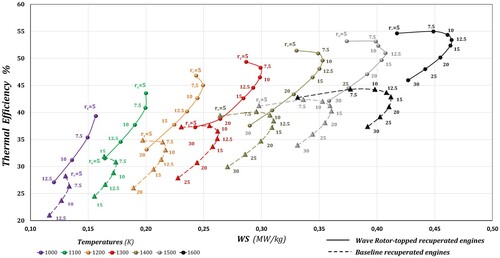
From Figure , it can be observed that for the case of two-shaft recuperated wave rotor-topped engines the integration of the wave rotor increases significantly the engine’s efficiency for both low and high values of rc. At higher TIT values, the performance curves of the topped engines recover their expected fish-hook shape.
Figure shows qualitatively the effect of integrating a four-port wave rotor on two-shaft recuperated engines. A typical case with PR = 1.8, nC = nE = 0.83 for TIT = 1500 K is illustrated. In the same figure, the percentage increase in nth is shown (the specific power, ws is not affected by the presence of the recuperator) and a net benefit in terms of nth increase for all values of rc is achieved. More specifically, the prevalent increase in nth reaches 22.6% for compressor ratio rc = 5, whereas the minimum increase is always higher than 19%. This increase is kept almost constant as rc increases, even for engines with rc = 25 or 30. Most of the aero-derivative gas turbines used for marine applications have compressor pressure ratios between 15 and 20. For all these engines, the gain in nth is greater than 19%. So the application of wave rotors to recuperated engines leads to important efficiency improvements.
Figure 12. Increase in thermal efficiency (nth) for two-shaft recuperated gas turbines topped with four-port wave rotor with ηC = ηE = 0.83, PR = 1.8 for TIT = 1500 K. (rc: compressor pressure ratio).
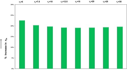
Figure shows qualitatively the effect on specific fuel consumption when integrating a four-port wave rotor on two-shaft recuperated engines. A typical case with PR = 1.8, nC = nE = 0.83 for TIT = 1500 K is presented. The decrease in sfc is 29.2% for engines with rc = 5, and for engines with rc = 20 it is 24%. It can be seen from Figures and that performance enhancement of two-shaft wave rotor-topped recuperated engines operating at design point conditions with TIT = 1500 K is maximised for low values of rc, but there is a net benefit which is kept almost constant independent of the value of compressor pressure ratio rc. For the typical value of TIT examined, the net benefit in terms of thermal efficiency is more than 19% (from Figure ) and the reduction in sfc is close to 24% for all compressor pressure ratio values examined, fact that makes the integration of a four-port wave rotor to a marine gas turbine recuperated engine even more attractive.
Figure 13. Reduction in specific fuel consumption (sfc) for two-shaft recuperated gas turbines topped with four-port wave rotor with ηC = ηE = 0.83, PR = 1.8 for TIT = 1500 K. (rc: compressor pressure ratio).
A comparison between the wave rotor-topped two-shaft recuperated gas turbines and the wave rotor-topped two-shaft gas turbines without recuperator is illustrated in Figure .
Figure 14. Comparison of performances between wave rotor-topped two-shaft recuperated (continuous lines) and wave rotor-topped two-shaft gas turbines (dashed lines) (rc: compressor pressure ratio).
One can observe that the thermal efficiency of wave rotor-topped two-shaft recuperated gas turbines, surpasses 50% for values of TIT≥1400 K, for small to moderate compression ratios and is comparable to combined cycle efficiencies, whereas the specific power attains almost the same value as the one calculated for the wave rotor-topped engines without recuperator. Benefits for wave rotor recuperated engines are observed for all values of rc and TIT. Taking as an example the case where TIT = 1500 K, a marine wave rotor-topped and recuperated gas turbine with rc = 15 have thermal efficiency of 50%. Similar thermal efficiency, of 47%, is attained for another wave rotor-topped recuperated gas turbine with rc = 20 having the same TIT. These two examples clearly indicate that wave rotor topping enhances considerably the efficiency of typical marine recuperated gas turbines.
Integration of wave rotor in gas turbines
The concept of a prototype wave rotor topped demonstrator engine using as baseline engine the Rolls-Royce Alison 250 turboprop was presented by Snyder (Citation1996) and by Welch et al. (Citation1999). The modification of the original engine to include a four-port wave rotor and the associated ducting, while keeping the original compressor, turbine and combustor was evaluated. The rotor diameter and length found to be approximately equal to the tip diameter of the high pressure turbine of the original engine. The wave rotor was planned to be mounted on a separate shaft between the turbine and combustor, spinning coaxially with the gas turbine shaft at approximately one-third the speed of the gas generator spool through its operating range. The topped engine was predicted to produce 11.4% more shaft power (+20% specific power) with a 22% decrease in engine’s sfc at design point conditions. According to Snyder (Citation1996), the greatest challenges of the topped engine are related to the re-design of the combustion chamber design and the design of the ducts connecting it to the wave rotor due to high temperatures.
Preliminary design estimates of marine gas turbines topped with four-port through-flow wave rotors
Based on the four-port wave rotor demonstrator engine designed by Snyder (Citation1996), a reasonable estimation of the ratio of the external to internal rotor diameter, (see Figure ) is
. Assuming 60 rotor blades and having as input: (i) the mass flow rate of the baseline engine, (ii) two (2) cycles of operation per rotation and (iii) the external diameter of the high pressure turbine, an approximation of the internal and external rotor diameter can be obtained. Exact dimensions of the circumferential extension of port openings can be acquired by calculating the wave diagram inside the rotor. This can be done either by: (a) numerical CFD calculations of the 1-Dimenional unsteady flow pattern inside the rotor considering various types of losses (e.g. Paxson and Wilson Citation1993; Fatsis et al. Citation1998; Okamoto and Nagashima Citation2007 and Akbari and Müller Citation2003b) or (b): analytical calculations of isentropic flow using the characteristics theory (Resler et al. Citation1994, Citation2001).
Figure 15. Typical rotor geometry, external diameter,
internal diameter,
rotor length.
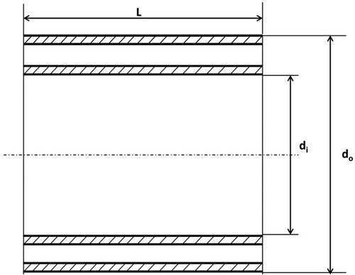
The integration of a four-port wave rotor to an existing aero-derivative gas turbine is expected to increase the overall length and width of the engine accounting for the rotor and the ducting connections with compressor, combustion chamber and high pressure turbine. Based on the mass flow rate of of a typical 25-MW engine, the rotor outside diameter could be
, the rotor internal diameter
and rotor length
. Figure shows a simplified cross section of the rotor geometry.
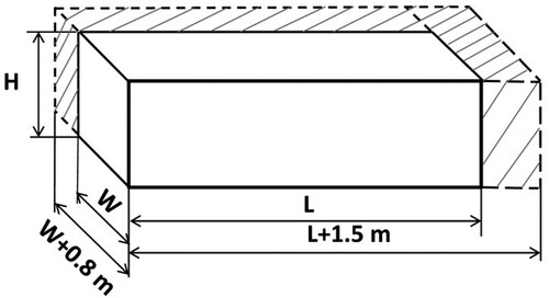
Typical dimensions of the GE LM2500 (GE Citation2018) are: length: 8.00 m, width: 2.74 m, height: 3.05 m and of the RR MT30 (RR Citation2020) are: length: 8.7 m, width: 2.7 m, height: 3.5 m. An increase of the engine’s length by 1.5 m (including the coupling of the rotor shaft) and its width by 0.80 m (due to the diameter of ducts required to transfer compressed air and exhaust gases to the rotor) is expected. The height of the topped engine is not likely to exceed its original value. Figure presents schematically the foreseen increase in dimensions of a typical 25–36 MW wave rotor-topped marine gas turbine.
Figure 16. Baseline (solid lines) and enhanced marine gas turbine expected dimensions.
Detailed investigation of the wave rotor-enhanced engine weight depends on the technical specifications of the engine. Welch et al. (Citation1995) suggest that an assessment of the weight added due to the wave rotor and associated ducting for the case of small and intermediate turboshaft engines (mass flow rates between 5 and 30 kg/s) is approximately 20% of the baseline engine core weight. The choice of materials used for the rotor, endwall plates, rotor casing and ducting, plays a key point to the overall weight estimation. Wilson et al. (Citation2007) used titanium for the rotor designed for a four-port wave rotor experiment at NASA Lewis. Typical alloys that can also be used are: Ti 6Al-4 V (alpha-beta alloy, Grade 5) with density of 4430 kg/m3 (Neonickel Citation2021) and alloy IN-738 with density of 8110 kg/m3 (Nickel Institute Citation2021). A rough estimation of the mass of the rotor depicted in Figure including the upstream and downstream endwall plates and the ducting, ranges between 300 and 400 kg depending on the material used. Taking as reference engines the GE LM2500 and the RR MT30, the extra weight due to the wave rotor is about 6% the weight of the unpacked baseline engine. Therefore, the overall mass of the baseline engine is not significantly differentiated by the addition of the rotor’s extra mass.
Performance benefits of existing marine gas turbines
The expected merits of wave rotors for marine propulsion systems consist of:
Increase of thermal efficiency.
Increase of specific power.
Reduction of specific fuel consumption.
Minor to medium increment of two out of three engine’s dimensions (length – width) with insignificant changes in height and mass.
Possibility of in-rotor constant volume combustion (Elharis et al. Citation2010), replacing the conventional combustion chamber of gas turbines.
Design and manufacturing of necessary ducting to connect the wave rotor to existing components of the gas turbine.
Cooling requirements of the ducts connecting combustion chamber exit to wave rotor ‘hot’ inlet port.
Fabrication of prototypes for experimental performance validation and wave rotor-topped engines design optimisation.
Table 3. Baseline and wave rotor-topped marine gas turbine performance.
Conclusion
In this article, the performance assessment of two-shaft gas turbine engines topped with a four-port through-flow wave rotor as a prime mover for naval ships was performed. Integration of wave rotor technology in marine gas turbines can moderate the fuel consumption and increase the specific power of the engine. Rough estimation of the extra weight of the wave rotor and associated ducting was found to increase the weight of typical marine aero-derivative engines by 6%. Previous references (Welch et al. Citation1995) discussing the wave rotor topping of small and medium turboshaft engines estimate the extra weight increase to 20%. This difference can be attributed to the fact that in small and medium-range engines the extra weight of the topped engine compared to the weight of the baseline engine is significant. For the typical marine aero-derivative engines examined, the topped engine weight increase is a small percentage of the naval ship deadweight and the extra dimensioning due to the wave rotor and the associated ducting is not expected to impose major changes in the machine room. In the thermodynamic model developed, the compressor, gas turbine and compressor turbine of the baseline engine are kept unchanged to keep the wave rotor’s integration cost low.
However, Akbari and Müller (Citation2003a) investigated other integration scenarios requiring the re-design of some of the baseline components that lead to similar performance benefits. In-rotor constant volume pressure gain combustion as new promising technology, however, presents some unique challenges (Akbari and Nalim Citation2009). Fundamental combustion patterns, ignition and flame control remain poorly understood so far. Unsteady combustion in the wave rotor channels involves complex flame–wave interactions fundamentally different from familiar internal combustion engines and steady-flow gas turbine combustion and they need extensive investigation (Nalim et al. Citation2017).
Ambient pressure and temperature, thermodynamic constants for the air and hot gases, thermal efficiencies for compressor, compressor turbine and power turbine as well as compression and expansion efficiencies for the processes inside the wave rotor, are the input data required for the calculations of the present model. Performance maps at design point illustrate the benefits of wave rotor-topped engines with respect to the corresponding baseline engines. Depending on the design requirements concerning specific power and specific fuel consumption, the topped engines maps help to select the most favourable engine and its precise operating conditions (compressor pressure ratio, TIT).
For two-shaft engines working at a given compressor pressure ratio, the higher the TIT is, the more the benefit gain of the wave rotor topped engine is attained in terms of thermal efficiency, specific fuel consumption and specific power. Assuming compression and expansion efficiencies inside the wave rotor, as well as ducting and leakage pressure losses specified by previous researchers, it was demonstrated that for typical marine aero-derivative engines listed in Table the increase in thermal efficiency remains higher than 6% and the increase in specific power remains higher than 5% at TIT = 1500 K.
The parameters selected as important for the performance of the wave rotor and of the topped engine are: The wave rotor pressure ratio and the ducting and pressure losses associated with the wave rotor. Each of these parameters is varied around a mean value which is well established in the literature and used by other researches in the past.
The influence of wave rotor pressure ratio (PR) on specific fuel consumption is negligible for rc > 10 for TIT = 1500 K. For all the cases examined no influence of PR variation on specific power was observed.
Leakage and pressure losses are mainly influencing specific power, while specific fuel consumption remains almost unchanged. Results showed that when the pressure losses increase, specific fuel consumption also increases whereas specific power decreases, for all values of compressor pressure ratios examined. The effect of pressure losses is more apparent for low-pressure ratios. The higher the pressure ratio, the minor the effect of losses on engine’s performance is.
For the case of wave rotor-topped recuperated marine gas turbine engines, the thermal efficiency increases by at least 19% and the specific fuel consumption decreases by at least 24% for all pressure ratios examined for the typical value of TIT = 1500 K with respect to the baseline recuperated engines. Peak thermal efficiency can exceed 50% for TIT≥1400 K at low values of the compressor pressure ratio. Efficiency and specific fuel consumption enhancement of marine recuperated wave rotor gas turbines attain significant levels even for large compressor pressure ratios, fact that makes attractive the integration of wave rotor to this type of engines.
The integration of four-port wave rotors to marine gas turbines has the potential to improve their performance, although there are challenges to be successfully surpassed.
Disclosure statement
No potential conflict of interest was reported by the author(s).
Additional information
Notes on contributors
Antonios Fatsis
Professor Antonios Fatsis is a Mechanical Engineer, graduated in 1989 from the University of Patras, Greece. He pursued post-graduate studies in the Turbomachinery Department of the “von Karman Institute for Fluid Dynamics” (VKI) in 1990 and obtained his Ph.D. degree in Applied Sciences in 1995. He worked as a research engineer at the Energetics Department of the “Office National d'Etudes et de Recherches Aérospatiales” (ONERA), France, until 1997. He acquired experience in the maritime industry working at Registro Italiano Navale SpA until 2005. In October 2005, he joined the Mechanical Engineering Department of the Technological University of Central Greece where he was appointed as the Head of the Internal Combustion Engine and Gas Turbine Laboratory. Since 2018 he is full Professor and faculty member of the General Department of the Kapodistrian University of Athens. He has published several journal and conference articles on topics related to internal combustion engines, turbomachinery, pumps and Computational Fluid Dynamics.
References
- Akbari P, Müller N. 2003a. Performance investigation of small gas turbine engines topped with wave rotors. AIAA Paper. 2003–4414.
- Akbari P, Müller N. 2003b. Preliminary design procedure for gas turbine topping reverse-flow wave rotors. Paper IGTC2003 Tokyo FR-301 presented at the International Gas Turbine Congress 2003 Tokyo, Japan.
- Akbari P, Nalim MR. 2009. Review of recent developments in wave rotor combustion technology. J Propuls Power. 25(4):833–844.
- Akbari P, Nalim MR, Donovan ES, Snyder PH. 2008. Leakage assessment of pressure-exchange wave rotors. AIAA J Propuls Power. 24:4, 732–740.
- Akbari P, Nalim MR, Müller N. 2006. A review of wave rotor technology and its applications. J Eng Gas Turbines Power. 128:717–735.
- Alvarez A, Coleman MJ, Ordonez J. 2015. Ship weight reduction and efficiency enhancement through combined power cycles. Energy. 93:521–533.
- Armellini A, Daniotti S, Pinamonti P. 2015. Gas turbines for power generation on board of cruise ships: a possible solution to meet the new IMO regulations?. Energy Procedia. 81:540–547.
- Barsi D, Bono A, Satta F, Zunino P. 2019. Gas turbine prime movers fuelled by LNG as a future alternative for sustainable power in marine propulsion: current emission policy assessment and exhaust quality evaluation, E3S Web of Conferences Vol. 113, Article No.02018.
- Barsi D, Costa C, Satta F, Zunino P, Busi A, Ghio R, Raffaeli C, Sabattini A. 2020. Design of a mini combined heat and power cycle for naval applications. J Sustain Dev Energy Water Environ Syst. 8(2):281–292.
- Benvenuto G, Campora U. 2003. Dynamic performance analysis of a gas turbine/waterjet propulsion system for a fast trimaran ferry, Int. Proceedings of the 7th Int. Conference on Fast Sea Transportation, Ischia, Italy.
- Benvenuto G, Campora U. 2005. A gas turbine modular model for ship propulsion studies, Int. Proceedings of the 7th Symposium on High Speed Marine Vehicles, Naples, Italy.
- Brady EF. 1988. Gas turbine systems for World Navy Ships. ASME Paper 88-GT-166.
- Campora U, Cravero C, Zaccone R. 2017. Marine gas turbine monitoring and diagnostics by simulation and pattern recognition. Int J Nav Archit Ocean Eng. 10(5):1–12.
- Chen L, Wang W, Sun F. 2013. Thermodynamic optimization of a triple-shaft open intercooled, recuperated gas turbine cycle. Part 1: description and modeling. Int J Low-Carbon Technol. 11:1–7.
- Cristall A, Parker ML. 1993. Overview of the WR-21 Intercooled Recuperated Gas Turbine Engine system. A modern engine for a modern fleet. ASME Paper 93-GT-231.
- Dempsey E, Müller N, Akbari P, Nalim MR. 2006. Performance optimization of Gas turbines utilizing four-port wave rotors. AIAA Paper. 2006–4152.
- Ebaid M, Al-hamdan Q. 2015. Thermodynamic analysis of different configurations of combined cycle power plants. Mech Eng Res. 5:2.
- Elharis TM, Wijeyakulasuriya SD, Nalim MR. 2010. Wave rotor combustor aero-thermodynamic design and model validation based on initial testing. AIAA Paper 2010-7041. 46th AIAA/ASME/SAE/ASEE Joint Propulsion Conference & Exhibit. Nashville, USA.
- English CR. 2003. The WR-21 intercooled recuperated gas turbine engine – integration into future warships, IGTC2003Tokyo OS-203. Proceedings of the International Gas Turbine 2003 Congress. Tokyo, Japan.
- Fatsis A. 2017. Parametric study on performance characteristics of wave rotor topped gas turbines. Int J Eng Res Technol (IJERT. 6(6):449–456.
- Fatsis A. 2018. Performance enhancement of one and two-shaft industrial turboshaft engines topped with wave rotors. Int J Turbo Jet Engines. 34(2):137–147.
- Fatsis A. 2019. Design point analysis of two-shaft gas turbine engines topped by four-port wave rotors for power generation systems. Propul Power Res. 8(3):183–193.
- Fatsis A, Lafond A, Ribaud Y. 1998. Preliminary analysis of the flow inside a three-port wave rotor by means of a numerical model. Aerosp, Sci Technol. 2(5):289–300.
- Fatsis A, Ribaud Y. 1999. Thermodynamic analysis of gas turbines topped with wave rotors. Aerosp Sci Technol. 3(5), 293–299.
- GE. 2018. [accessed 2021 Feb 2]. https://www.geaviation.com/marine/engines/military/lm2500-engine.
- Haglind F. 2008a. A review on the use of gas and steam turbine combined cycles as prime movers for large ships. Part I: Background and design. Energy Convers Manage. 49:3458–3467.
- Haglind F. 2008b. A review on the use of gas and steam turbine combined cycles as prime movers for large ships. Part II: Previous work and implications. Energy Convers Manage. 49:3488–3475.
- Haglind F. 2010. Variable geometry gas turbines for improving the part-load performance of marine combined cycles – gas turbine performance. Energy. 35:562–570.
- Hendricks RC, Wilson J, Wu T, Flower R. 1997. Bidirectional Brush Seals. NASA TM 107351.
- Horlock JH. 2003. Advanced gas turbine cycles. Pergamon: Cambridge.
- Iancu F, Müller N. 2005. Efficiency of shock wave compression in a microchannel. J Microfluid Nanofluid. 2(1):50–63.
- [IMO] International Maritime Organization. 2008. Marine Environment Protection Committee, MEPC 58/23/Add.1, Annex 14, RESOLUTION MEPC.177(58). Adopted on 10 October 2008, Amendments to the Technical Code on Control of Emissions of Nitrogen Oxides from Marine Diesel Engines.
- Ji N-k, Li S-y, Wang Z-t, Zhao N-b. 2017. Off-design behavior analysis and operating curve design of marine intercooled gas turbine. Math Probl Eng. Vol. 2017, pages 1 - 14, Article ID 8325040.
- Jones SM, Welch GE. 1996. Performance benefits for wave rotor-topped gas turbine engines. International Gas Turbine and Aeroengine Congress & Exhibition, Birmingham. Paper No. 96-GT-75.
- Jonsson M, Bolland O, Bücker D, Rost M. 2005. Gas turbine cooling model for evaluation of Novel Cycles. Proceedings of ECOS 2005, Trondheim, Norway.
- Kayadelen HK, Üst Y. 2013. Marine gas turbines. Proceedings of the 7th International Advanced Technologies Symposium (IATS’13), Istanbul, Turkey.
- Moon SW, Kwon HW, Kim TS, Kang DW, Sohn JL. 2018. A novel coolant cooling method for enhancing the performance of the gas turbine combined cycle. Energy. 160:625–634.
- Nalim MR, Snyder PH, Kowalkowski M. 2017. Experimental test, model validation, and viability assessment of a wave-rotor constant-volume combustor. AIAA J Propuls Power. 33:163–175.
- Neonickel. 2021. [accessed 2021 Feb 4]. www.neonickel.com ’ generate-alloy-pdf.
- Nickel Institute. 2021. [accessed 2021 Feb 4]. nickelinstitute.org’ in_738alloy_preliminarydata_497_.
- Okamoto K, Araki M. 2008. Shock wave observation in narrow tubes for a parametric study on micro wave rotor design. J Therm Sci. 17(2):134–140.
- Okamoto K, Nagashima T. 2007. Simple numerical modeling for gasdynamic design of wave rotors. J Propul Power. 23(1):99–107.
- Okamoto K, Nagashima T, Teramoto S. 2004. Multi-passage gasdynamic interactions in wave rotor. Proceedings of the 24th International Congress of the Aeronautical Sciences. Tokyo, Japan.
- Parker ML, MacLeod PK, Coulson M. 1998. Advances in a gas turbine system for ship propulsion. RTO AVT. Gas Turbine Engine Combustion, Emissions and Alternative Fuels. Vol. MP-14, Lisbon, Portugal, NATO, Session I, Paper No.2.
- Paxson DE, Wilson J. 1993. An improved numerical model for wave rotor design and analysis. NASA TM 105915, AIAA Paper 93-0482.
- Paxson DE, Wilson J, Welch GE. 2007. Comparison between simulated and experimentally measured performance of a four port wave rotor. NASA/TM-2007-214985, ARL-TR-4202, AIAA Paper-2007-5049.
- Povinelli LA, Welch GE, Bakhle MA, Brown GV. 2000. Potential application of NASA Aerospace technology to ground-based power systems. NASA TM 2000-209652.
- Prasad KB, Chand VT, Kumar N, Ravindra K, RAO VNB. 2016. Thermodynamic analysis of air cooled gas turbine in marine applications. Int J Therm Technol. 6(1):32–39.
- [RAENG] Royal Academy of Engineering. 2013. Future ship powering options. [accessed 2021 Feb 2]. https://www.raeng.org.uk/publications/reports/future-ship-powering-options.
- Razak AMY. 2007. Industrial gas turbines, performance and operability. Cambridge: Woodhead.
- Resler EL. 2001. Shock wave propulsion. Int J Chem Kinet. 33(12):846–852.
- Resler EL, Mocsari JC, Nalim MR. 1994. Analytic design methods for wave rotor cycles. J Propul Power. 10(5):683–689.
- RR. 2020. [accessed 2021 Feb 2]. https://www.rolls-royce.com/products-and-services/defence/naval/gas-turbines/mt30-marine-gas-turbine.aspx.
- Shepard SB, Bowen TL, Chiprich JM. 1994. Design and development of the WR-21 intercooled recuperated (ICR) marine gas turbine. ASME Paper 94-GT-79.
- Slater JW, Welch GE. 2005. Design of a wave-rotor transition duct. AIAA Paper 2005-5143.
- Snyder PH. 1996. Wave rotor demonstrator engine assessment. NASA CR 198496.
- Stapersma D, Woud HK. 2005. Matching propulsion engine with propulsor. propulsor. J Mar Eng Technol. 4(2):25–32.
- Thomson GA, Pratley DJ, Owen DA. 1987. Intercooling and regenerating the modern marine gas turbine propulsion system. SAE Trans. 96:169–175.
- Wang W, Chen L, Sun F. 2013. Thermodynamic optimization of a triple-shaft open intercooled, recuperated gas turbine cycle. Part 2: power and efficiency optimization. Int J Low-Carbon Technol. 11:29–34.
- Weber HE. 1995. Shock wave engine design. New York (NY): John Wiley and Sons.
- Welch GE, Jones SM, Paxson DE. 1995. Wave rotor-enhanced gas turbine engines. NASA TM 106998.
- Welch GE, Paxson DE, Wilson J, Snyder PH. 1999. Wave-rotor-enhanced gas turbine engine demonstrator. NASA TM 209459.
- Wilson J, Paxson DE. 1993. Jet engine performance enhancement through use of a wave-rotor topping cycle, NASA TM 4486.
- Wilson J, Welch GE, Paxson DE. 2007. Experimental results of performance tests on a four-port wave rotor, NASA/TM-2007-214488, ARL-TR-4044.
- Woodyard D. 2004. Pounder’s marine diesel engines and gas turbines, 8th ed. Elsevier Inc.