
 ?Mathematical formulae have been encoded as MathML and are displayed in this HTML version using MathJax in order to improve their display. Uncheck the box to turn MathJax off. This feature requires Javascript. Click on a formula to zoom.
Abstract
Electrospun fibers have received significant interests for various application areas such as filtration, composites and biomedical products due to their large surface area, good continuity, high porosity and many other unique properties. In bio-related applications, electrospun fibers have been used for in-situ drug delivery, tissue engineering scaffolds and wound dressing. In more recent years, there has been a drive toward novel electrospun fibers with added functionalities. Nanoengineering of electrospun fibers has introduced many of such novel properties. Through this review, researchers are provided with a state of the art overview of nanoenhanced electrospun fibers with added functionalities. Examples of some nanoengineered fibers include; surface functionalization, multi-component fibers, porous nanofibers, the creation of surface nano-topographies, and the incorporation of nanoparticles to create hierarchical fibrous structures for tailoring of physicochemical properties with a special focus on biomedical applications.
Graphical Abstract
1. Introduction
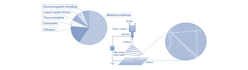
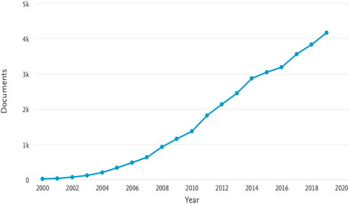
Nanoengineering refers to the engineering at the nano-scale. Materials engineered at the nano-scale possess fundamental differences compared to macro-scale materials due to their size effect. The extraordinary properties of nanomaterials have been investigated and applied to chemical, physical and biological areas [Citation1–3]. For example, Ma et al. designed nonmetal flexible oxygen electrodes of excellent performance by growing phosphorous-doped graphitic carbon nitride on carbon-fiber paper [Citation4]. Berthelot et al. fabricated nano-tweezers (metal-coated optical fibers with bowtie nano-apertures) that were able to trap and manipulate 50 nm sized nanoparticles [Citation5], while Gujrati et al. reported the preparation of bacterial outer membrane vesicles with low immunogenicity and cancer cell targeting properties [Citation6]. When searching the literature, many cutting-edge nanostructures have been achieved by either spontaneous or directed assembly [Citation7,Citation8]. Among different nanostructures, 1D nanomaterials like nanotubes, nanorods, nanowhiskers and nanowires (to name a few) have been extensively reported and applied to mechanics, electronics and energy realm [Citation9–12]. Synthesis of these 1D nanomaterials usually requires bottom-up techniques, which provide people with fascinating ways to exploit nanotechnology. On the other hand, most bottom-up manufacturing processes are nevertheless considered to induce high costs. Facile and cost-effective top-down methods like electrospinning are therefore becoming an attractive alternative in producing 1D nanomaterials. In addition, electrospinning is able to produce continuous fibers, which are difficult to realize via other bottom-up methods. Electrospun fibers have been widely reported for applications in areas like sensors, composites, filtration, decontamination, energy storage, catalysis [Citation13–15], but have received particular interest from the biomedical field for applications in wound dressing, drug delivery or tissue engineering [Citation15–20]. Since its first development in the 1930s, electrospinning has become a convenient and easy way to produce micro- or nano-scale fibers, with over three thousand papers on electrospinning-related topics published every year since 2015 (see ). During a typical electrospinning process, polymer solution or melt is supplied to a spinning tip or spinneret at constant rate. A droplet is formed at the spinning tip and a high voltage is applied to the spinneret which accumulates charges on the droplet to form a Taylor cone when the electrostatic force is sufficient to overcome the droplet surface tension. A fluid jet is ejected from the Taylor cone tip toward a grounded collector, during which the fluid jet solidifies and forms fibers. Randomly distributed fiber mats are obtained on a static collector while oriented fibers are achieved on specific rotating collectors [Citation21–23] or by using auxiliary set-ups and post-processing [Citation24,Citation25]. Electrospinning is optimized by controlling parameters like solution/melt viscosity, feeding rate and electric field. High viscosity and slow feeding rate will result in spinneret blockage while low viscosity and high feeding rate will lead to discontinuity of fibers or droplets. The electric field has to be properly set as a high field strength will decrease the time for fluid jets to solidify while low field strength is unable to form a Taylor cone. Ambient conditions like temperature and humidity are also to some degree influencing electrospinning [Citation26]. Although the field of electrospinning is by far the most active, in recent years, alternative methods to electrospinning have emerged for the production of polymer nanofibers such as rotary jet spinning or centrifugal spinning [Citation27–29], island in the sea spinning [Citation30,Citation31] and melt blowing [Citation32].
Figure 1. Number of publications per year with electrospinning or electrospun as keywords from 2000 to 2019 (source: Scopus).
The electrospinning technique has been extensively studied and many reviews have comprehensively summarized the electrospinning processing technique and its potential applications [Citation33–37]. However, reviews on the nanoengineering and application of nanostructured or nanoenhanced electrospun fibers are more difficult to find. Zhang and Yu reviewed the fabrication of nanoparticle-electrospun fiber composites, in which they summarized different techniques to obtain anisotropic fibers with nano-features using nanoparticles as well as their applications for energy, mechanics and sensors [Citation38]. The incorporation of nanoparticles has introduced significantly interesting nanostructures and novel properties into conventional electrospun fibers. In addition to using nanoparticles, nanoengineered electrospun fibers can also be obtained by developing new electrospinning techniques or functionalization. Yang et al. reviewed in-depth the fabrication of hierarchical electrospun fibers with 1D, 2D and 3D structures via specially-designed electrospinning devices and parameters; they also well discussed the hierarchical structures’ effect on biomedical applications [Citation39]. In the current review, we will first discuss different nanoengineering techniques and methodologies for electrospun fibers. In addition to customizing electrospinning devices and parameters, we also include post-processing, surface treatments (chemical and physical) and the use of nanoadditive or nanoparticle enhanced electrospun fibers. Finally we introduce briefly some applications of these fibers with a special focus on biomedicine and conclude with some perspective on future work.
2. Nanoengineering of electrospun fibers
2.1. Modifications of electrospinning set-ups and conditions
Traditional electrospinning is optimized by appropriately selecting experimental parameters, including spinning solution/melt viscosity, electrical field, feeding rate, ambient condition as well as the intrinsic properties of the polymer melt or solvent. Changes in parameters can result in fiber defects or even failure to spin fibers. However, it was found that through tuning these parameters, fibers with nanostructural features can be obtained. Over a decade ago, researchers have already successfully electrospun fibers with nano-size pores by using highly volatility solvents [Citation40,Citation41]. Formation of the porous structure was explained by rapid phase separation during electrospinning, which generated solvent rich areas that later transformed into pores. It was also believed to be related to air humidity, leading to the formation of water droplets in rapidly-cooled spinning jets due to solvent evaporation. In addition to humidity controlled porous fiber structures, hierarchically nanostructured fibers were also fabricated by using specific solvent combinations [Citation42]. Selection of an appropriate polymer-solvent system has shown to yield porous fibers due to phase separation with different types of porosity being generated by different phase separation mechanisms [Citation43,Citation44]. Nanoporous electrospun fibers were also achieved by using low molecular weight polymers. Lin et al. electrospun different molecular weight polystyrenes (PS) and found that lowering of the molecular weight led to porous nanostructures [Citation45]. They believed that lower molecular weights accelerated solvent evaporation and diffusion and caused further rapid phase separation at the fluid jet surface. Using selective solvents, they were also able to generate other secondary surface textures in addition to pores. Liu et al. electrospun PS fibers with grooved surface textures by using a series of solvent systems [Citation46]. These grooved textures were considered to be attributed to surface void stretching, wrinkle stretching, or collapse jet stretching. Ambient conditions (temperature and humidity) are known to affect the electrospun fiber’s surface structure [Citation47]. Temperature influences solvent evaporation rate while humidity is determining the imprints left by water droplets on the fluid jet surface. Li et al. developed a fabrication process for porous polycaprolactone (PCL) fibers by combining the principles of thermally induced phase separation with the use of a cryogenic electrospinning device which solidified the polymer jet on the freezing collector. Surface pores exhibited two types: pits and polygon concaves, where pits were induced by phase separation at freezing point and polygon concaves were the result of the interaction of residual solvent with ice crystals [Citation48]. Potential applications of electrospun porous fibers range from tissue engineering and drug delivery, to water treatment, sensors, photocatalysis and lithium-ion batteries [Citation44]. Some nanostructured electrospun fibers are presented in . Although manipulating electrospinning parameters seem an easy way of obtaining nanostructured electrospun fibers, the nanostructures it offers are relatively limited and less reproducible. More precise control and quantification of nanostructures needs other more sophisticated methodologies.
Figure 2. (a) SEM image of electrospun PS fibers from 20% PS solution in THF, spinning at 4 ml/h, 20 kV and 15 cm distance (adapted from ref. [Citation45]); (b) SEM image of electrospun PS fibers from 15% PS solution in BuOH/DCM 1/3, spinning at 1.5 ml/h, 12 kV and 15 cm distance (adapted from ref. [Citation46]); (c) SEM image of electrospun poly(methyl methacrylate) (PMMA) fibers from 12 wt% PMMA solution in N,N-dimethylacetamide/acetone 6/4, spinning at 0.8 ml/h, 15 kV and 15 cm distance (adapted from ref. [Citation42]); (d) SEM image of electrospun PS fibers from 15% PS solution in THF/DMF 1/1, spinning at 1.5 ml/h, 12 kV and 15 cm distance (adapted from ref. [Citation46]).
![Figure 2. (a) SEM image of electrospun PS fibers from 20% PS solution in THF, spinning at 4 ml/h, 20 kV and 15 cm distance (adapted from ref. [Citation45]); (b) SEM image of electrospun PS fibers from 15% PS solution in BuOH/DCM 1/3, spinning at 1.5 ml/h, 12 kV and 15 cm distance (adapted from ref. [Citation46]); (c) SEM image of electrospun poly(methyl methacrylate) (PMMA) fibers from 12 wt% PMMA solution in N,N-dimethylacetamide/acetone 6/4, spinning at 0.8 ml/h, 15 kV and 15 cm distance (adapted from ref. [Citation42]); (d) SEM image of electrospun PS fibers from 15% PS solution in THF/DMF 1/1, spinning at 1.5 ml/h, 12 kV and 15 cm distance (adapted from ref. [Citation46]).](/cms/asset/b5f19754-c4e6-4599-af7b-46a9d93fbba0/ynan_a_1857121_f0002_b.jpg)
In addition to manipulating electrospinning parameters, the use of specific electrospinning set-ups has also rendered nanostructured fibers. Schematics showing specific electrospinning set-ups and their produced fibers are shown in . Coaxial electrospinning is a well-known electrospinning technique in which two immiscible liquids are supplied through a coaxial duel capillary spinneret [Citation14,Citation49–51]. In this process both core and shell fluids are simultaneously undergoing bending instabilities, stretching and elongation to finally form continuous core-shell structured fibers [Citation52]. Core-shell electrospun fibers can also be obtained by free surface electrospinning where wired electrodes are placed in a liquid bath consisting of two immiscible liquid layers [Citation53]. Multi-channel tubular structures can be produced by feeding two immiscible fluids separately through an inner and outer capillary [Citation54]. Dror et al. demonstrated the ability to fabricate polymeric microtubes through co-electrospinning of core and shell polymeric solutions. The mechanism by which the initial core-shell structure is transformed into hollow fibers or microtubes were primarily based on the evaporation of the core solution through the shell [Citation55]. McCann and colleagues reported the fabrication of highly porous fibers by immersing the collector in a cryogenic liquid. Electrospun fibers were directly deposited in liquid nitrogen. The porous fibers were the result of phase separation between solvent-rich and solvent-poor areas followed by the removal of solvent after spinning [Citation56]. Electrospun fibers with nanorods deposited on their surface were reported by Chen et al. They electrospun PMMA fibers on an anodic aluminum oxide template and thermally annealed the fibers. During annealing PMMA was drawn into the nanopores by a capillary force and nanorods formed on the fiber surface after removing the template [Citation57]. The use of specific spinning set-ups allowed for the production of fibers with nanostructures which are difficult to achieve by tuning polymer solution properties or humidity/temperature. These nano-tubular structures inspired great interests and application as template, carrier, etc. Moreover, the nanostructures they built became more quantifiable and controllable. However as a result, the spinning requires specific set-ups, which are not as accessible as traditional electrospinning set-ups. In addition, the spinning becomes more sensitive and difficult as more electrospinning factors emerge. Further disadvantages also include the low output that restricts their scaled-up production, although in recent years significant progress has been made toward industrial scale production of electrospun fibers [Citation58].
Figure 3. (a1) Coaxial electrospinning and (a2) TEM image of core-shell electrospun fiber (adapted from ref. [Citation52]); (b1) multi-channel electrospinning and (b2) TEM image of multi-channel tubular electrospun fiber (adapted from ref. [Citation54]); (c1) free surface electrospinning and (c2) TEM image of core-shell electrospun fiber (adapted from ref. [Citation53]); (d1) electrospinning in cryogenic liquid and (d2) TEM image of electrospun porous fiber (adapted from ref. [Citation56]); (e1) electrospun fiber with nanorods structure and (e2) SEM image of fiber (adapted from ref. [Citation57]).
![Figure 3. (a1) Coaxial electrospinning and (a2) TEM image of core-shell electrospun fiber (adapted from ref. [Citation52]); (b1) multi-channel electrospinning and (b2) TEM image of multi-channel tubular electrospun fiber (adapted from ref. [Citation54]); (c1) free surface electrospinning and (c2) TEM image of core-shell electrospun fiber (adapted from ref. [Citation53]); (d1) electrospinning in cryogenic liquid and (d2) TEM image of electrospun porous fiber (adapted from ref. [Citation56]); (e1) electrospun fiber with nanorods structure and (e2) SEM image of fiber (adapted from ref. [Citation57]).](/cms/asset/acafc69b-1757-4415-a58d-369bd63ae43a/ynan_a_1857121_f0003_c.jpg)
2.2. Post-processing of electrospun fibers
Instead of direct electrospinning of nanostructured fibers, post-processing has also proven to be a powerful tool of creating secondary structures on normal electrospun fibers. Some previously reported techniques that introduce such nanostructure are shown in . For example, it was found that by drawing electrospun fibers, ripple-like features can be introduced on the fiber surface. These surface features are considered to occur due to the mismatch in Poisson’s ratio between the fiber’s dense and glassy core and the flexible rubbery shell [Citation59,Citation60]. Non-spherical cross-section fibers were obtained by pressing at elevated temperature using flat or nano-patterned substrates [Citation61]. Hollow fibers were produced by removing core material from core-shell fibers. Müller et al. prepared hollow polyethylene (PE) fibers by removing the polyvinyl alcohol (PVA) core from core-shell electrospun PE/PVA fibers. It is worth noting that these core-shell structured PE/PVA fibers were fabricated by electrospinning PVA fibers followed by PE polymerization on the PVA fiber surface [Citation62]. This not only produces hollow fibers, but also provided a new route of building core-shell structures. Rather than polymerization on fiber surfaces, Haider et al. performed atomic layer deposition and successfully fabricated aluminum nitride/boron nitride (AIN/BN) bi-shell hollow nanofibers. These bi-shell hollow structures were achieved by first electrospinning nylon 6,6 fibers followed by atomic layer deposition before calcination to remove the polymeric core [Citation63]. Dogan et al. described a single-needle electrospinning technique based on bead formation for the production of hollow PVA nanofibers. Results showed that parameters such as the voltage, collector distance and solution concentration had significant effect on shell morphology [Citation64]. Saetia et al. deposited multi-wall carbon nanotubes (MWNT) on electrospun fibers using a layer-by-layer (LbL) assembly of oppositely-charged MWNTs, building multi-layer MWNT coatings on fiber surfaces [Citation65]. Shish-kebab structures have also been formed by electrospinning and subsequent crystallization. Jing et al. reported the fabrication of shish-kebab structured PCL fibers decorated with chitosan-PCL copolymers. The introduction of biomolecules and topography showed enhanced cell attachment and viability [Citation66]. Chemical modification has also been considered as a facile way of achieving nanostructured fibers. Che et al. reported electrospun fibers of poly(methyl methacrylate)-block-poly[N,N-(dimethylamino) ethyl methacryate] (PMMA-co-PDEAEMA) whose surface roughness was modified by exposure to CO2 [Citation67]. Devarayan et al. produced fibers with nanospicules structures by treating electrospun cellulose fibers with NaOH and aluminum foil. The nanospicules were believed to be caused by the elemental hydrogen that was generated from NaOH-aluminum corrosion, destructing the glycoside bonds in the cellulose backbone [Citation68]. In addition, electrospun fiber surface textures can also be developed by plasma treatment, chemical etching or photo-embossing [Citation69–71]. Hughes-Brittain et al. recently introduced extracellular matrix (ECM) inspired relief textures onto electrospun fibers by electrospinning of reactive poly(methyl methacrylate)—trimethylolpropane ethoxylate triacrylate (PMMA-TPETA) photopolymer blends followed by photoembossing using interference of two coherent UV laser beam and thermal development [Citation71]. Results showed that this technique can be used for the texturing of electrospun fiber surfaces, with pitches as low as 500 nm and heights between 30 nm and 500 nm. Moreover, the developed technology based on pulsed laser interference holography has potential for integration into continuous electrospinning processes. Post-processing provides alternative ways to add nanofeatures to electrospun fibers. Using post-processing, it becomes possible to improve nanostructured fibers’ output by using conventional electrospinning technology combined with additional treatments. Novel surface topography can be engineered on electrospun fibers in a relatively easy manner. However, limitations still exist. For most hollow fibers, they still depend strongly on the coaxial electrospinning technique. Polymerization or coatings can be used to achieve core-shell structures, but there is a concern that the process (and also other treatment) are likely to damage the electrospun fiber’s initial properties or integrity (such as continuity), while their efficiency is also considered to be relatively low.
Figure 4. (a) SEM image of fibers with relief texture, produced by photoembossing (adapted from [Citation71]); (b) surface morphology of fast drawn polyacrylonitrile (PAN) nanofiber (adapted from [Citation59]); (c) SEM image of PCL fiber decorated with shish-kebab nanostructure (adapted from ref. [Citation66]); (d) SEM image of electrospun cellulose nanofiber using 0.1 M NaOH solution (adapted from ref [Citation68]); (e) TEM image of hollow ultra-high molecular weight polyethylene (UHMWPE) nanofibers (adapted from ref. [Citation62]); (f) SEM image of aluminum nitride (AlN) hollow nanofibers synthesized by depositing AlN followed by calcination (adapted from ref. [Citation63]).
![Figure 4. (a) SEM image of fibers with relief texture, produced by photoembossing (adapted from [Citation71]); (b) surface morphology of fast drawn polyacrylonitrile (PAN) nanofiber (adapted from [Citation59]); (c) SEM image of PCL fiber decorated with shish-kebab nanostructure (adapted from ref. [Citation66]); (d) SEM image of electrospun cellulose nanofiber using 0.1 M NaOH solution (adapted from ref [Citation68]); (e) TEM image of hollow ultra-high molecular weight polyethylene (UHMWPE) nanofibers (adapted from ref. [Citation62]); (f) SEM image of aluminum nitride (AlN) hollow nanofibers synthesized by depositing AlN followed by calcination (adapted from ref. [Citation63]).](/cms/asset/cc594f09-0797-4f4a-98d5-e12d15c9abf5/ynan_a_1857121_f0004_c.jpg)
2.3. Emulsion electrospinning
Most of the core-shell or multi-component electrospun nanofibers described above are manufactured using either specifically designed spinnerets or coating techniques and processes which are fairly complicated compared to conventional electrospinning. Because of this, emulsion electrospinning was developed where dispersion droplets are spun from polymer solutions into fibers. These dispersion droplets undergo stretching and elongation similar to the main spinning fluid jet. Chen et al. produced porous electrospun TiO2 fibers by electrospinning an emulsion of metal alkoxide (continuous phase) and paraffin oil (dispersed phase) followed by calcination (see ) [Citation72]. Pore sizes varied from nano to macro-scale, and were the result of demulsification and merging of small dispersion droplets. Due to stretching during electrospinning, the pores elongate along the fiber direction with lengths up to hundreds of nanometers. Wang et al. electrospun core-shell fibers by using emulsions consisting of PS/limonene (continuous phase) and bovine serum (dispersed phase). The relationship between fiber morphologies and polymer molecular weight was also investigated [Citation73]. The use of higher molecular weight PS resulted in an increase of the viscosity of the organic phase and a reduced mobility of the emulsion droplets. Hence, droplets were more likely to be located close to or even absorbed onto the fiber surface (see ). Huang et al. used emulsion electrospinning as well as coaxial electrospinning for the preparation of continuous nanofibers with a core-shell or hollow nanostructure [Citation74]. Emulsion electrospinning enables the fabrication of core-shell or multi-channel nanostructures in fibers without the need of any auxiliary equipment or complex spinnerets. Fibers with hierarchical structures can be achieved after removing one or more components [Citation75]. Electrospun core-shell PCL/chitosan composite nanofibers were also prepared by an emulsion system. A surfactant-free and low toxic water-in-oil emulsion was used by Ma et al. as the electrospinning precursor, while stability of the emulsion was achieved by adjusting the polymer to solvent concentration. PCL/chitosan fibers with different core to shell ratios were obtained by adjusting the PCL and chitosan concentration in the emulsion system [Citation76]. Emulsion electrospinning is also considered to be a safe method for biomedical applications, especially when encapsulating biomolecules in emulsion droplets. By separating biomolecules from harmful electrospinning solvents, it significantly decreases the potential of contamination to biomolecules or even further danger in bio-related applications. The main issue of emulsion electrospinning is concerned with the stability of the emulsion. They are kinetically stable although after a certain time destabilization can occur via various mechanisms, finally leading to phase separation [Citation77]. Moreover, challenges still exist in the control over emulsion size, especially to obtain nano-emulsions and their size distribution. Highly stable and size-controlled nano-emulsions are desired in order to optimize emulsion electrospinning for nanostructured fibers.
Figure 5. (a) SEM image of porous TiO2 fiber via emulsion electrospinning (adapted from ref. [Citation72]); (b) TEM image of core-shell fiber via emulsion electrospinning (image size 2 × 2 µm, adapted from ref. [Citation73]); (c) Schematic representation of core-shell formation during emulsion electrospinning (adapted from ref. [Citation30].
![Figure 5. (a) SEM image of porous TiO2 fiber via emulsion electrospinning (adapted from ref. [Citation72]); (b) TEM image of core-shell fiber via emulsion electrospinning (image size 2 × 2 µm, adapted from ref. [Citation73]); (c) Schematic representation of core-shell formation during emulsion electrospinning (adapted from ref. [Citation30].](/cms/asset/d74cdc38-ce3c-4d1c-9277-35853856856f/ynan_a_1857121_f0005_c.jpg)
2.4. Phase-separation electrospinning
In contrast to emulsion electrospinning, in which phase separation means destabilization of emulsion systems, phase-separation electrospinning is a spinning technique that uses liquid-liquid phase separation to fabricate internal structures within fibers. Wang et al. developed core-shell electrospun fibers by spinning homogeneous solutions followed by thermally induced phase separation of polyvinylpyrrolidone/polyvinylidene fluoride (PVP/PVDF) () [Citation78]. The core/shell material is determined by component surface energy and blend ratio, where the lower surface energy component tends to migrate to the fiber surface during electrospinning. A related approach to achieve porous fibers is known as non-solvent induced phase separation and involves the use of a combination of a good solvent and non-solvent to induce thermodynamic instabilities during electrospinning. Katsogiannis et al. electrospun porous PCL fibers using a PCL chloroform/dimethyl sulfoxide (DMSO) solution [Citation79]. The precipitation of a PCL-rich phase formed the main fiber while the PCL-poor phase formed cavities. Compared with humidity induced porosity, this method has better control over fiber morphologies. Nayani et al. directly electrospun fibers into a non-solvent bath. The solvent exchange between residual solvent in fiber and non-solvent was found to give porous fibers [Citation80]. Zhang and Mele showed that thermodynamic instabilities during electrospinning of polymer blends of poly(ethyl cyanoacrylate) (PECA) and PCL in a ternary solvent system (acetone/chloroform/acetonitrile) resulted in the formation of hierarchical composite fibers with two distinct morphologies: half of the fibers exhibited parallel and elongated grooves; whereas the other half had near-circular shaped pores [Citation81]. It was also found that an electrical field could enhance phase separation of electrolyte based solutions during electrospinning. Chen et al. designed glass spinnerets with a high gradient electric potential applied inside the spinneret (schematic shown in ), which drove hyaluronic acid molecules toward the opposite direction of the electric field and formed the core [Citation82]. Using this modified spinneret, they obtained core-shell structured polyethylene oxide/hyaluronic acid (PEO/HA) nanofibers. It was also reported that multi-jet structured electrospun fibers were prepared via phase separation [Citation83]. Phase separation electrospinning is a simple way of producing nanostructured fibers which usually does not require specifically designed equipment or complicated processing. By electrospinning homogeneous polymer solutions like conventional electrospinning, nanostructures are achieved. However, according to what has been reported, only a limited number of morphologies were produced. Moreover, phase separation electrospinning only applies to certain material combinations or solvent systems; while the size of the phase-separated morphology is highly depended on rapid solvent evaporation and usually cannot reach <10 nm.
Figure 6. (a) TEM image of PVP/PVDF core-shell nanofibers via electrospinning (PVDF/PVP = 1/3) (adapted from [Citation78]); (b) TEM image of highly porous PAN fibers by electrospinning into non-solvent bath (adapted from [Citation80]); (c) schematic showing the electric field induced phase separation during electrospinning and the core-shell PEO/HA fibers (adapted from [Citation82]).
![Figure 6. (a) TEM image of PVP/PVDF core-shell nanofibers via electrospinning (PVDF/PVP = 1/3) (adapted from [Citation78]); (b) TEM image of highly porous PAN fibers by electrospinning into non-solvent bath (adapted from [Citation80]); (c) schematic showing the electric field induced phase separation during electrospinning and the core-shell PEO/HA fibers (adapted from [Citation82]).](/cms/asset/94aedddf-a681-4691-abd0-c898f4575841/ynan_a_1857121_f0006_c.jpg)
2.5. Electrospinning of block copolymers
Block copolymers (BCP) are polymers which contain two or more chemically distinct blocks. These blocks are connected with each other by covalent bonds and together they form a BCP. Because of the various properties of each block composing molecules, BCPs exhibit many special properties and have been used in different areas for a long time. Acrylonitrile butadiene styrene (ABS) is one well-known BCP, where styrene-acrylonitrile (SAN) forms the continuous phase while polybutadiene forms the dispersed phase. This structure brings ABS good impact resistance and toughness and makes it widely used in daily life, including automotive body panels, kitchen appliance, toys etc. An attractive property of a bulk BCP is its ability to have phase separation between distinct blocks, resulting in unique internal microstructured morphologies. The phase separation is induced by thermodynamic incompatibilities between blocks. If two blocks are immiscible with each other, this incompatibility tends to drive the same blocks to assemble and produce domains made up of one block material. In fact, it is also a procedure to maximize the interaction between the same blocks while minimizing the interaction between immiscible blocks [Citation84]. However at the same time, this process is also prevented by the covalent bonds that connect the blocks. For linear A-B type BCPs, several factors were found to decide its micro-phase behavior. The most important one is the Flory-Huggins interaction parameter χ, which is related to temperature and describes the free energy cost of contact between distinct blocks [Citation66]. BCP micro-phase separation is to be determined by EquationEquation 1(1)
(1) [Citation85],
(1)
(1)
In the above equation, Z represents the number of nearest neighbor monomers to a copolymer cell; ɛ represents the interaction energy between monomers, KB is the Botzmann constant, and T is the absolute temperature. A positive χAB implies the tendency of separation between block A and B; while a negative χAB implies a mixing tendency of block A and B [Citation85]. In addition, according to the Flory-Huggins equation, high temperature (T) can lead to small χAB and favors the mixing of two blocks. The degree of polymerization (N) and single block fraction (ƒ) are another two parameters which decide the final microstructure of the material. Based on different conditions, A-B type BCP can generally form structures varying from spherical (S) to cylindrical (C), gyroid (G) and lamellar (L). The morphology transition from S to L is found to be attributed to the combined effect of interfacial energy (enthalpic) and chain stretching (entropic) [Citation86]. A variety of nanostructures have been achieved via BCP bulk self-assembly for applications in energy storage, lithography, etc. [Citation87–89]. Self-assembly of BCPs in solution behaves significantly different from that in melts due to the additional interaction between BCP and solvent. Some commonly reported morphologies include micelle, rod and vesicles [Citation90–92]. There are more complicated structures developed by BCP self-assembly in solution such as large compound micelles, large compound vesicles and hexagonally packed hollow hoops [Citation93–95].
Due to their self-assembly behavior and fine size, electrospinning of BCPs is considered as a promising way to introduce nanostructures in electrospun fibers with domain sizes which are difficult to achieve using phase separation electrospinning methods. Owing to their intrinsic self-assembling behavior at the nanoscale, BCPs are of interest for a range of applications. Combining BCPs (with their ability to create nanosized domains) and electrospinning (with its ability to create nanosized fibers) allows one to create nanostructured non-woven veils or films with a high surface-to-volume ratio to deliver higher efficiencies for applications like biomaterials, separation membranes, sensors, and electronic materials [Citation96]. Kapllani et al. fabricated electrospun conjugated diblock copolymer nanofibers. The BCP self-assembly during electrospinning formed hierarchical structures, with lamellar morphologies oriented along the fiber axis [Citation97]. Some electrospun BCP fibers did not exhibit phase separation due to fast solvent evaporation, thus annealing (thermal/solvent vapor) is sometimes conducted to enhance molecules’ mobility and self-assembly. Kalra et al. reported the confined self-assembly of BCP in co-axial electrospun nanofibers [Citation98]. In their study, BCP was confined in the core layer and highly ordered lamellar morphologies were observed after thermal annealing. By using core-shell structured fibers, the inner BCP was able to be annealed at elevated temperature without destroying the fiber morphology. Similar work was done by Ma et al., who observed spherical morphologies in electrospun fibers after phase separation [Citation99]. Zhao et al. used photo-cleavable block copolymer poly(pentafluorophenyl (methyl)acrylates)-block-poly(ethylene oxide) (PPFP(M)A-hv-PEO) and annealed the electrospun fibers in H2O/THF atmosphere. By removing the PEO block, nanoporous fibers were obtained with elongated pores aligned parallel to the fiber axis [Citation100]. Very fine core-shell structured fibers were fabricated by Zhai et al., using PVA as the shell and anisotropic micellization of amphiphilic poly(ethylene glycol)-b-poly(p-dioxanone) (PEG-b-PPDO) as crystallisable core [Citation101]. According to their paper, direct electrospinning of these BCP dispersions was not possible because of micellization, which significantly decreased solution viscosity. Electrospinning of BCPs not only produced nanostructured fibers using conventional electrospinning set-ups, but also provided varieties of nanostructures that either cannot or only complicated be achieved using other methods. Moreover, the fiber diameter or the confined space in core-shell fibers have an impact on phase separation, resulting in interesting morphologies and phase separation kinetics compared to thin films or bulk (see ). The latter, in the meantime, makes block copolymer phase separation in electrospinning more complex than in thin films. Fast solvent evaporation in electrospinning usually prevents BCPS from phase separation. Thermal or solvent annealing after spinning can induce phase separation, which however can alter fiber morphology. The use of core-shell structures can preserve fiber morphologies but on the other hand also increases the complexity of electrospinning operations. Zhang et al. produced electrospun fiber mats based on hybrids of polylactide acid (PLA) and amphiphilic BCP poly(D,L-lactide)-block-poly[2-(dimethylamino)ethyl methacrylate] (PLA-b-PDMAEMA) for improved fiber-matrix adhesion with carboxy-methyl-cellulose (CMC) hydrogel matrices. The presence of PDMAEMA at the fiber surface induced hydrophilic surface properties, which could be controlled by varying the PDMAEMA chain length [Citation102].
2.6. Short electrospun fibers
In addition to adding secondary features to electrospun nanofiber, it is also of great interests to create discontinuous or short electrospun fibers. Different from electrospun fibers that are continuous, short fibers broaden the potential application area of electrospun fibers. With fewer entanglements, short fibers can be processed and manipulated much easier. For instance in the case of composites, short fibers can be incorporated in liquid formulations, which can be used to create injectable formulations for biomedical applications or complex geometries via compression or injection molding; while continuous fiber reinforced composites are limited to simple-curved geometrical shapes [Citation103]. At the right aspect-ratio, short fibers can be as effective reinforcements as continuous fibers. Jiang et al. for example found that short polyimide (PI) fibers could provide similar reinforcement as continuous fibers in self-reinforced PI composites [Citation104]. Short fibers were found to be able to control their movement due to the absence of fiber aggregation, which allows for the design of novel devices [Citation105,Citation106]. In addition, short fiber scaffolds could mimic natural structures with extremely high porosity (> 99%), which is yet unachievable using continuous fibers [Citation107].
Currently, several methods have been reported for producing short fibers; some of them are shown in . One of the most commonly used methods is mechanical grinding [Citation108,Citation109], which is considered a highly efficient and easy way to cut electrospun fibers. However, this method is limited to fibers made from ‘stiff’ materials. For ‘soft’ polymeric fibers, grinding can break down the fiber network but at the same time it damages the fiber morphology due to fiber stretching and the heat generated during grinding. Blender cutting in liquid media is another commonly used option for producing short chopped fibers [Citation103,Citation110]. In this technique, electrospun fibers are placed in liquid media which are then vigorously mixed using blender or mechanical stirring equipment. Fibers can also be chopped by a combination of mechanical cutting and shearing. Zhang et al. prepared short PLA fibers by mechanical stirring of electrospun fibers in organic medium that appropriately swelled the fibers; in this way, ‘soft’ polymeric fibers could be chopped without their morphologies being damaged [Citation103]. One possible issue with this method is fiber aggregation and entanglement during processing even under diluted conditions, which results in a relative high fiber aspect ratio compared with grinding. Other cutting methods include ultrasonication [Citation111,Citation112], in which electrospun fibers were processed in liquid media using ultrasonic excitation. Ultrasonication generates bubble cavitation followed by bubble implosion. The energy released from this implosion causing fiber scission. It was also found that whether fibers could be cut using ultrasonication depended highly on the fiber’s ductility; brittle electrospun fibers being more easily to cut than ductile fibers. In addition to mechanical cutting techniques, UV cutting has been proposed [Citation113]. Electrospun fibers made from UV-crosslinkable polymers were exposed to UV light under a mask with aligned slits. Afterwards, the unexposed parts of the fibers were removed, producing fiber fragmentation. It was also reported that short fibers were achieved by controlled degradation followed by fragmentation [Citation114].
Figure 7. (a) TEM image of conjugated diblock copolymer nanofibers along the fiber axis (adapted from [Citation97]); (b) TEM image of coaxial BCP fiber after thermal annealing (adapted from [Citation98]); (c) TEM image of core-shell structure fiber by BCP electrospinning (adapted from [Citation101]); (d) TEM images of BCP fiber along fiber axis (scale bar 100 nm, adapted from [Citation99]).
![Figure 7. (a) TEM image of conjugated diblock copolymer nanofibers along the fiber axis (adapted from [Citation97]); (b) TEM image of coaxial BCP fiber after thermal annealing (adapted from [Citation98]); (c) TEM image of core-shell structure fiber by BCP electrospinning (adapted from [Citation101]); (d) TEM images of BCP fiber along fiber axis (scale bar 100 nm, adapted from [Citation99]).](/cms/asset/2d17c62e-a751-4922-88e2-f5c1cdce0c2f/ynan_a_1857121_f0007_b.jpg)
Figure 8. (a) SEM image of short electrospun carbon nanofibers by grinding (adapted from [Citation108]); (b) SEM image of short PS fibers made by ultrasonication aligned electrospun PS fibers in water (adapted from [Citation112]); (c) SEM image of electrospun PPTA fibers from PPTA/sulfuric acid solution at concentration of 7 wt% (adapted from [Citation116]); (d) SEM image of short PLA fiber by mechanical stirring electrospun fibers in organic medium (adapted from [Citation103]).
![Figure 8. (a) SEM image of short electrospun carbon nanofibers by grinding (adapted from [Citation108]); (b) SEM image of short PS fibers made by ultrasonication aligned electrospun PS fibers in water (adapted from [Citation112]); (c) SEM image of electrospun PPTA fibers from PPTA/sulfuric acid solution at concentration of 7 wt% (adapted from [Citation116]); (d) SEM image of short PLA fiber by mechanical stirring electrospun fibers in organic medium (adapted from [Citation103]).](/cms/asset/637848e7-a828-4ae2-8ac7-9dedd27322b6/ynan_a_1857121_f0008_b.jpg)
Apart from post-processing, some single-step methods to fabricate short electrospun fibers have been developed. By adjusting spinning solution concentration, feeding rate and voltage, discontinuous electrospun fibers were produced instead of continuous fibers [Citation115]. Spinning conditions for discontinuous fibers were found at the transition phase from electrospraying to electrospinning. However, simple as it sounds, such optimal spinning conditions are not easy to find since electrospraying or beads-on-string formation usually occurs rather than spinning of short fibers. Yao et al. obtained short fibers by electrospinning poly(p-phenylene terephthalamide) (PPTA)/sulfuric acid solution at specific concentration into water bath [Citation116]. The absence of chain entanglement and solidification resulted in fluid jets being stretched and broken. Regev et al. found that electrospinning albumin proteins in TFE solution could generate ribbon-like short fibers. They believed that the stiffness of the fiber material could promote the occurrence of dry jet stretching [Citation117]. The use of nanoparticles was also reported to facilitate the formation of short electrospun fibers. The surface charges on nanoparticles were found to enhance the repelling effect on the spinning jet surface, leading to jet fracture and thus discontinuous fibers [Citation118]. Similar to controlling the electrospinning conditions, the addition of positively/negatively charged nanoparticles interrupted the competition between electrical field pull and solution push from the eternal pump. This depends on the combination of polymer solution and nanoparticles; and the addition of nanoparticles changes the fibers’ initial properties. Electrospinning set-ups equipped with specifically designed devices such as electric spark [Citation119] were also developed to make short fibers. This device was reported to produce both continuous and short fibers simultaneously.
3. Functionalization of electrospun fibers
In addition to the engineering of electrospun fiber’s morphologies, another major research area in electrospinning is the production of functionalized electrospun fibers. Functionalized electrospun fibers are becoming a highly influential topic due to their novel properties and potential applications that can hardly be delivered by conventional electrospun fibers. Not only considered as an improvement or addition to conventional electrospinning techniques, functionalized electrospun fibers also represent a huge new area for researchers to explore. Functionalized electrospun fibers possess various properties including special morphological, chemical and biological features. In the previous sections of this review, techniques like emulsion electrospinning [Citation120], core-shell electrospinning [Citation121] also produced functionalized electrospun fibers. In the following section, functional electrospun fibers using some other methods are introduced and discussed.
3.1. Wet chemical treatment
Wet chemical etching is a simple and straightforward technique of functionalization of electrospun fibers. This technique can modify the surface chemical properties of fibers which usually also includes the fiber’s surface topography. For instance, Ma et al. immersed electrospun phenolic fibers in potassium hydroxide (KOH) solution and finally produced functionalized carbon fibers after a single-step heat treatment. The treatment with KOH solution not only increased porosity of the carbon fibers but also introduced surface oxygen species, which was considered to be promising for high-performance supercapacitors [Citation122]. Liu et al. created surface-hydroxylated ceramic nanofibers using hydrogen peroxide (H2O2) and incorporated them into a PVDF matrix. The surface functionalization enhanced the interaction between fibers and PVDF matrix, which facilitated dispersion of nanofibers and crystallinity of the composites [Citation123]. Wet chemical etching is considered to be an easy treatment of electrospun fibers and changes fiber properties. However, the method is also thought to be less controllable; and the hydrophobicity of fibers also sets limitations on the etching effect provided the etchant solution is aqueous. Finally, fiber integrity and continuity can be compromised if harsh etching conditions are applied.
3.2. Plasma treatment
Plasma is another commonly used technique for surface modification. It involves both reactive and inert gas plasma treatments [Citation124–126]. Among the reactive gas plasma treatments, oxygen gas is usually used to generate functional groups such as –COOH and –OH. Generation of these functional groups not only increases the fiber’s surface hydrophilicity but also provides conjugating sites to other functional molecules [Citation126]. Inert gas has also proven to be capable of modifying the fiber surface chemistry. Cheng et al. treated electrospun PLA fiber scaffolds with Ar plasma. The treatment increased the fiber’s hydrophilicity without reducing the fiber network integrity. Plasma-treated fibers also showed positive effects on cell migration on fiber scaffolds [Citation125]. Compared with wet chemical etching, plasma etching is considered to be cleaner since it does not leave chemical residues. Its homogeneity and easy processing also makes this technique convenient to achieve modifications of the fiber surface chemistry. However, maintaining the fiber’s integrity while delivering sufficient functionalization remains an issue. Plasma treatment of electrospun PCL fiber mats was also used to introduce highly reactive chemical groups and improve wettability and permeability and a superior composites coating based on highly porous calcium carbonate (CaCO3) for drug delivery [Citation127]. Molnar et al. recently explored the possibility to induce crosslinking by treatment with non-equilibrium low pressure plasma to give structural stability to electrospun fibrous meshes. Low pressure plasma treatment was studied to induce crosslinking in allylamine-modified polysuccinimide nanofibers. Polysuccinimide was first modified with allylamine (PSI-AA) to attach a reactive allyl groups to the polymer chain. PSI-AA meshes were created by electrospinning followed by low pressure plasma treatment to allow the allylamine groups to establish crosslinks in the meshes [Citation128].
3.3. Electrospinning with functional additives
Functional electrospun fibers can be easily achieved by incorporating additives. Unlike wet chemical etching or plasma treatment, the use of additives not only modifies the surface chemistry but also changes the interior of the fibers. The technique integrates specific properties into fibers, providing more flexibility than chemical etching or plasma treatment. By combining various external factors including the use of compounds, polymers or block copolymers as functional additives, physicochemical properties (e.g. wettability, hydrophilicity, mechanical properties, etc.) of electrospun fibers can be modified [Citation102,Citation129–131], as well as other unique properties such as antibacterial activity [Citation132], directive cell adhesion [Citation133], and pH-responsive behavior [Citation67].
The large surface area and continuity of electrospun fibers makes them more suitable and efficient than other functional systems in certain applications that require surface-to-volume ratios [Citation134]. The limitation of using functional additives may exist when they are not compatible with fibers or not stable during the electrospinning process. Some additives tend to accumulate on the fiber surface instead of being homogeneously distributed. One commonly encountered issue is initial burst release from electrospun fibers when fibers are loaded with drug and used in drug delivery systems [Citation135]. The binding interaction between additive and fiber plays another important role in functional fiber properties. Weak interactions lead to loss of functional additives, which means defunctionalisation of fibers. Methods to enhance the bonding and compatibility between functional additives and fibers involves the use of appropriate spinning conditions and formulations [Citation136], adding specific binding agents [Citation137,Citation138], or through covalent coupling [Citation139].
3.4. Electrospinning with nanoparticles
Electrospinning polymers with nanoparticles are a common way to achieve functional electrospun fibers [Citation38]. By incorporating nanoparticles, the properties of the nanoparticles are readily integrated within the electrospun fibers [Citation140–144]. Meanwhile, the continuity and stability of electrospun fibers make them suitable carriers for nanoparticles for a wide range of applications. For instance, Luoh et al. fabricated a CO2 gas sensor by electrospinning PAN/metal oxide composite nanofibers. The addition of metal oxide increased the sensing sensitivity while the large surface area and porosity of electrospun fibers significantly improved the interaction capacity between sensor and gas analyte [Citation141]. Li et al. integrated graphene nanoplatelets (GNP) into PS electrospun fibers. The thermal conductivity of PS fibers was increased six-fold and electrical conductivity was increased by 7-8 orders of magnitude [Citation142]. Moreover, the integration of GNPs introduced texture on the fibers’ surface (see ). Dong et al. incorporated halloysite nanotubes (HNTs) into PLA electrospun fibers. The addition of these HNTs not only strengthened the fibers but also increased the fibers’ thermal stability [Citation145]. Sun et al. electrospun poly(vinylidene fluoride) (PVDF) with modified SiO2 nanoparticles (see ). Their nanocomposite fiber membrane exhibited rough surfaces and superhydrophobicity, which was considered to have self-cleaning properties [Citation146]. Yao et al. also explored the potential of using reactive liquid crystals or reactive mesogens (RM) as reinforcements in electrospun fibers. After electrospinning, blends containing 30% RMs into polyamide 6 (PA6) nanofibers followed by UV-radiation induced photo-polymerization in order to cross-link the RMs, resulted in a 150% increase in Young's modulus of the films compared to pure PA6 [Citation147].
Figure 9. (a) SEM image of graphene nanoplatelet (GNP) loaded electrospun PS nanofibers, showing a textured surface morphology (adapted from [Citation142]); (b) TEM image of electrospun PVA/multi-wall carbon nanotube (MWCNT) fibers in the presence of surfactant (adapted from [Citation149]); (c) SEM image of electrospun PVDF/SiO2 nanocomposite fibers (adapted from [Citation146]); TEM image of individual electrospun PEO/cellulose nanowhisker fibers, with cellulose nanowhiskers aligned along the fiber (adapted from [Citation152]).
![Figure 9. (a) SEM image of graphene nanoplatelet (GNP) loaded electrospun PS nanofibers, showing a textured surface morphology (adapted from [Citation142]); (b) TEM image of electrospun PVA/multi-wall carbon nanotube (MWCNT) fibers in the presence of surfactant (adapted from [Citation149]); (c) SEM image of electrospun PVDF/SiO2 nanocomposite fibers (adapted from [Citation146]); TEM image of individual electrospun PEO/cellulose nanowhisker fibers, with cellulose nanowhiskers aligned along the fiber (adapted from [Citation152]).](/cms/asset/64978d4d-e809-4c50-baef-5111aca5e143/ynan_a_1857121_f0009_b.jpg)
Figure 10. (a) Schematic of layer-by-layer (LbL) coating laminin protein on PLLA nanofiber (adapted from [Citation160]); (b) atomic layer deposition of ZnO seed onto PAN nanofiber (adapted from [Citation162]) and (c) polydopamine coating on PLLA fiber via interfacial polymerization of dopamine (adapted from [Citation168]).
![Figure 10. (a) Schematic of layer-by-layer (LbL) coating laminin protein on PLLA nanofiber (adapted from [Citation160]); (b) atomic layer deposition of ZnO seed onto PAN nanofiber (adapted from [Citation162]) and (c) polydopamine coating on PLLA fiber via interfacial polymerization of dopamine (adapted from [Citation168]).](/cms/asset/394e57c6-b8df-4b06-bef9-edb6d0143e3f/ynan_a_1857121_f0010_c.jpg)
When electrospinning polymer/nanoparticle blends, there are three factors playing a vital role in determining fiber properties; (i) homogeneous dispersion of nanoparticles, (ii) good interfacial interaction between polymer and nanoparticles, and (iii) particle orientation (in case of 1D/2D nanoparticles) [Citation35]. For biomedical applications, poor nanoparticle dispersion can lead to a decrease in spinnability, mechanical properties and even cell response [Citation148]. For this reason, Zhang et al. produced chitosan/hydroxyapatite electrospun nanofibers by first co-precipitation of chitosan and hydroxyapatite followed by electrospinning of a homogeneous polymer/nanoparticle blend [Citation148]. Wang et al. demonstrated homogeneous dispersion of carbon nanotubes (CNT) in electrospun PVA nanofibers by using surfactant () [Citation149]. Nanomechanical tests using atomic force microscopy were carried out on these uniaxially aligned PVA/CNT fibers and showed that the Young's modulus of these composite electrospun fibers approached theoretically predicted values, indicating that the CNT acted as effective reinforcements. However, the use of dispersant was also shown to lower the Young's modulus of PVA.
Enhanced polymer/nanoparticle interfacial adhesion can be realized by modifying the physicochemical properties of either polymer or nanoparticles [Citation150,Citation151]. Zhang et al. used PEG-grafted cellulose nanocrystals for electrospinning PLA nanocomposite fibers. The PEG-grafted cellulose nanocrystals exhibited improved compatibility with PLA [Citation150]. Zhou et al. used maleic anhydride grafted PLA for the electrospinning of PLA/cellulose nanocrystal nanocomposite fibers, which also showed improved adhesion between polymer and nanoparticles [Citation151]. The alignment of nanoparticles like CNTs was achieved as a result of electrostatic and extension forces [Citation144]. In some literatures, filler alignment is achieved by nanoscale confinement. Changsarn et al. reported uniaxially aligned cellulose nanowhiskers in electrospun PEO nanocomposite fibers, with the nanowhiskers’ length being substantially greater than the fiber diameter (). This confinement together with an electrostatic effect contributed to uniaxial orientation of the nanowhiskers [Citation152].
In summary, it can be concluded that electrospinning with nanoparticles is a powerful way of functionalizing fibers. Carbon nanofillers such as nanotubes and graphene have been used in electrospun nanofibers for improved electrical, thermal, optical and mechanical properties [Citation153,Citation154].
Other properties that are frequently explored using the incorporation of nanoparticles in electrospun fibers are in energy production and storage devices, sensors, electromagnetic interference (EMI) shielding materials, metal ion detoxification, or antimicrobial properties [Citation155]. The addition of nanoparticles can not only introduce novel properties but can also create hierarchical fiber structures. In the biomedical field the development of hierarchical fibers that mimic both the mechanical and functional properties of the extracellular matrix (ECM) has always been regarded as the ‘holy grail’ in tissue engineering. However, from the perspective of biomimicry, it is difficult for single-component electrospun fibers to achieve the biomimetic properties of ECM. Nanocomposite electrospun fibers incorporating organic and inorganic nanoparticles like zinc-oxide, graphene oxide, hydroxyl apatite or cellulose nanocrystals have all been used with the aim to enhance properties of scaffolds for tissue engineering [Citation156]. However, challenges in nanoparticle enhanced fibers still remain in achieving homogeneous dispersions and good alignment of 1D or 2D nanoparticles, especially at high filler concentrations. Improved particle dispersion or less particle aggregation is typically observed for low (< 5%) filler loadings. Hence, the loading capacity of nanoparticles is limited, which often limits overall fiber performance.
3.5. Surface physical coating
Surface coating of electrospun fibers offers another route to obtain functional fibers. This method can be seen as a post-treatment that combines fibers with external functional factors whose functionalization usually remains on the fiber surface (as indicated by their name). Compared with the electrospinning of blend or composite fibers, physical coatings preserve the fiber properties as they are not affected by the functional additive. Functional fibers can be obtained by conventional electrospinning followed by a coating treatment. Issues like destabilization or compatibility between fiber and functional factors are therefore eliminated. The coating process ranges from simple adsorption in solution or vapor [Citation157] to interfacial polymerization [Citation158,Citation159], layer-by-layer (LbL) deposition [Citation160,Citation161], atomic layer deposition [Citation162–164], etc. By using more complicated techniques like LbL or atomic layer deposition, the coating thickness becomes controllable. Schematic representations of LbL and atomic layer deposition are presented in . Protein coatings were applied onto electrospun fibers before conducting cell culture studies, with coatings like calcium phosphate being used for promoting specific cell activities [Citation165,Citation166]. Coatings are also commonly used to modify the fiber’s surface wettability [Citation167]. However, physical coatings often have weak binding between the coating material and the fiber; and sometimes the functional material cannot be directly coated. Therefore, effective methods of immobilizing functional materials on the fiber surface without impairing their conformational properties have been studied. A pre-coating or binding agent is often used when the functional material cannot be directly coated. Here, electrospun fibers were first coated with a layer of binding agent, which allowed for the immobilization of the target coating [Citation160,Citation168]. On the other hand, some of previously discussed methods like core-shell electrospinning or phase-separation electrospinning can also be considered as surface coating methodologies but with greater robustness.
3.6. Surface covalent bonding
Surface grafting or covalent bonding provides an alternative but more robust way to functionalize electrospun fiber surfaces compared with physical coatings. Instead of coating as-spun fibers with functional materials, this method uses covalent bonding to immobilize active molecules or directly polymerizes these on fiber surfaces from small molecules [Citation169–171]. For instance, if both electrospun fibers and functional materials contain reactive chemical groups these functional materials can be easily fixed onto the fiber surface through a reaction between fiber and functional materials () [Citation172]. Alternatively, fibers with initiator groups on the surface can initiate the polymerization of monomers, generating grafted layers that covalently adhere to the fiber surface () [Citation173]. Surface grafts can also be realized by pre-coating fibers with initiator groups and then polymerizing them to form a functional layer [Citation174]. The advantage of coating by grafting is its greater stability compared to physical coatings. Molecules that are not able to coat fibers via physical interactions can be immobilized on the fibers. Various molecules can be fixed onto fibers, offering versatile application potentials. By controlling the initiator density/distribution on the fiber surface or polymerization mechanism, the functionalization of electrospun fibers can be precisely and spatially controlled. On the other hand, chemical reaction/polymerization may involve the use of solvent and catalyst or processing under extreme conditions. Solvent and catalyst can easily remain in the fiber scaffold and may prove difficult to remove, creating potential hazards for bio-related applications. Moreover, the extreme processing conditions not only introduce difficulties but can also affect the morphological integrity and intrinsic properties of the fibers. To tackle these challenges, mild processing conditions and safe products have to be developed by improving reaction/polymerization mechanisms [Citation173,Citation175].
Figure 11. Schematic of electrospun fiber surface modifications: (a) propargyl cellulose acetate fibers grafted with azide-β-cyclodextrins via click reaction (adapted from [Citation172]); (b) PCL electrospun fibers grafted by POEGMA bottlebrushes via activators regenerated by electron transfer atom transfer radical polymerization (adapted from [Citation173]).
![Figure 11. Schematic of electrospun fiber surface modifications: (a) propargyl cellulose acetate fibers grafted with azide-β-cyclodextrins via click reaction (adapted from [Citation172]); (b) PCL electrospun fibers grafted by POEGMA bottlebrushes via activators regenerated by electron transfer atom transfer radical polymerization (adapted from [Citation173]).](/cms/asset/3f2c7957-57fc-4110-b530-d043a1654f45/ynan_a_1857121_f0011_c.jpg)
Figure 12. Application of electrospun fibers by application-relevant US patents (adapted from [Citation176]).
![Figure 12. Application of electrospun fibers by application-relevant US patents (adapted from [Citation176]).](/cms/asset/12d70a0f-ac6d-4d1f-9759-ed2ac0cc10f9/ynan_a_1857121_f0012_c.jpg)
4. Biomedical applications of nanoengineered electrospun fibers
Due to its facile fabrication, large surface area, intricate structure and other excellent properties, conventional electrospun fibers have been extensively studied for potential applications in a multitude of areas. A schematic illustrating potential application areas of electrospun fibers by comparing electrospinning-relevant US patents is presented in [Citation176]. It can be seen that the majority of patents are related to medical or bio-related areas, with nearly double the total number of patents in filtration, composites, liquid crystal devices and electromagnetic shielding. The reason why electrospinning fibers attract such great interests in bio-related studies is their potential to mimic human body environments. Most human tissues are made up of hierarchical nanofibrous structures; and electrospun fiber scaffolds show great common features with those biological structures. Therefore, electrospinning has become an important tool in the biomedical field. However, conventional electrospun fibers have only limited use in such applications. By spinning different materials one can obtain fibers with a variety of properties but these often do not meet requirements. Hence, conventional fibers are often nanoengineered to either produce various morphologies or modify fiber properties. This nanoengineering of fibers has led to novel properties and applications such as self-healing [Citation177], heat storage [Citation178], and sensors [Citation179]. In the following section, some biomedical applications of nanoengineered electrospun fibers are further introduced and discussed.
4.1. Electrospun fiber membranes
Besides applications in the biomedical field, due to their high porosity, large pore size and unique interconnected structure, electrospun nanofibrous membranes have also tremendous potential in filtration and separation processes, including water purification, distillation, nanofiltration and osmosis [Citation180–182]. In the biomedical field, in general, electrospun fibers are used in membrane form of either random- or uniaxially oriented fibers. However, there has also been reported the use of sandwich structures (aligned fibers on surface, random fibers in middle) to investigate cell behavior [Citation183]. During its flight, a solution jet will bend and travel in a coiled path, due to instabilities from solvent evaporation and changes in surface charges [Citation184]. Randomly oriented fibers will deposit on the collector. By modifying the electrospinning set-up [Citation21,Citation25], aligned fibers can be achieved. A membrane made up of fiber layers will gradually form after continuing spinning for some time. To enable easy handling, the membrane has to reach a certain thickness to achieve mechanical robustness. According to Gorji et al., the thickness increases linearly with spinning duration [Citation185]. However, an upper limit was seen in some experiments: when the membrane thickness approaches a certain limit, it becomes more difficult to increase the thickness. For aligned electrospun fiber membranes, longer spinning times were also reported to decrease fiber alignment [Citation186].
In addition to cutting out specimen from 2D electrospun fiber membranes, fibers can be directly deposited on devices or specifically-designed collectors. Wang et al. deposited electrospun fiber on sensors for protection () [Citation187]. Compared to solvent-cast films, the electrospun fiber membrane had controlled porosity and permeability, with minimal effect on the sensor’s sensitivity. Criscenti et al. designed micro-patterned electrospun nanofiber scaffolds by electrospinning fibers on micropatterns () [Citation188]. By varying the micropattern, the influence of morphology on cell behavior was investigated. Hejazi et al. designed a helical spring-shaped collector combined with innovative processes to fabricate 3D fibrous scaffolds. The 3D scaffold exhibited enhanced cell spreading and diffusion () [Citation189]. Su et al. developed electrospun nanofiber covered hollow fibers by electrospinning onto a porous tubular collector. The process can continuously produce porous hollow fibers at lower costs compare to a previously reported rotational collector () [Citation190]. By electrospinning fibers directly onto devices or specifically-designed collectors, not only efficiency but also flexibility of design is achieved. Integrity and continuity of fibers are preserved since no cutting is required. However, when depositing on complex-structured collectors, homogeneous deposition becomes challenging, which will lead to defects or unpredictable performances.
Figure 13. (a) Schematic showing nanofiber deposition across the spring crests and covering the spring all around (adapted from [Citation189]); (b) SEM image showing square topography of electrospun fiber membrane, fabricated on customized electrode and polydimethylsiloxane (PDMS) mold (adapted from [Citation188]); (c) Schematic showing electrospinning of fibers onto a hollow tubular collector and SEM image of nanofiber coverage (adapted from [Citation190]); (d) Photograph showing biosensor before and after electrospun fiber coating (adapted from [Citation187]).
![Figure 13. (a) Schematic showing nanofiber deposition across the spring crests and covering the spring all around (adapted from [Citation189]); (b) SEM image showing square topography of electrospun fiber membrane, fabricated on customized electrode and polydimethylsiloxane (PDMS) mold (adapted from [Citation188]); (c) Schematic showing electrospinning of fibers onto a hollow tubular collector and SEM image of nanofiber coverage (adapted from [Citation190]); (d) Photograph showing biosensor before and after electrospun fiber coating (adapted from [Citation187]).](/cms/asset/eaaa3296-bfe1-4b9a-8fb9-c259e5d331fd/ynan_a_1857121_f0013_c.jpg)
4.2. Tissue engineering
Tissue engineering usually involves the use of biocompatible scaffolds that provide sufficient mechanical performance and a suitable environment for cell growth during tissue repair [Citation191]. Scaffolds based on electrospun fibers can provide good mechanical stability and durability, while when using biocompatible materials these scaffolds are safe for biomedical use. The large surface area and high porosity of electrospun fiber scaffolds are usually considered to be ideal for cell adhesion and growth, although nanoscale pores may also inhibit cell infiltration [Citation192–195]. Recently, also electrospun fibers exhibiting shape memory behaviors were reported, which could potentially produce ‘smart’ scaffolds [Citation196,Citation197]. Moreover, electrospun fiber scaffolds with 3D geometries were produced in addition to 2D geometries, which increased the complexity of the scaffolds [Citation20,Citation198]. Porous 3D nanofiber meshes were prepared by electrospinning PCL nanofibers onto a stainless steel mesh as the collector. The 3D nanofiber scaffolds possessed hierarchical structures with interconnected micro and macro pores, which allowed cells to migrate between adjacent layers and throughout the scaffold. The incorporation of nano-hydroxyapatite (nHA) into the fibers had a further positive effect on cell behavior and function [Citation199]. Inspired by the natural world, 3D nanofiber scaffolds were also constructed via a combination of electrospinning and origami. Besides nanofiber boxes, the authors also created 3D structures that ranged from simple forms to intricate architectures for applications in tissue engineering scaffolds [Citation200].
Kang et al., produced a tissue-engineered trachea, consisting of multilevel structural electrospun PLA membranes enveloping 3D-printed thermoplastic polyurethane (TPU) skeletons. By combining electrospinning and 3D printing they were able to create a mechanically robust, antibacterial and bioresorbable graft for the tracheal reconstruction. The study design incorporated two distinct uses of stereocomplex PLA: patterned electrospun fibers to enhance tissue integration and random layered fibers. The in vivo result in rabbit models confirmed that the scaffolds with patterned membranes manifested favorable biocompatibility and promoted tissue regeneration [Citation201]. Besides trachea, electrospun fibers have been used as scaffolds for a wide range of tissue engineering applications including heart [Citation202–204], bone [Citation205–207], blood vessels [Citation208–210], nerves [Citation211–213], cartilage [Citation214–216], etc. These fibers are usually combined with growth factors to regenerate lost or damaged tissues. The fibrous structure of electrospun scaffolds allows for the nutrition and waste product exchange during cell growth; and it has been shown that the fibrous architecture can indeed impact cell response [Citation217]. It is less efficient when using conventional electrospun fibers alone as cells only show limited adhesion on scaffolds; while it may also be difficult for cells to infiltrate inside these scaffolds. Protein coating/functionalization is usually conducted before seeding cells, which could enhance the adhesion of cells on scaffolds. However, the processing is time-consuming and has less control over the coating homogeneity. Thus core-shell structured electrospun fibers were developed (collagen shell and synthetic biomaterial core). The one-step technique enabled direct fabrication of biocompatible fibrous scaffolds with more biological sites to be recognized by cells and also improved infiltration of seeded cells [Citation218].
Nanoparticles are also widely used for improving biocompatibility or influencing cell behavior [Citation219–223]. Liu et al. incorporated graphene oxide (GO) and hydroxyapatite (HA) into electrospun PLA fibers, which demonstrated reinforcement as well as improved biocompatibility [Citation219]. Ji et al. produced electrospun PCL/chitin nanowhisker composite fibers, with strongly enhanced cell infiltration and migration. Carbon nanotubes (CNT) and nanoclays have also been employed for the mechanical reinforcement of electrospun polymer fibers [Citation143,Citation144]; however extensive use of carbon nanotubes or graphene is considered unsuitable for biomedical applications due to the limited biocompatibility between cells and nanoparticles at high concentrations [Citation221]. Song et al. produced scaffolds of PCL with GO using electrospinning technology. The successful incorporation of small amounts of GO nanosheets (0.3 and 0.5 wt%) improved not only the thermal and mechanical properties of the nanofibers but could also improve cell adhesion and differentiation [Citation224]. As alternative to carbon nanoparticles, Cai et al. proposed the use of halloysite nanotubes (HNT), which is a biocompatible and environmentally friendly material [Citation221]. By using HNTs, they achieved effective enhancement of the mechanical properties of electrospun PLA fibers without compromising cytocompatibility [Citation222]. Hydroxyapatite (HA) is widely used in bone tissue engineering/substitute due to its good osteoconductive and osteoinductive properties [Citation223]. Electrospun fibers with embedded HA nanoparticles have been extensively studied for bone tissue engineering [Citation225]. During bone defect repairs, screw holes are usually made and the implanted scaffolds should fit tightly inside these holes. Shape memory fibrous scaffolds have been developed, which given an appropriate trigger, can expand after implantation, enabling a tight fit as well as applying stress to the surrounding tissue, using mechano-transduction effects promoting bone repair () [Citation226]. Sometimes physical blending of nanoparticles with electrospun fibers can influence fiber wettability and roughness; while improvements in fiber mechanical performance are merely moderate. To overcome these issues, in-situ synthesis was reported which is a rapid procedure and does not affect fiber wettability while significantly strengthening the fiber [Citation227]. In addition to modifying the fiber’s physicochemical properties, engineering of the fiber morphology is also tried for fabricating scaffolds. Recently, discontinuous gelatin fiber scaffolds with high water adsorption and elasticity were reported. The scaffolds made up of short fibers exhibited good durability in cyclic compressive fatigue tests () [Citation228]. In another recent study, Hughes-Brittain et al. developed surface-textured electrospun fiber using photoembossing to mimic D-band collagen and improve cell interaction (Figure 4a) [Citation71].
Nanoengineering of electrospun fibers has shown to improve the interaction with cells as well as improve physicochemical properties. However, challenges still exist in terms of cell migration and real tissue environment mimicking. The question how to avoid cell aggregation but create an environment suitable for cells to proliferate and differentiate has to be solved. Meanwhile both sufficient physical and chemical durability of scaffolds should be maintained after engineering the fibers. Another major challenge is to fabricate 3D fiber scaffolds, which is a key factor for mimicking natural tissue architectures and successful tissue engineering applications [Citation20]. Conventional electrospun fiber scaffolds typically suffer from poor cell infiltration due to its closely packed 2D fibrous network structure. Simonet et al. [Citation229] used a low-temperature fiber collection device in air with controlled humidity; the process simultaneously deposited polymer fibers and ice particles from condensing humidity, the latter serving as a pore template defining the mesh porosity after drying of the electrospun fiber mat. Using this technique they reported ultra-porous 3D tissue engineering scaffolds with up to four times higher porosity compared with conventional electrospun fiber mats. Cai et al. fabricated 3D electrospun fibrous structures using electrostatic repulsion (); the scaffold exhibited significantly improved cell attachment, proliferation and penetration [Citation230]. Visser et al. used a melt-electrospinning technique for fabricating well-organized and highly porous 3D electrospun fibrous networks [Citation18]. Wang et al. prepared spiral structured electrospun fiber scaffolds by rolling an as-spun fiber mat around a tubular mold followed by thermal treatment [Citation231]. The combination of 3D electrospinning and nanoengineering will undoubtedly advance their applications in tissue engineering scaffolds. For instance, Ju et al. developed a bilayer electrospun fiber scaffold () [Citation232]. The outer layer was composed of larger diameter fibers which allowed muscle cell infiltration; while the inner layer was composed of smaller diameter fibers which enhanced endothelial cell adhesion. This engineered scaffold was considered to significantly improve vessel formation.
4.3. Drug delivery
Drug release refers to the technology or system that transports therapeutic chemical compounds within patients in a less toxic but more effective and convenient way compared with conventional dosage treatments [Citation233]. Although the application of advanced drug release systems is only starting to become practical reality, the influence on medicine and market requirements is increasing rapidly. Electrospun fibers have been widely studied as local or in-situ drug release systems. The use of electrospun nanofibers in drug delivery has increased rapidly over recent years due to their valuable properties, which include a large surface area, high porosity, small pore size, superior mechanical properties, and ease of surface modification [Citation234,Citation235]. A drug loaded nanofibrous membrane can be prepared via electrospinning using a model drug and polymer solution; however, the release of the drug from the membrane in a safe and controlled way is challenging as a result of the initial burst release. The aim of using electrospun fibers includes continuously maintaining drug release at therapeutic levels over an extended period of time, reducing adverse side effects on healthy cells or tissues, and reducing the drug intake by patients [Citation236]. Compared with other drug carriers like liposome, electrospun fibers improved issues such as poor targeting and low drug accumulations [Citation237]. On the other hand, using electrospun fibers for delivery of therapeutic agents usually requires surgery, which causes more pain than oral/injection administration. Therefore, using degradable materials is important as they do not require a second surgery to be removed after treatment.
The most common way of preparing electrospun fiber-based drug delivery systems is via co-electrospinning polymers with drugs (single-phase electrospinning). However, as mentioned earlier, this method has potential risks including incompatibility between drug molecules and fiber material, uneven drug distribution, damaging bioactivities by solvents, elevated temperature or other harsh processing conditions. To avoid degradation of drugs during fiber fabrications, the drug molecules are often loaded onto fiber surfaces after spinning via physical or covalent bonding. Zhang et al. prepared drug loaded fibers by co-electrospinning PLA with Dexamethasone and incorporated them in poly(trimethylene carbonate) (PTMC) polymer composites, with these fibers acting simultaneously as mechanical reinforcement and drug delivery system. Moreover, by embedding these drug loaded fibers in the PTMC matrix they also achieved a stable and sustained drug release profile [Citation238]. Physical coating of bioactive molecules on fibers offers great flexibility and could effectively protect the drug [Citation239]. As mentioned before, a concern with this method is that initial burst release can occur. However, according to many clinical cases, a high dosage of drug administration can be beneficial and may be necessary initially especially for anti-inflammation purposes. Similar drug loading methods include the use of emulsion electrospinning and co-axial electrospinning [Citation121,Citation240]. Moreover, drug loading can also be modulated via nanoengineering of fiber surface morphologies. By creating nano-topographies on fibers (), the surface area is further increased, which alters the physical properties of fibers as well as increases drug adhesion sites () [Citation241]. Core-shell structured fibers can also lead to controlled drug release rates while at the same time suppressing initial burst release [Citation49]. In addition to changing fiber morphology, the use of binding agents to absorb drugs or particle loaded composite fiber structures is another alternative way to achieve a more controlled and sustained release [Citation242–244]. Ma et al. co-precipitated drug with CaCO3 and electrospun these drug-loaded particles with PLGA. The composites fibers not only exhibited a porous structure (see ), but also showed sustained stable drug release [Citation243]. Xue et al. developed a composite drug release system by electrospinning drug-loaded halloysite nanotubes with PCL/gelatin [Citation245]. The use of HNTs not only doubled the fiber membrane’s tensile strength but also substantially extended the release from 4 days to over 20 days. Qi et al. incorporated drug-loaded HNTs in PLGA polymer for subsequent electrospinning to form drug-loaded composite nanofibrous mats. Results indicated that this double-container drug delivery system with both PLGA polymer and HNTs acting as drug carriers were able to reduce the burst release of the drug while at the same time the introduction of HNTs significantly improved the tensile strength of the nanofibrous mats [Citation246]. Therapeutic molecules can also be entrapped into electrospun fiber scaffolds via grafting. These molecules are immobilized onto the fiber surface via covalent bonding, which is stronger than physical adsorption and thus prevents burst release. This strategy, at the same time, can result in deactivation of therapeutic molecules [Citation171]. In addition, the covalent connection can be cleaved under specific conditions, allowing drugs to be released upon certain environmental triggers [Citation247]. Recently, it was reported that bacteria were grafted on electrospun fiber surfaces for gene delivery [Citation248], which shows the great potential and flexibility of electrospun fibers as drug delivery system ().
Figure 14. (a) Discontinuous grooved gelatin fibers forming highly water absorbable scaffolds for cartilage tissue engineering (adapted from [Citation228]); (b) photograph of 2D (right) and 3D (left) electrospun zein fibers (adapted from [Citation230]); (c) photograph of bilayer electrospun PCL/collagen vascular scaffold and SEM image of its cross-section (adapted from [Citation232]); (d) shape memory electrospun fiber (containing HA) scaffold expands to fit the screw hole in bone repair (adapted from [Citation226]).
![Figure 14. (a) Discontinuous grooved gelatin fibers forming highly water absorbable scaffolds for cartilage tissue engineering (adapted from [Citation228]); (b) photograph of 2D (right) and 3D (left) electrospun zein fibers (adapted from [Citation230]); (c) photograph of bilayer electrospun PCL/collagen vascular scaffold and SEM image of its cross-section (adapted from [Citation232]); (d) shape memory electrospun fiber (containing HA) scaffold expands to fit the screw hole in bone repair (adapted from [Citation226]).](/cms/asset/c96af741-d7d0-4820-a4d1-722ce3797533/ynan_a_1857121_f0014_c.jpg)
4.4. Wound dressing
Wounds, especially chronic wounds, can be easily contaminated by external environments or sources, thus suffering from persistent inflammatory stimuli and immune response that delay the wound healing process. Wound dressing is a widely-used technique that provides protection of wounds from further mechanical trauma and bacterial infiltration, while at the same time allowing for gas/fluid exchange and which is aimed at accelerating wound healing. Electrospun fiber meshes are particularly interesting as wound dressing candidates due to their large surface area and high porosity [Citation249,Citation250]. They can provide air/fluid permeability and sufficient physical properties (defined as passive dressing); some of them can even limit bacterial growth and promote cell proliferation (defined as interactive dressing) [Citation251]. To achieve an optimized healing performance, electrospun fibers are usually incorporated or functionalized with anti-bacterial agents such as silver nanoparticles (AgNP) [Citation16,Citation252,Citation253], small molecules [Citation254], polymers [Citation255], drugs [Citation256,Citation257], or growth factors [Citation258,Citation259]. Many of them involve the process of engineering the physicochemical properties of fibers. For instance, by electrospinning PLA with anti-inflammatory polymer PLA-b-PDMAEMA, PLA fiber surfaces were functionalized with PDMAEMA blocks. These blocks could be securely fixed onto the fiber surface and exhibit anti-inflammatory properties [Citation255]. Core-shell structured electrospun fibers for wound healing were fabricated by phase separation or coaxial electrospinning [Citation260,Citation261]. These fibers usually consist of a relative strong core to provide mechanical stability and an anti-bacterial shell. In addition, anti-biotic drugs loaded in the core-shell structured fibers could maintain their bioactivity and can be released when applied on a wound bed. It was found that electrical stimulation could promote wound healing as the electrical signal was able to direct epithelium movement. Photosensitive core-shell nanofibrous scaffolds, containing growth factors in the core, were therefore developed which could convert optical energy to electrical energy; the electric signal combined with growth factors enhanced the healing effects [Citation262]. Electrospun nanocomposite fibers were also reported as potential candidates for wound dressing. Naseri et al. reported electrospun PEO/chitosan fibers incorporating chitin nanocrystals [Citation263]. These nanocomposite fibers exhibited suitable mechanical properties and water vapor transmission rate as well as good cell compatibility.
In spite of the progress made in wound dressing applications, electrospun fiber meshes are not perfect. Electrospun fibers that target at multiple stages or release various therapeutic agents during the wound healing process are still far from practical implementation. Initial high burst release and high costs can lead to potential human toxicity and restricts large-scale production. An ideal multifunctional fiber for wound dressing should also include sensors that monitor wound healing status and release drug at appropriate concentrations with respect to different status. Therefore, stimuli-responsive drug release behavior is expected to be integrated into future wound dressing systems, while improved reproducibility and scaled-up production of electrospun fibers are also essential tasks that need to be tackled. Techniques such as multi-jet electrospinning [Citation264], free liquid surface electrospinning [Citation265] have been tested for scaling up fiber production. Patented electrospinning technologies like Elmarco’s Nanospider technology also provides a fast way of continuously producing electrospun fibers at a large scale [Citation35].
4.5. Composites
Electrospun polymer fibers are of interest as composite reinforcements because of their large surface area and high aspect ratio [Citation266]. Bergshoef and Vancso reported transparent nanocomposites with ultrathin electrospun nylon fiber, which provided significant improvements in strength and stiffness to epoxy film [Citation267]. Stachewicz et al. fabricated void-free electrospun fiber reinforced composites with optimized mechanical properties [Citation154]. However, compared with other applications (e.g. tissue engineering, drug release, etc.), electrospun fibers are less studied as reinforcement for composite materials. The main reason for this being their poor mechanical properties compared with traditional reinforcing fibers [Citation35]. Some other limitations include difficult fiber alignment, dispersion and composite processing. Because of their rather limited mechanical properties (modulus < 3 GPa) electrospun fibers are particularly of interest for the reinforcement of soft materials like rubbers or hydrogels [Citation35,Citation36,Citation268]. However, recently Yao et al. prepared high performance co-polyimide (PI) nanofibers with moduli approaching 60 GPa, which could effectively reinforce engineering matrices like epoxy [Citation21].
Zhang et al., for example, used electrospun PLA fibers (with a Young’s modulus of 3-4 GPa) to improve the properties of polytrimethylene carbonate (PTMC), a soft polymer that is widely used in the field of tissue engineering, due to its biocompatibility and biodegradability. Its common manufacturing involves photofabrication, such as stereolithography (SLA), which allows the fabrication of complex and controlled structures. With the addition of a single electrospun fiber mat (20% loading) they were able to increase the modulus of PTMC from 2.7 to 310 MPa [Citation77]. Zhang et al. also managed to overcome some of the processing limitations of electrospun fiber reinforced composites by developing PTMC composites based on chopped PLA fibers. Also for these systems the mechanical performance of the elastomeric PTMC was significantly increased without compromising PTMC’s elasticity [Citation103]. Importantly, the use of short fibers opens up possibilities for these composites to be processed using injectable liquid formulations or molded into complex geometries by technologies such as injection molding or 3D printing. Using a drug loaded PLA fiber they also developed polymer composites that simultaneously reinforced the soft matrix and acted as a drug delivery system [Citation238]. Zhang et al. also developed shape memory polymer composites, conferring easy-processing, flexible-design and complex-geometries [Citation269] (). Shape memory polymer composites based on electrospun fibers are a type of smart material that can change shape under external stimuli like heat, magnetic fields or solvents with potential applications in tissue engineering, drug delivery, filtration or smart textiles [Citation197].
Figure 15. (a) SEM image of electrospun PLGA fiber with 5% protein-loaded CaCO3 particles. Inset shows SEM image of protein-loaded CaCO3 particles (adapted from [Citation243]); (b) SEM image of electrospun fibers with bacterial graft for gene delivery (adapted from [Citation248]); (c) SEM image of electrospun fiber with nanoporous superficial layer for drug delivery (scale bar 2 µm, adapted from [Citation241]); (d) TEM image of electrospun PCL/gelatin fiber with 5 wt% drug-loaded HNTs (adapted from [Citation245]).
![Figure 15. (a) SEM image of electrospun PLGA fiber with 5% protein-loaded CaCO3 particles. Inset shows SEM image of protein-loaded CaCO3 particles (adapted from [Citation243]); (b) SEM image of electrospun fibers with bacterial graft for gene delivery (adapted from [Citation248]); (c) SEM image of electrospun fiber with nanoporous superficial layer for drug delivery (scale bar 2 µm, adapted from [Citation241]); (d) TEM image of electrospun PCL/gelatin fiber with 5 wt% drug-loaded HNTs (adapted from [Citation245]).](/cms/asset/481170e6-3a54-4457-bebb-b5d62d2fe11f/ynan_a_1857121_f0015_b.jpg)
Somord et al. [Citation270] developed self-reinforced poly(lactic acid) (SR-PLA) nanocomposites from electrospun PLA fiber mats and hot-compaction. These SR-PLA films had considerably higher crystallinity than bulk isotropic PLA films and showed a large improvement in both strength and ductility due to their unique microstructure. Jiang et al. prepared self-reinforced PI/short electrospun PI fiber composites; they found that the addition of as little as 2 wt% short PI fibers offered already good reinforcement effects [Citation104]. In many cases, fiber reinforced composites fail at the fiber-matrix interface, due to poor fiber-matrix adhesion. Lin et al. prepared core-shell structured PAN (core) —PMMA (shell) fibers by electrospinning and employed them as a reinforcement for dental resin [Citation271]. They observed that the PMMA shell partly dissolved in the resin, leading to strong interfacial bonding. Meng et al. designed thorn-like electrospun fibers via a combination of electrospinning and temperature-induced self-assembly; the thorns interlocked with surrounding matrix thus providing strong bonding between fibers and matrix [Citation272] (). As mentioned before, electrospun fiber reinforced hydrogel composites, which resemble biological tissues, are extremely interesting for biomedical applications [Citation268]. Fiber-embedded hydrogels can: 1) resist contraction force during new tissue formation; 2) provide cell attachment sites; 3) improve binding to body tissue [Citation273]. The integration of electrospun fibers can significantly improve the mechanical performance of hydrogels; close to that of nature tissue [Citation18,Citation274]. However, eventually 3D hydrogel systems are required for successful applications, which cannot be easily accomplished using 2D electrospun fiber mats. Zhang et al. produced functionalized electrospun fiber mats based on hybrids of PLA and PLA-b-PDMAEMA for improved fiber-matrix adhesion with carboxy-methyl-cellulose (CMC) hydrogel matrices. The addition of 3% electrospun fiber mats increased the modulus of the CMC hydrogel from 0.1 MPa to 9 MPa, while the addition of a very small amount (0.5%) of functionalized and chopped PLA fibers resulted in a three-fold increase in storage modulus of the injectable hydrogel composite system [Citation102]. By using chopped short electrospun fibers, Regev et al. also developed injectable gelatin composite hydrogels [Citation117] (). This composite hydrogel demonstrated enhanced mechanical performance while maintaining good flowability, which potentially can be used for space-filling 3D scaffolds.
In addition to mechanical reinforcement, engineered electrospun fibers can also introduce other extraordinary properties into composites. Zanjani et al. fabricated tri-axial electrospun fibers encapsulating both resin and hardener in separate cores. These fibers were incorporated into glass fiber reinforced epoxy composites and showed self-healing properties at the glass/epoxy interface [Citation275]. Neppalli et al. incorporated electrospun PS/TiO2 nanocomposite fibers into the biodegradable polymer poly(butylene succinate-co-adipate) (PBSA); by tuning the amount of TiO2 in the fibers the degradation rate of the matrix was modulated [Citation276]. Ekaputra et al. combined electrospun PCL/collagen fibers with electrosprayed Heprasil, a thiol-modified hyaluronic acid with thiol-modified heparin. This composite structure not only supported human fetal osteoblasts attachment and proliferation, but also provided better cell infiltration [Citation277].
Figure 16. (a) Optical microscopic image of short albumin fibers (left) and schematic of cells in gelatin/short albumin fiber composite hydrogel (right) (adapted from [Citation117]); (b) SEM image of thorn-like electrospun fibers (left) and schematic demonstrating thorn-like fibers interlocking with surrounding matrix (right) (adapted from [Citation272]); (c) SEM image of cold-fractured PTMC/short PLA fiber (left) and photography showing the shape memory behavior of composites (right) (adapted from [Citation269]).
![Figure 16. (a) Optical microscopic image of short albumin fibers (left) and schematic of cells in gelatin/short albumin fiber composite hydrogel (right) (adapted from [Citation117]); (b) SEM image of thorn-like electrospun fibers (left) and schematic demonstrating thorn-like fibers interlocking with surrounding matrix (right) (adapted from [Citation272]); (c) SEM image of cold-fractured PTMC/short PLA fiber (left) and photography showing the shape memory behavior of composites (right) (adapted from [Citation269]).](/cms/asset/1f48b261-89d5-41a1-bf44-8cbbab51f863/ynan_a_1857121_f0016_c.jpg)
Engineered electrospun fibers have also added other innovative properties such as thermal, electrical, biological, etc. to conventional electrospun fibers. By incorporating such engineered electrospun fibers into composites, these innovative properties can be integrated into polymeric composites. Meanwhile, engineering of electrospun fibers can provide better fiber-matrix interfacial bonding and fiber distribution; while the use of short fibers can allow composites to be processed using liquid polymer processing techniques like 3D printing, injection molding or extrusion, rather than thermoforming or stamping of sheet. Thus engineering of electrospun fibers can overcome many disadvantages of conventional electrospun fibers and will play an important role in future applications of these fibers.
5. Conclusions
Electrospinning is a potent tool for the fabrication of continuous nano- or micro-scale fibers. Electrospun fibers have received significant interests for various application areas such as filtration, composites and biomedicine due to their large surface area, good continuity, high porosity and many other unique properties. In bio-related applications, electrospun fibers have been used for in-situ drug delivery, tissue engineering scaffolds and wound dressing. They have proven to be able to either allow cell proliferation or sustainable release of therapeutic reagents, making them promising candidates for related applications. But more recently there has been an increasing interest in novel electrospun fibers with added functionalities since physicochemical properties of conventional fibers often do not meet the needs. However, until now issues such as initial drug burst release, deactivating bioactive molecules and less-reproducible spinning processes are still severely limiting potential applications of electrospun fibers.
Nanoengineering of electrospun fibers has introduced many novel micro-and nanostructural features and properties. By creating surface nano-topography or multi-channel fiber structures, hierarchical structures can be integrated into electrospun fibers, which further increases their surface area and allows the incorporation of materials that are not spinnable or lose their functional activity during electrospinning. By functionalizing electrospun fibers, their physicochemical properties can be modified. Various agents can be immobilized onto the fibers, offering flexibility and potential for a variety of applications. The future of electrospun fibers will not only focus on developing easier and cost-effective methods for creating such fibers, but will also focus on producing more complex fibrous structures and geometries with highly precise control and reproducibility. However, further optimization of existing or novel processing techniques is essential for industrial-scale production and commercialization of electrospun fiber products in a wide range of applications.
Disclosure statement
No potential conflict of interest was reported by the author(s).
Additional information
Funding
Notes on contributors
Xi Zhang
Xi Zhang obtained his PhD from Queen Mary University of London in 2017 in the area of polymer composites incorporating engineered electrospun fibers. He is currently a Senior R&D Engineer at Merck Group in Suzhou City, Jiangsu, China.
Xuetao Shi
Xuetao Shi is an associate professor at the School of Chemical Engineering and Chemistry at Northwestern Polytechnical University, Xi'an, China. Her research focuses on synthesis, modification and processing of biopolymers for applications in biomedicine and tissue engineering.
Julien E. Gautrot
Julien E. Gautrot is a professor in biomaterials and biointerfaces at Queen Mary University of London. His research focuses on the design of novel biomaterials and methodologies for applications in bio-sensors and regenerative medicine.
Ton Peijs
Ton Peijs is a professor in polymer engineering at the University of Warwick. His research is in the area of structure-processing-property relationships in polymer fibers, composites and nanocomposites. Other areas of research include multifunctional and sustainable polymeric material.
References
- Zaera F. Nanostructured materials for applications in heterogeneous catalysis. Chem Soc Rev. 2013;42(7):2746–2762.
- Taylor R, Coulombe S, Otanicar T, et al. Small particles, big impacts: a review of the diverse applications of nanofluids. J Appl Phys. 2013;113(1):011301.
- Sun T, Zhang YS, Pang B, et al. Engineered nanoparticles for drug delivery in cancer therapy. Angew Chem Int Ed Engl. 2014;53(46):12320–12364.
- Ma TY, Ran J, Dai S, et al. Phosphorus-doped graphitic carbon nitrides grown in situ on carbon-fiber paper: flexible and reversible oxygen electrodes. Angew Chem Int Ed Engl. 2015;54(15):4646–4650.
- Berthelot J, Acimovic SS, Juan ML, et al. Three-dimensional manipulation with scanning near-field optical nanotweezers. Nat Nanotechnol. 2014;9(4):295–299.
- Gujrati V, Kim S, Kim S-H, et al. Bioengineered bacterial outer membrane vesicles as cell-specific drug-delivery vehicles for cancer therapy. ACS Nano. 2014;8(2):1525–1537.
- Grzelczak M, Vermant J, Furst EM, et al. Directed self-assembly of nanoparticles. ACS Nano. 2010;4(7):3591–3605.
- Ariga K, Yamauchi Y, Rydzek G, et al. Layer-by-layer nanoarchitectonics: invention, innovation, and evolution. Chem Lett. 2014;43(1):36–68.
- Tian J, Liu Q, Asiri AM, et al. Self-supported nanoporous cobalt phosphide nanowire arrays: an efficient 3D hydrogen-evolving cathode over the wide range of pH 0–14. J Am Chem Soc. 2014;136(21):7587–7590.
- Yang P, Ding Y, Lin Z, et al. Low-cost high-performance solid-state asymmetric supercapacitors based on MnO2 nanowires and Fe2O3 nanotubes. Nano Lett. 2014;14(2):731–736.
- Keshtkar M, Nofar M, Park CB, et al. Extruded PLA/clay nanocomposite foams blown with supercritical CO2. Polymer. 2014;55(16):4077–4090.
- Zhang H, Liu Y, Kuwata M, et al. Improved fracture toughness and integrated damage sensing capability by spray coated CNTs on carbon fiber prepreg. Compos A: Appl Sci Manuf. 2015; 70:102–110.
- Thenmozhi S, Dharmaraj N, Kadirvelu K, et al. Electrospun nanofibers: New generation materials for advanced applications. Mater Sci Eng B – Adv. 2017; 217:36–48.
- Seeram Ramakrishna KF, Teo W-E, Lim T-C, et al. An introduction to electrospinning and nanofibers, Singapore: World Scientific Publishing Ltd.; 2005.
- Haider A, Haider S, Kang IK. A comprehensive review summarizing the effect of electrospinning parameters and potential applications of nanofibers in biomedical and biotechnology. Arab J Chem. 2018;11(8):1165–1188.
- GhavamiNejad A, Rajan Unnithan A, Ramachandra Kurup Sasikala A, et al. Mussel-Inspired Electrospun Nanofibers Functionalized with Size-Controlled Silver Nanoparticles for Wound Dressing Application. ACS Appl Mater Interfaces. 2015;7(22):12176–12183.
- Luo Y, Shen H, Fang Y, et al. Enhanced proliferation and osteogenic differentiation of mesenchymal stem cells on graphene oxide-incorporated electrospun poly(lactic-co-glycolic acid) nanofibrous mats. ACS Appl Mater Interfaces. 2015;7(11):6331–6339.
- Visser J, Melchels FP, Jeon JE, et al. Reinforcement of hydrogels using three-dimensionally printed microfibres. Nat Commun. 2015; 6:6933
- Han N, Johnson J, Lannutti JJ, et al. Hydrogel-electrospun fiber composite materials for hydrophilic protein release. J Control Release. 2012;158(1):165–170.
- Keirouz A, Chung MH, Kwon J, et al. 2D and 3D electrospinning technologies for the fabrication of nanofibrous scaffolds for skin tissue engineering: a review. Wires Nanomed Nanobi. 2020;12:e1626.
- Yao J, Pantano MF, Pugno NM, et al. High-performance electrospun co-polyimide nanofibers. Polymer. 2015;76:105–112.
- Liu S-L, Long Y-Z, Zhang Z-H, et al. Assembly of oriented ultrafine polymer fibers by centrifugal electrospinning. J Nanomater. 2013;2013:1–9.
- Mi HY, Salick MR, Jing X, et al. Electrospinning of unidirectionally and orthogonally aligned thermoplastic polyurethane nanofibers: fiber orientation and cell migration. J Biomed Mater Res A. 2015;103(2):593–603.
- Arras MML, Grasl C, Bergmeister H, et al. Electrospinning of aligned fibers with adjustable orientation using auxiliary electrodes. Sci Technol Adv Mater. 2012;13(3):035008
- Youm J, Kim J, Kim C, et al. Densifying and strengthening of electrospun polyacrylonitrile-based nanofibers by uniaxial two-step stretching. J Appl Polym Sci. 2016;133(37):43945(1-9).
- De Vrieze S, Van Camp T, Nelvig A, et al. The effect of temperature and humidity on electrospinning. J Mater Sci. 2009;44(5):1357–1362.
- Rogalski JJ, Botto L, Bastiaansen CWM, et al. A study of rheological limitations in rotary jet spinning of polymer nanofibers through modeling and experimentation. J Appl Polym Sci. 2020;137(33):48963.
- Machado-Paula MM, Corat MAF, Lancellotti M, et al. A comparison between electrospinning and rotary-jet spinning to produce PCL fibers with low bacteria colonization. Mat Sci Eng C–Mater. 2020;111:110706.
- Rogalski JJ, Bastiaansen CWM, Peijs T. Rotary jet spinning review–a potential high yield future for polymer nanofibers. Nanocomposites. 2017;3(4):97–121.
- Zhang Z, Tu W, Peijs T, et al. Fabrication and properties of poly(tetrafluoroethylene) nanofibres via sea-island spinning. Polymer. 2017;109:321–331.
- Yu Y, Xiong SW, Huang H, et al. Fabrication and application of poly (phenylene sulfide) ultrafine fiber. React Funct Polym. 2020;150: 104539.
- Bresee RR, Ko W-C. Fiber formation during melt blowing. Int Nonwovens J. 2003;os-12(2):1558925003os-12–209.
- Li D, Xia Y. Electrospinning of nanofibers: reinventing the wheel? Adv Mater. 2004;16(14):1151–1170.
- Agarwal S, Wendorff JH, Greiner A. Progress in the field of electrospinning for tissue engineering applications. Adv Mater. 2009;21(32/33):3343–3351.
- Peijs T. Electrospun polymer nanofibers and their composites. In: Beaumont PWR, Zweben CH, editors. Comprehensive composite materials II. Vol. 6. Oxford, UK: Elsevier; 2018. Chapter 6.7; p.162–200.
- Yao J, Bastiaansen C, Peijs T. High strength and high modulus electrospun nanofibers. Fibers. 2014;2(2):158–186.
- SalehHudin HS, Mohamad EN, Mahadi WNL, et al. Multiple-jet electrospinning methods for nanofiber processing: a review. Mater Manuf Process. 2018;33(5):479–498.
- Zhang CL, Yu SH. Nanoparticles meet electrospinning: recent advances and future prospects. Chem Soc Rev. 2014;43(13):4423–4448.
- Yang G, Li X, He Y, et al. From nano to micro to macro: electrospun hierarchically structured polymeric fibers for biomedical applications. Prog Polym Sci. 2018; 81:80–113.
- Bognitzki M, Czado W, Frese T, et al. Nanostructured fibers via electrospinning. Adv Mater. 2001;13(1):70–72.
- Megelski S, Stephens JS, Chase DB, et al. Micro- and nanostructured surface morphology on electrospun polymer fibers. Macromolecules. 2002;35(22):8456–8466.
- Liu Z, Zhao J-h, Liu P, et al. Tunable surface morphology of electrospun PMMA fiber using binary solvent. Appl Surf Sci. 2016; 364:516–521.
- Huang C, Thomas NL. Fabricating porous poly(lactic acid) fibers via electrospinning. Eur Polym J. 2018;99:464–476.
- Huang C, Thomas NL. Fabrication of porous fibers via electrospinning: strategies and applications. Polym Rev. 2020;60(4):595–647.
- Lin J, Ding B, Yang J, et al. Subtle regulation of the micro- and nanostructures of electrospun polystyrene fibers and their application in oil absorption. Nanoscale. 2012;4(1):176–182.
- Liu W, Huang C, Jin X. Electrospinning of grooved polystyrene fibers: effect of solvent systems. Nanoscale Res Lett. 2015;10(1):237.
- Putti M, Simonet M, Solberg R, et al. Electrospinning poly(ε-caprolactone) under controlled environmental conditions: Influence on fiber morphology and orientation. Polymer. 2015; 63:189–195.
- Li WC, Shi L, Zhou K, et al. Facile fabrication of porous polymer fibers via cryogenic electrospinning system. J Mater Process Tech. 2019; 266:551–557.
- Pant B, Park M, Park SJ. Drug delivery applications of core-sheath nanofibers prepared by coaxial electrospinning: a review. Pharmaceutics. 2019;11(7):305.
- Moghe AK, Gupta BS. Co-axial electrospinning for nanofiber structures: Preparation and applications. Polym Rev. 2008;48(2):353–377.
- Han D, Steckl AJ. Coaxial electrospinning formation of complex polymer fibers and their applications. Chempluschem. 2019;84(10):1453–1497.
- Sun Z, Zussman E, Yarin AL, et al. Compound core-shell polymer nanofibers by co-electrospinning. Adv Mater. 2003;15(22):1929–1932.
- Forward KM, Flores A, Rutledge GC. Production of core/shell fibers by electrospinning from a free surface. Chem Eng Sci. 2013; 104:250–259.
- Zhao Y, Cao X, Jiang L. Bio-mimic multichannel microtubes by a Facile method. J Am Chem Soc. 2007;129(4):764–765.
- Dror Y, Salalha W, Avrahami R, et al. One-step production of polymeric microtubes by co-electrospinning. Small. 2007;3(6):1064–1073.
- McCann JT, Marquez M, Xia Y. Highly porous fibers by electrospinning into a cryogenic liquid. J Am Chem Soc. 2006;128(5):1436–1437.
- Chen J-T, Chen W-L, Fan P-W. Hierarchical structures by wetting porous templates with electrospun polymer fibers. ACS Macro Lett. 2012;1(1):41–46.
- Persano L, Camposeo A, Tekmen C, et al. Industrial upscaling of electrospinning and applications of polymer nanofibers: a review. Macromol Mater Eng. 2013;298(5):504–520.
- Naraghi M, Chasiotis I, Kahn H, et al. Mechanical deformation and failure of electrospun polyacrylonitrile nanofibers as a function of strain rate. Appl Phys Lett. 2007;91(15):151901.
- Tang S, Li Y, Liu WK, et al. Surface ripples of polymeric nanofibers under tension: the crucial role of Poisson’s ratio. Macromolecules. 2014;47(18):6503–6514.
- Chen JT, Kao YH, Kuo TY, et al. Fabrication of electrospun polymer fibers with nonspherical cross-sections using a nanopressing technique. Macromol Rapid Commun. 2016;37(3):239–245.
- Müller GFJ, Stürzel M, Mülhaupt R. Core/shell and hollow ultra high molecular weight polyethylene nanofibers and nanoporous polyethylene prepared by mesoscopic shape replication catalysis. Adv Funct Mater. 2014;24(19):2860–2864.
- Haider A, Ozgit-Akgun C, Kayaci F, et al. Fabrication of AlN/BN bishell hollow nanofibers by electrospinning and atomic layer deposition. Apl Mater. 2014;2(9):096109.
- Doğan YK, Demirural A, Baykara T. Single-needle electrospinning of PVA hollow nanofibers for core–shell structures. SN Appl Sci. 2019; 1(5):415.
- Saetia K, Schnorr JM, Mannarino MM, et al. Spray-layer-by-layer carbon nanotube/electrospun fiber electrodes for flexible chemiresistive sensor applications. Adv Funct Mater. 2014;24(4):492–502.
- Jing X, Mi HY, Wang XC, et al. Shish-kebab-structured poly(ε-caprolactone) nanofibers hierarchically decorated with chitosan-poly(ε-caprolactone) copolymers for bone tissue engineering . ACS Appl Mater Interfaces. 2015;7(12):6955–6965.
- Che H, Huo M, Peng L, et al. CO2 – responsive nanofibrous membranes with switchable oil/water wettability. Angew Chem Int Ed Engl. 2015;54(31):8934–8938.
- Devarayan K, Kim HY, Kim BS. Facile fabrication of hierarchical cellulose nanospicules via hydrolytic hydrogenation. Carbohydr Polym. 2015; 117:408–413.
- Zandén C, Voinova M, Gold J, et al. Surface characterization of oxygen plasma treated electrospun polyurethane fibers and their interaction with red blood cells. Eur Polym J. 2012;48(3):472–482.
- Xue CH, Li YR, Zhang P, et al. Washable and wear-resistant superhydrophobic surfaces with self-cleaning property by chemical etching of fibers and hydrophobization. ACS Appl Mater Interfaces. 2014;6(13):10153–10161.
- Hughes-Brittain NF, Qiu L, Picot OT, et al. Surface texturing of electrospun fibers by photoembossing using pulsed laser interference holography and its effects on endothelial cell adhesion. Polymer. 2017;125:40–49. In Press.
- Chen H, Di J, Wang N, et al. Fabrication of hierarchically porous inorganic nanofibers by a general microemulsion electrospinning approach. Small. 2011;7(13):1779–1783.
- Wang X, Yuan Y, Huang X, et al. Controlled release of protein from core-shell nanofibers prepared by emulsion electrospinning based on green chemical. J Appl Polym Sci. 2015;132(16):n/a–n/a.
- Huang ZX, Wu JW, Wong SC, et al. The technique of electrospinning for manufacturing core-shell nanofibers. Mater Manuf Process. 2018;33(2):202–219.
- Zhang C, Feng FQ, Zhang H. Emulsion electrospinning: fundamentals, food applications and prospects. Trends Food Sci Tech. 2018; 80:175–186.
- Ma L, Shi XJ, Zhang XX, et al. Electrospinning of polycaprolacton/chitosan core-shell nanofibers by a stable emulsion system. Colloid Surface A. 2019; 583: 123956.
- Gupta A, Eral HB, Hatton TA, et al. Nanoemulsions: formation, properties and applications. Soft Matter. 2016;12(11):2826–2841.
- Wang M, Fang D, Wang N, et al. Preparation of PVDF/PVP core–shell nanofibers mats via homogeneous electrospinning. Polymer. 2014;55(9):2188–2196.
- Katsogiannis KAG, Vladisavljević GT, Georgiadou S. Porous electrospun polycaprolactone (PCL) fibers by phase separation. Eur Polym J. 2015; 69:284–295.
- Nayani K, Katepalli H, Sharma CS, et al. Electrospinning combined with nonsolvent-induced phase separation to fabricate highly porous and hollow submicrometer polymer fibers. Ind Eng Chem Res. 2012;51(4):1761–1766.
- Zhang WW, Mele E. Phase separation events induce the coexistence of distinct nanofeatures in electrospun fibers of poly(ethyl cyanoacrylate) and polycaprolactone. Mater Today Commun. 2018; 16:135–141.
- Chen G, Guo J, Nie J, et al. Preparation, characterization, and application of PEO/HA core shell nanofibers based on electric field induced phase separation during electrospinning. Polymer. 2016; 83:12–19.
- Tang K, Yu Y, Mu X, et al. Multichannel hollow TiO2 nanofibers fabricated by single-nozzle electrospinning and their application for fast lithium storage. Electrochem Commun. 2013; 28:54–57.
- Darling SB. Directing the self-assembly of block copolymers. Prog Polym Sci. 2007;32(10):1152–1204.
- Bates FS, Fredrickson GH. Block copolymers—designer soft materials. Phys Today. 1999;52(2):32–38.
- Mai Y, Eisenberg A. Self-assembly of block copolymers. Chem Soc Rev. 2012;41(18):5969–5985.
- Sing CE, Zwanikken JW, Olvera de la Cruz M. Electrostatic control of block copolymer morphology. Nat Mater. 2014;13(7):694–698.
- Kennemur JG, Yao L, Bates FS, et al. Sub-5 nm domains in ordered poly(cyclohexylethylene)-block-poly(methyl methacrylate) block polymers for lithography. Macromolecules. 2014;47(4):1411–1418.
- Radjabian M, Abetz V. Tailored pore sizes in integral asymmetric membranes formed by blends of block copolymers. Adv Mater. 2015;27(2):352–355.
- Sprouse D, Jiang Y, Laaser JE, et al. Tuning cationic block copolymer micelle size by pH and ionic strength. Biomacromolecules. 2016;17(9):2849–2859.
- Qiu H, Hudson ZM, Winnik MA, et al. Micelle assembly. Multidimensional hierarchical self-assembly of amphiphilic cylindrical block comicelles . Science. 2015;347(6228):1329–1332.
- Brosnan SM, Schlaad H, Antonietti M. Aqueous self-assembly of purely hydrophilic block copolymers into giant vesicles. Angew Chem Int Ed. 2015;54(33):9715–9718.
- Zhang WJ, Hong CY, Pan CY. Formation of hexagonally packed hollow hoops and morphology transition in RAFT ethanol dispersion polymerization. Macromol Rapid Commun. 2015;36(15):1428–1436.
- Lin W, Zheng C, Wan X, et al. Transition of large compound micelles into cylinders in dilute solution: kinetic study. Macromolecules. 2010;43(12):5405–5410.
- Cheng X, Jin Y, Fan B, et al. Self-assembly of polyurethane phosphate ester with phospholipid-like structures: spherical, worm-like micelles, vesicles, and large compound vesicles. ACS Macro Lett. 2016;5(2):238–243.
- Chen L, Wang S, Yu QQ, et al. A comprehensive review of electrospinning block copolymers. Soft Matter. 2019;15(12):2490–2510.
- Kapllani A, Tran C, Kalra V. Self-assembly of fully conjugated rod–rod diblock copolymers within nanofibers. Soft Matter. 2013;9(46):11014.
- Kalra V, Mendez S, Lee JH, et al. Confined assembly in coaxially electrospun block copolymer fibers. Adv Mater. 2006;18(24):3299–3303.
- Ma M, Krikorian V, Yu JH, et al. Electrospun polymer nanofibers with internal periodic structure obtained by microphase separation of cylindrically confined block copolymers. Nano Lett. 2006;6(12):2969–2972.
- Zhao H, Gu W, Thielke MW, et al. Functionalized nanoporous thin films and fibers from photocleavable block copolymers featuring activated esters. Macromolecules. 2013;46(13):5195–5201.
- Zhai F-Y, Huang W, Wu G, et al. Nanofibers with very fine core-shell morphology from anisotropic micelle of amphiphilic crystalline-coil block copolymer . ACS Nano. 2013;7(6):4892–4901.
- Zhang X, Megone W, Peijs T, et al. Functionalization of electrospun PLA fibers using amphiphilic block copolymers for use in carboxy-methyl-cellulose hydrogel composites. Nanocomposites. 2020;6(3):85–98.
- Zhang X, Geven MA, Grijpma DW, et al. Polymer-polymer composites for the design of strong and tough degradable biomaterials. Mater Today Commun. 2016; 8:53–63.
- Jiang S, Duan G, Schöbel J, et al. Short electrospun polymeric nanofibers reinforced polyimide nanocomposites. Compos Sci Technol. 2013; 88:57–61.
- Kriha O, Becker M, Lehmann M, et al. Connection of hippocampal neurons by magnetically controlled movement of short electrospun polymer fibers—a route to magnetic micromanipulators. Adv Mater. 2007;19(18):2483–2485.
- Thieme M, Agarwal S, Wendorff JH, et al. Electrospinning and cutting of ultrafine bioerodible poly(lactide-co-ethylene oxide) tri- and multiblock copolymer fibers for inhalation applications. Polym Adv Technol. 2011;22(9):1335–1344.
- Duan G, Jiang S, Jérôme V, et al. Ultralight, soft polymer sponges by self-assembly of short electrospun fibers in colloidal dispersions. Adv Funct Mater. 2015;25(19):2850–2856.
- Xu W, Feng Y, Ding Y, et al. Short electrospun carbon nanofiber reinforced polyimide composite with high dielectric permittivity. Mater Lett. 2015; 161:431–434.
- Ren Y, Wang S, Liu R, et al. A novel route toward well-dispersed short nanofibers and nanoparticles via electrospinning. RSC Adv. 2016;6(36):30139–30147.
- Langner M, Greiner A. Wet-laid meets electrospinning: nonwovens for filtration applications from short electrospun polymer nanofiber dispersions. Macromol Rapid Commun. 2016;37(4):351–355.
- Mulky E, Yazgan G, Maniura-Weber K, et al. Fabrication of biopolymer-based staple electrospun fibers for nanocomposite applications by particle-assisted low temperature ultrasonication. Mater Sci Eng C Mater Biol Appl. 2014; 45:277–286.
- Sawawi M, Wang TY, Nisbet DR, et al. Scission of electrospun polymer fibers by ultrasonication. Polymer. 2013;54(16):4237–4252.
- Stoiljkovic A, Agarwal S. Short electrospun fibers by UV cutting method. Macromol Mater Eng. 2008;293(11):895–899.
- Kim TG, Park TG. Biodegradable polymer nanocylinders fabricated by transverse fragmentation of electrospun nanofibers through aminolysis. Macromol Rapid Commun. 2008;29(14):1231–1236.
- Fathona IW, Yabuki A. Mapping the influence of electrospinning parameters on the morphology transition of short and continuous nanofibers. Fibers Polym. 2016;17(8):1238–1244.
- Yao J, Jin J, Lepore E, et al. Electrospinning ofp-aramid fibers. Macromol Mater Eng. 2015;300(12):1238–1245.
- Regev O, Reddy CS, Nseir N, et al. Hydrogel reinforced by short albumin fibers: mechanical characterization and assessment of biocompatibility. Macromol Mater Eng. 2013;298(3):283–291.
- Fathona IW, Yabuki A. Short electrospun composite nanofibers: Effects of nanoparticle concentration and surface charge on fiber length. Curr Appl Phys. 2014;14(5):761–767.
- Fathona IW, Yabuki A. One-step fabrication of short electrospun fibers using an electric spark. J Mater Process Tech. 2013;213(11):1894–1899.
- Wang Z, Qian Y, Li L, et al. Evaluation of emulsion electrospun polycaprolactone/hyaluronan/epidermal growth factor nanofibrous scaffolds for wound healing. J Biomater Appl. 2016;30(6):686–698.
- Yang C, Yu DG, Pan D, et al. Electrospun pH-sensitive core-shell polymer nanocomposites fabricated using a tri-axial process. Acta Biomater. 2016; 35:77–86.
- Ma C, Li Y, Shi J, et al. High-performance supercapacitor electrodes based on porous flexible carbon nanofiber paper treated by surface chemical etching. Chem Eng J. 2014; 249:216–225.
- Shaohui L, Jiwei Z, Jinwen W, et al. Enhanced energy storage density in poly(vinylidene fluoride) nanocomposites by a small loading of suface-hydroxylated Ba0.6Sr0.4TiO3 nanofibers. ACS Appl Mater Interfaces. 2014;6(3):1533–1540.
- Bahramzadeh A, Zahedi P, Abdouss M. Acrylamide-plasma treated electrospun polystyrene nanofibrous adsorbents for cadmium and nickel ions removal from aqueous solutions. J Appl Polym Sci. 2016;133(5):42944.
- Cheng Q, Lee BL, Komvopoulos K, et al. Plasma surface chemical treatment of electrospun poly(L-lactide) microfibrous scaffolds for enhanced cell adhesion, growth, and infiltration. Tissue Eng Part A. 2013;19(9-10):1188–1198.
- Ali MA, Mondal K, Singh C, et al. Anti-epidermal growth factor receptor conjugated mesoporous zinc oxide nanofibers for breast cancer diagnostics. Nanoscale. 2015;7(16):7234–7245.
- Ivanova AA, Syromotina DS, Shkarina S, et al. Effect of low-temperature plasma treatment of electrospun polycaprolactone fibrous scaffolds on calcium carbonate mineralization. RSC Adv. 2018;8(68):39106–39114.
- Molnar K, Jozsa B, Barczikai D, et al. Plasma treatment as an effective tool for crosslinking of electrospun fibers. J Mol Liq. 2020; 303: 112628.
- Thielke MW, Bruckner EP, Wong DL, et al. Thiol-ene modification of electrospun polybutadiene fibers crosslinked by UV irradiation. Polymer. 2014;55(22):5596–5599.
- Arslan O, Aytac Z, Uyar T. Superhydrophobic, hybrid, electrospun cellulose acetate nanofibrous mats for oil/water separation by tailored surface modification. ACS Appl Mater Interfaces. 2016;8(30):19747–19754.
- Fischer T, Moller M, Singh S. Approach to obtain electrospun hydrophilic fibers and prevent fiber necking. Macromol Mater Eng. 2019;304(12):1900565.
- Kangwansupamonkon W, Tiewtrakoonwat W, Supaphol P, et al. Surface modification of electrospun chitosan nanofibrous mats for antibacterial activity. J Appl Polym Sci. 2014;131(21):40981(1-9).
- Viswanathan P, Themistou E, Ngamkham K, et al. Controlling surface topology and functionality of electrospun fibers on the nanoscale using amphiphilic block copolymers to direct mesenchymal progenitor cell adhesion. Biomacromolecules. 2015;16(1):66–75.
- Liu S, Zhai J. Improving the dielectric constant and energy density of poly(vinylidene fluoride) composites induced by surface-modified SrTiO3 nanofibers by polyvinylpyrrolidone. J Mater Chem A. 2015;3(4):1511–1517.
- Li L, Zhou G, Wang Y, et al. Controlled dual delivery of BMP-2 and dexamethasone by nanoparticle-embedded electrospun nanofibers for the efficient repair of critical-sized rat calvarial defect. Biomaterials. 2015;37:218–229.
- Chou SF, Carson D, Woodrow KA. Current strategies for sustaining drug release from electrospun nanofibers. J Control Release: Off J Control Release Soc. 2015; 220:584–591.
- Lee JH, Park JH, El-Fiqi A, et al. Biointerface control of electrospun fiber scaffolds for bone regeneration: engineered protein link to mineralized surface. Acta Biomater. 2014;10(6):2750–2761.
- Esfahani H, Prabhakaran MP, Salahi E, et al. Protein adsorption on electrospun zinc doped hydroxyapatite containing nylon 6 membrane: kinetics and isotherm. J Colloid Interface Sci. 2015; 443:143–152.
- Shafiq M, Jung Y, Kim SH. Covalent immobilization of stem cell inducing/recruiting factor and heparin on cell-free small-diameter vascular graft for accelerated in situ tissue regeneration. J Biomed Mater Res A. 2016;104(6):1352–1371.
- Cao Z, Wang D, Lyu L, et al. Fabrication and characterization of PCL/CaCO3electrospun composite membrane for bone repair. RSC Adv. 2016;6(13):10641–10649.
- Luoh R, Hahn HT. Electrospun nanocomposite fiber mats as gas sensors. Compos Sci Technol. 2006;66(14):2436–2441.
- Li Y, Porwal H, Huang Z, et al. Enhanced thermal and electrical properties of polystyrene-graphene nanofibers via electrospinning. J Nanomater. 2016; 2016:1–8.
- Koosha M, Mirzadeh H, Shokrgozar MA, et al. Nanoclay-reinforced electrospun chitosan/PVA nanocomposite nanofibers for biomedical applications. RSC Adv. 2015;5(14):10479–10487.
- Baji A, Mai Y-W, Abtahi M, et al. Microstructure development in electrospun carbon nanotube reinforced polyvinylidene fluoride fibers and its influence on tensile strength and dielectric permittivity. Compos Sci Technol. 2013; 88:1–8.
- Dong Y, Marshall J, Haroosh HJ, et al. Polylactic acid (PLA)/halloysite nanotube (HNT) composite mats: influence of HNT content and modification. Compos A: Appl Sci Manuf. 2015; 76:28–36.
- Sun H, Xu Y, Zhou Y, et al. Preparation of superhydrophobic nanocomposite fiber membranesby electrospinning poly(vinylidene fluoride)/silane coupling agentmodified SiO2 nanoparticles. J Appl Polym Sci. 2017;134(13):44501(1-8).
- Yao J, Picot OT, Hughes-Brittain NF, et al. Electrospinning of reactive mesogens. Eur Polym J. 2016; 84:642–651.
- Zhang Y, Venugopal JR, El-Turki A, et al. Electrospun biomimetic nanocomposite nanofibers of hydroxyapatite/chitosan for bone tissue engineering. Biomaterials. 2008;29(32):4314–4322.
- Wang W, Ciselli P, Kuznetsov E, et al. Effective reinforcement in carbon nanotube-polymer composites, philosophical transactions. Series A, Math, Phys Eng Sci. 2008; 366:1613–1626.
- Zhang C, Salick MR, Cordie TM, et al. Incorporation of poly(ethylene glycol) grafted cellulose nanocrystals in poly(lactic acid) electrospun nanocomposite fibers as potential scaffolds for bone tissue engineering, materials science & engineering. Mater Sci Eng C: Mater Biol Appl. 2015; 49:463–471.
- Zhou C, Shi Q, Guo W, et al. Electrospun bio-nanocomposite scaffolds for bone tissue engineering by cellulose nanocrystals reinforcing maleic anhydride grafted PLA. ACS Appl Mater Interfaces. 2013;5(9):3847–3854.
- Changsarn S, Mendez JD, Shanmuganathan K, et al. Biologically inspired hierarchical design of nanocomposites based on poly(ethylene oxide) and cellulose nanofibers. Macromol Rapid Commun. 2011;32(17):1367–1372.
- Navarro-Pardo F, Martinez-Hernandez AL, Velasco-Santos C. Carbon nanotube and graphene based polyamide electrospun nanocomposites: a review. J Nanomater. 2016;2016:1–16.
- Stachewicz U, Modaresifar F, Bailey RJ, et al. Manufacture of void-free electrospun polymer nanofiber composites with optimized mechanical properties. ACS Appl Mater Interfaces. 2012;4(5):2577–2582.
- Kausar A. Polyacrylonitrile-based nanocomposite fibers: a review of current developments. J Plast Film Sheet. 2019;35(3):295–316.
- Gao XZ, Han SY, Zhang RH, et al. Progress in electrospun composite nanofibers: composition, performance and applications for tissue engineering. J Mater Chem B. 2019;7(45):7075–7089.
- Zuidema JM, Hyzinski-Garcia MC, Van Vlasselaer K, et al. Enhanced GLT-1 mediated glutamate uptake and migration of primary astrocytes directed by fibronectin-coated electrospun poly-L-lactic acid fibers. Biomaterials. 2014;35(5):1439–1449.
- Huang L, Arena JT, McCutcheon JR. Surface modified PVDF nanofiber supported thin film composite membranes for forward osmosis. J Membr Sci. 2016; 499:352–360.
- Huang MH, Meng LJ, Li BB, et al. Fabrication of innovative forward osmosis membranes via multilayered interfacial polymerization on electrospun nanofibers. J Appl Polym Sci. 2019;136(12):47247.
- He L, Tang S, Prabhakaran MP, et al. Surface modification of PLLA nano-scaffolds with laminin multilayer by LbL assembly for enhancing neurite outgrowth. Macromol Biosci. 2013;13(11):1601–1609.
- Shangguan JH, Bai L, Li Y, et al. Layer-by-layer decoration of MOFs on electrospun nanofibers. RSC Adv. 2018;8(19):10509–10515.
- Kayaci F, Vempati S, Ozgit-Akgun C, et al. Enhanced photocatalytic activity of homoassembled ZnO nanostructures on electrospun polymeric nanofibers: A combination of atomic layer deposition and hydrothermal growth. Appl Catal, B. 2014; 156-157:173–183.
- Keri O, Kocsis E, Nagy ZK, et al. Preparation of Al(2)O(3) coated Pva and Pvp nanofibers and Al(2)O(3) nanotubes by electrospinning and atomic layer deposition. Rev Roum Chim. 2018; 63:401–406.
- Lee J, Kim IS, Hwang MH, et al. Atomic layer deposition and electrospinning as membrane surface engineering methods for water treatment: a short review. Environ Sci: Water Res Technol. 2020;6(7):1765–1785.
- Xie J, Liu W, MacEwan MR, et al. Neurite outgrowth on electrospun nanofibers with uniaxial alignment: the effects of fiber density, surface coating, and supporting substrate. ACS Nano. 2014;8(2):1878–1885.
- Vaquette C, Ivanovski S, Hamlet SM, et al. Effect of culture conditions and calcium phosphate coating on ectopic bone formation. Biomaterials. 2013;34(22):5538–5551.
- Huang L, Arena JT, Manickam SS, et al. Improved mechanical properties and hydrophilicity of electrospun nanofiber membranes for filtration applications by dopamine modification. J Membr Sci. 2014;460:241–249.
- Cho HJ, Perikamana SK, Lee JH, et al. Effective immobilization of BMP-2 mediated by polydopamine coating on biodegradable nanofibers for enhanced in vivo bone formation. ACS Appl Mater Interfaces. 2014;6(14):11225–11235.
- Amokrane G, Humblot V, Jubeli E, et al. Electrospun poly(ε-caprolactone) fiber scaffolds functionalized by the covalent grafting of a bioactive polymer: surface characterization and influence on in vitro biological response. Acs Omega. 2019;4(17):17194–17208.
- Ameringer T, Ercole F, Tsang KM, et al. Surface grafting of electrospun fibers using ATRP and RAFT for the control of biointerfacial interactions. Biointerphases. 2013;8(1):16.
- Yoo HS, Kim TG, Park TG. Surface-functionalized electrospun nanofibers for tissue engineering and drug delivery. Adv Drug Deliv Rev. 2009;61(12):1033–1042.
- Celebioglu A, Demirci S, Uyar T. Cyclodextrin-grafted electrospun cellulose acetate nanofibers via “Click” reaction for removal of phenanthrene. Appl Surf Sci. 2014; 305:581–588.
- Harrison RH, Steele JA, Chapman R, et al. Modular and versatile spatial functionalization of tissue engineering scaffolds through fiber-initiated controlled radical polymerization. Adv Funct Mater. 2015;25(36):5748–5757.
- Higaki Y, Kabayama H, Tao D, et al. Surface functionalization of electrospun poly(butylene terephthalate) fibers by surface-initiated radical polymerization. Macromol Chem Phys. 2015;216(10):1103–1108.
- Wang X, Fu Q, Wang X, et al. In situ cross-linked and highly carboxylated poly(vinyl alcohol) nanofibrous membranes for efficient adsorption of proteins. J Mater Chem B. 2015;3(36):7281–7290.
- Huang Z-M, Zhang YZ, Kotaki M, et al. A review on polymer nanofibers by electrospinning and their applications in nanocomposites. Compos Sci Technol. 2003;63(15):2223–2253.
- Lee MW, An S, Jo HS, et al. Self-healing nanofiber-reinforced polymer composites. 1. Tensile testing and recovery of mechanical properties. ACS Appl Mater Interfaces. 2015;7(35):19546–19554.
- Chalco-Sandoval W, Fabra M, Lopez-Rubio A, et al. Development of an encapsulated phase change material via emulsion and coaxial electrospinning. J Appl Polym Sci. 2016;133(36):43903(1-9).
- Cheng L, Ma SY, Li XB, et al. Highly sensitive acetone sensors based on Y-doped SnO2 prismatic hollow nanofibers synthesized by electrospinning. Sens Actuat, B. 2014; 200:181–190.
- Liu Q, Chen ZW, Pei XY, et al. Review: applications, effects and the prospects for electrospun nanofibrous mats in membrane separation. J Mater Sci. 2020;55(3):893–924.
- Kaur S, Sundarrajan S, Rana D, et al. Review: the characterization of electrospun nanofibrous liquid filtration membranes. J Mater Sci. 2014;49(18):6143–6159.
- Ghaffour N, Bundschuh J, Mahmoudi H, et al. Renewable energy-driven desalination technologies: A comprehensive review on challenges and potential applications of integrated systems. Desalination. 2015; 356:94–114.
- Ge Y, Chen R-p, Li H, et al. Fiber membrane with orthogonal aligned surface for guided tissue regeneration. Mater Lett. 2018; 228:301–304.
- Xin Y, Reneker DH. Garland formation process in electrospinning. Polymer. 2012;53(16):3629–3635.
- Gorji M, Jeddi AAA, Gharehaghaji AA. Fabrication and characterization of polyurethane electrospun nanofiber membranes for protective clothing applications. J Appl Polym Sci. 2012;125(5):4135–4141.
- Katta P, Alessandro M, Ramsier R, et al. Continuous electrospinning of aligned polymer nanofibers onto a wire drum collector. Nano Lett. 2004;4(11):2215–2218.
- Wang N, Burugapalli K, Song W, et al. Electrospun fibro-porous polyurethane coatings for implantable glucose biosensors. Biomaterials. 2013;34(4):888–901.
- Criscenti G, Vasilevich A, Longoni A, et al. 3D screening device for the evaluation of cell response to different electrospun microtopographies. Acta Biomater. 2017; 55:310–322.
- Hejazi F, Mirzadeh H, Contessi N, et al. Novel class of collector in electrospinning device for the fabrication of 3D nanofibrous structure for large defect load-bearing tissue engineering application. J Biomed Mater Res A. 2017;105(5):1535–1548.
- Su C, Lu C, Cao H, et al. Fabrication of a novel nanofibers-covered hollow fiber membrane via continuous electrospinning with non-rotational collectors. Mater Lett. 2017; 204:8–11.
- Lu W, Sun J, Jiang X. Recent advances in electrospinning technology and biomedical applications of electrospun fibers. J Mater Chem B. 2014;2(17):2369–2380.
- Pham QP, Sharma U, Mikos AG. Electrospinning of polymeric nanofibers for tissue engineering applications: a review. Tissue Eng. 2006;12(5):1197–1211.
- Pazhanimala SK, Vllasaliu D, Bt R-A. Electrospun nanometer to micrometer scale biomimetic synthetic membrane scaffolds in drug delivery and tissue engineering: a review. Appl Sci-Basel. 2019; 9(5):910.
- Kishan AP, Cosgriff-Hernandez EM. Recent advancements in electrospinning design for tissue engineering applications: a review. J Biomed Mater Res A. 2017;105(10):2892–2905.
- Khorshidi S, Solouk A, Mirzadeh H, et al. A review of key challenges of electrospun scaffolds for tissue-engineering applications. J Tissue Eng Regen Med. 2016;10(9):715–738.
- Bao M, Lou X, Zhou Q, et al. Electrospun biomimetic fibrous scaffold from shape memory polymer of PDLLA-co-TMC for bone tissue engineering. ACS Appl Mater Interfaces. 2014;6(4):2611–2621.
- Yao YT, Xu YC, Wang B, et al. Recent development in electrospun polymer fiber and their composites with shape memory property: a review. PRT. 2018;47(1):47–54.
- Jin Y, Wang N, Yuan B, et al. Stress-induced self-assembly of complex three dimensional structures by elastic membranes. Small. 2013;9(14):2410–2414.
- Song JQ, Zhu GL, Wang L, et al. Assembling of electrospun meshes into three-dimensional porous scaffolds for bone repair. Biofabrication. 2017;9(1):015018.
- Song JQ, Zhu GL, Gao HC, et al. Origami meets electrospinning: a new strategy for 3D nanofiber scaffolds. Bio-Des Manuf. 2018;1(4):254–264.
- Kang Y, Wang CL, Qiao YB, et al. Tissue-engineered trachea consisting of electrospun patterned sc-PLA/GO- g-IL fibrous membranes with antibacterial property and 3D-printed skeletons with elasticity. Biomacromolecules. 2019;20(4):1765–1776.
- Zong XH, Bien H, Chung CY, et al. Electrospun fine-textured scaffolds for heart tissue constructs. Biomaterials. 2005;26(26):5330–5338.
- Ibrahim DM, Kakarougkas A, Allam NK. Recent advances on electrospun scaffolds as matrices for tissue-engineered heart valves. Mater Today Chem. 2017; 5:11–13.
- Kitsara M, Agbulut O, Kontziampasis D, et al. Fibers for hearts: a critical review on electrospinning for cardiac tissue engineering. Acta Biomater. 2017; 48:20–40.
- Salifu AA, Lekakou C, Labeed F. Multilayer cellular stacks of gelatin-hydroxyapatite fiber scaffolds for bone tissue engineering. J Biomed Mater Res Part A. 2016;105(3):779–789.
- Bhattarai DP, Aguilar LE, Park CH, et al. A review on properties of natural and synthetic based electrospun fibrous materials for bone tissue engineering. Membranes-Basel. 2018;8(3):62.
- Chahal S, Kumar A, Hussian FSJ. Development of biomimetic electrospun polymeric biomaterials for bone tissue engineering. A review. J Biomater Sci Polym Ed. 2019;30(14):1308–1355.
- Rayatpisheh S, Heath DE, Shakouri A, et al. Combining cell sheet technology and electrospun scaffolding for engineered tubular, aligned, and contractile blood vessels. Biomaterials. 2014;35(9):2713–2719.
- Ercolani E, Del Gaudio C, Bianco A. Vascular tissue engineering of small-diameter blood vessels: reviewing the electrospinning approach. J Tissue Eng Regen Med. 2015;9(8):861–888.
- Awad NK, Niu HT, Ali U, et al. Electrospun fibrous scaffolds for small-diameter blood vessels: a review. Membranes-Basel. 2018;8(1):15.
- Baiguera S, Del Gaudio C, Lucatelli E, et al. Electrospun gelatin scaffolds incorporating rat decellularized brain extracellular matrix for neural tissue engineering. Biomaterials. 2014;35(4):1205–1214.
- Heidari M, Bahrami SH, Ranjbar-Mohammadi M, et al. Smart electrospun nanofibers containing PCL/gelatin/graphene oxide for application in nerve tissue engineering. Mat Sci Eng C-Mater. 2019; 103: 109768.
- Ghasemi-Mobarakeh L, Prabhakaran MP, Morshed M, et al. Electrospun poly(epsilon-caprolactone)/gelatin nanofibrous scaffolds for nerve tissue engineering. Biomaterials. 2008;29(34):4532–4539.
- Sadeghi D, Karbasi S, Razavi S, et al. Electrospun poly(hydroxybutyrate)/chitosan blend fibrous scaffolds for cartilage tissue engineering. J Appl Polym Sci. 2016;133(47):44171(1-9).
- Zhang YB, Liu XC, Zeng LD, et al. Polymer fiber scaffolds for bone and cartilage tissue engineering. Adv Funct Mater. 2019;29(36):1970246.
- Yilmaz EN, Zeugolis DI. Electrospun polymers in cartilage engineering-state of play. Front Bioeng Biotech. 2020;8: 77.
- Ashworth JC, Best SM, Cameron RE. Quantitative architectural description of tissue engineering scaffolds. Mater Technol. 2014;29(5):281–295.
- Duan N, Geng X, Ye L, et al. A vascular tissue engineering scaffold with core-shell structured nano-fibers formed by coaxial electrospinning and its biocompatibility evaluation. Biomed Mater. 2016;11(3):035007
- Liu C, Wong H, Yeung K, et al. Novel electrospun polylactic acid nanocomposite fiber mats with hybrid graphene oxide and nanohydroxyapatite reinforcements having enhanced biocompatibility. Polymers. 2016;8(8):287.
- Ji Y, Liang K, Shen X, et al. Electrospinning and characterization of chitin nanofibril/polycaprolactone nanocomposite fiber mats. Carbohydr Polym. 2014; 101:68–74.
- Cai N, Dai Q, Wang Z, et al. Toughening of electrospun poly(l-lactic acid) nanofiber scaffolds with unidirectionally aligned halloysite nanotubes. J Mater Sci. 2015;50(3):1435–1445.
- Liu M, Zhang Y, Wu C, et al. Chitosan/halloysite nanotubes bionanocomposites: structure, mechanical properties and biocompatibility. Int J Biol Macromol. 2012;51(4):566–575.
- Zhou H, Lee J. Nanoscale hydroxyapatite particles for bone tissue engineering. Acta Biomater. 2011;7(7):2769–2781.
- Song JQ, Gao HC, Zhu GL, et al. The preparation and characterization of polycaprolactone/graphene oxide biocomposite nanofiber scaffolds and their application for directing cell behaviors. Carbon. 2015; 95:1039–1050.
- Venugopal J, Prabhakaran MP, Zhang YZ, et al. Biomimetic hydroxyapatite-containing composite nanofibrous substrates for bone tissue engineering. Philos Trans A Math Phys Eng Sci. 2010;368(1917):2065–2081.
- Bao M, Wang X, Yuan H, et al. HAp incorporated ultrafine polymeric fibers with shape memory effect for potential use in bone screw hole healing. J Mater Chem B. 2016;4(31):5308–5320.
- Dhand C, Ong ST, Dwivedi N, et al. Bio-inspired in situ crosslinking and mineralization of electrospun collagen scaffolds for bone tissue engineering. Biomaterials. 2016; 104:323–338.
- Chen W, Sun B, Zhu T, et al. Groove Fibers based porous scaffold for cartilage tissue engineering application. Mater Lett. 2017;192:44–47.
- Simonet M, Schneider OD, Neuenschwander P, et al. Ultraporous 3D polymer meshes by low-temperature electrospinning: Use of ice crystals as a removable void template. Polym Eng Sci. 2007;47(12):2020–2026.
- Cai S, Xu H, Jiang Q, et al. Novel 3D electrospun scaffolds with fibers oriented randomly and evenly in three dimensions to closely mimic the unique architectures of extracellular matrices in soft tissues: fabrication and mechanism study. Langmuir. 2013; 29:2311–2318.
- Wang J, Valmikinathan CM, Liu W, et al. Spiral-structured, nanofibrous, 3D scaffolds for bone tissue engineering. J Biomed Mater Res A. 2010; 93:753–762.
- Ju YM, Choi JS, Atala A, et al. Bilayered scaffold for engineering cellularized blood vessels. Biomaterials. 2010; 31:4313–4321.
- Uhrich KE, Cannizzaro SM, Langer RS, et al. Polymeric systems for controlled drug release. Chem Rev. 1999; 99:3181–3198.
- Pillay V, Dott C, Choonara YE, et al. A review of the effect of processing variables on the fabrication of electrospun nanofibers for drug delivery applications. J Nanomater. 2013;2013:1–22.
- Ghafoor B, Aleem A, Ali MN, et al. Review of the fabrication techniques and applications of polymeric electrospun nanofibers for drug delivery systems. J Drug Deliv Sci Tec. 2018; 48:82–87.
- Langer R. Drug delivery and targeting. Nature. 1998; 392(6679 Suppl):5–10.
- Zeng J, Xu X, Chen X, et al. Biodegradable electrospun fibers for drug delivery. J Control Release. 2003;92:227–231.
- Zhang X, Geven MA, Wang XL, et al. A drug eluting poly(trimethylene carbonate)/poly(lactic acid)-reinforced nanocomposite for the functional delivery of osteogenic molecules. Int J Nanomedicine. 2018;13:5701–5718.
- Cheng L, Sun X, Zhao X, et al. Surface biofunctional drug-loaded electrospun fibrous scaffolds for comprehensive repairing hypertrophic scars. Biomaterials. 2016; 83:169–181.
- Spano F, Quarta A, Martelli C, et al. Fibrous scaffolds fabricated by emulsion electrospinning: from hosting capacity to in vivo biocompatibility. Nanoscale. 2016;8:9293–9303.
- Wu S, Wu J, Yue J, et al. Poly (d,l-lactic acid) electrospun fibers with tunable surface nanotopography for modulating drug release profiles. Mater Lett. 2015;161:716–719.
- Zheng F, Wang S, Wen S, et al. Characterization and antibacterial activity of amoxicillin-loaded electrospun nano-hydroxyapatite/poly(lactic-co-glycolic acid) composite nanofibers. Biomaterials. 2013;34:1402–1412.
- Ma J, Meng J, Simonet M, et al. Biodegradable fiber scaffolds incorporating water-soluble drugs and proteins. J Mater Sci Mater Med. 2015; 26:205.
- Luo D, Zhang X, Shahid S, et al. Electrospun poly(lactic acid) fibers containing novel chlorhexidine particles with sustained antibacterial activity. Biomater Sci. 2016;5:111–119.
- Xue J, Niu Y, Gong M, et al. Electrospun microfiber membranes embedded with drug-loaded clay nanotubes for sustained antimicrobial protection. ACS Nano. 2015;9:1600–1612.
- Qi RL, Guo R, Shen MW, et al. Electrospun poly(lactic-co-glycolicacid)/halloysite nanotube composite nanofibers for drug encapsulation and sustained release. J Mater Chem. 2010;20(47):10622–10629.
- Kim HS, Yoo HS. MMPs-responsive release of DNA from electrospun nanofibrous matrix for local gene therapy: in vitro and in vivo evaluation. J Control Release. 2010; 145:264–271.
- Xie S, Tai S, Song H, et al. Genetically engineering of Escherichia coli and immobilization on electrospun fibers for drug delivery purposes. J Mater Chem B. 2016;4(42):6820–6829.
- Zahedi P, Rezaeian I, Ranaei-Siadat SO, et al. A review on wound dressings with an emphasis on electrospun nanofibrous polymeric bandages. Polym Adv Technol. 2010;21(2):77–95.
- Miguel SP, Figueira DR, Simoes D, et al. Electrospun polymeric nanofibres as wound dressings: A review. Colloids Surf B Biointerfaces. 2018; 169:60–71.
- Abrigo M, McArthur SL, Kingshott P. Electrospun nanofibers as dressings for chronic wound care: advances, challenges, and future prospects. Macromol Biosci. 2014; 14:772–792.
- Rujitanaroj PO, Pimpha N, Supaphol P. Wound-dressing materials with antibacterial activity from electrospun gelatin fiber mats containing silver nanoparticles. Polymer. 2008;49(21):4723–4732.
- Nhi TT, Minh HH, Nam TMP, et al. Optimization and characterization of electrospun polycaprolactone coated with gelatin-silver nanoparticles for wound healing application. Mat Sci Eng C–Mater. 2018; 91:318–329.
- Lowe A, Bills J, Verma R, et al. Electrospun nitric oxide releasing bandage with enhanced wound healing. Acta Biomater. 2015; 13:121–130.
- Spasova M, Manolova N, Paneva D, et al. Polylactide stereocomplex-based electrospun materials possessing surface with antibacterial and hemostatic properties. Biomacromolecules. 2010;11(1):151–159.
- Kataria K, Gupta A, Rath G, et al. In vivo wound healing performance of drug loaded electrospun composite nanofibers transdermal patch. Int J Pharm. 2014;469(1):102–110.
- He T, Wang JN, Huang PL, et al. Electrospinning polyvinylidene fluoride fibrous membranes containing anti-bacterial drugs used as wound dressing. Colloids Surf B Biointerfaces. 2015; 130:278–286.
- Lai HJ, Kuan CH, Wu HC, et al. Tailored design of electrospun composite nanofibers with staged release of multiple angiogenic growth factors for chronic wound healing. Acta Biomater. 2014;10(10):4156–4166.
- Dwivedi C, Pandey H, Pandey AC, et al. In vivo biocompatibility of electrospun biodegradable dual carrier (antibiotic plus growth factor) in a mouse modelimplications for rapid wound healing. Pharmaceutics. 2019;11(4):180.
- Li Y, Chen F, Nie J, et al. Electrospun poly(lactic acid)/chitosan core-shell structure nanofibers from homogeneous solution. Carbohydr Polym. 2012;90:1445–1451.
- Wei Q, Xu F, Xu X, et al. The multifunctional wound dressing with core–shell structured fibers prepared by coaxial electrospinning. Front Mater Sci. 2016;10(2):113–121.
- Jin G, Prabhakaran MP, Ramakrishna S. Photosensitive and biomimetic core-shell nanofibrous scaffolds as wound dressing. Photochem Photobiol. 2014;90:673–681.
- Naseri N, Algan C, Jacobs V, et al. Electrospun chitosan-based nanocomposite mats reinforced with chitin nanocrystals for wound dressing. Carbohydr Polym. 2014; 109:7–15.
- Varesano A, Carletto RA, Mazzuchetti G. Experimental investigations on the multi-jet electrospinning process. J Mater Process Tech. 2009;209(11):5178–5185.
- Lukas D, Sarkar A, Pokorny P. Self-organization of jets in electrospinning from free liquid surface: a generalized approach. J Appl Phys. 2008;103(8):084309.
- Jiang SH, Chen YM, Duan GG, et al. Electrospun nanofiber reinforced composites: a review. Polym Chem. 2018;9(20):2685–2720.
- Bergshoef MM, Vancso GJ. Transparent nanocomposites with ultrathin,electrospun nylon-4,6 fiber reinforcement. Adv Mater. 1999;11(16):1362–1365.
- Bosworth LA, Turner LA, Cartmell SH. State of the art composites comprising electrospun fibers coupled with hydrogels: a review. Nanomedicine. 2013;9(3):322–335.
- Zhang X, Geven MA, Grijpma DW, et al. Tunable and processable shape memory composites based on degradable polymers. Polymer. 2017;122:323–331.
- Somord K, Suwantong O, Tawichai N, et al. Self-reinforced poly(lactic acid) nanocomposites of high toughness. Polymer. 2016;103:347–352.
- Lin S, Cai Q, Ji J, et al. Electrospun nanofiber reinforced and toughened composites through in situ nano-interface formation. Compos Sci Technol. 2008;68(15/16):3322–3329.
- Meng F, Zhao R, Zhan Y, et al. Design of thorn-like micro/nanofibers: fabrication and controlled morphology for engineered composite materials applications. J Mater Chem. 2011;21(41):16385.
- Butcher AL, Offeddu GS, Oyen ML. Nanofibrous hydrogel composites as mechanically robust tissue engineering scaffolds. Trends Biotechnol. 2014;32(11):564–570.
- Hong Y, Huber A, Takanari K, et al. Mechanical properties and in vivo behavior of a biodegradable synthetic polymer microfiber-extracellular matrix hydrogel biohybrid scaffold. Biomaterials. 2011;32(13):3387–3394.
- Seyyed Monfared Zanjani J, Saner Okan B, Yilmaz C, et al. Monitoring the interface and bulk self-healing capability of tri-axial electrospun fibers in glass fiber reinforced epoxy composites. Compos A: Appl Sci Manuf. 2017; 99:221–232.
- Neppalli R, Causin V, Benetti EM, et al. Polystyrene/TiO2 composite electrospun fibers as fillers for poly(butylene succinate-co-adipate): structure, morphology and properties. Eur Polym J. 2014; 50:78–86.
- Ekaputra AK, Prestwich GD, Cool SM, et al. Combining electrospun scaffolds with electrosprayed hydrogels leads to three-dimensional cellularization of hybrid constructs. Biomacromolecules. 2008;9(8):2097–2103.