
 ?Mathematical formulae have been encoded as MathML and are displayed in this HTML version using MathJax in order to improve their display. Uncheck the box to turn MathJax off. This feature requires Javascript. Click on a formula to zoom.
Abstract
Electrospinning has become a robust technique for the cost-effective production of fibrous materials. In a conventional electrospinning process, the produced fibers are fabricated by either vertical or horizontal setups, resulting in isotropic non-woven fibers mats. Many researchers have focused on the influence of various electrospinning parameters, solution parameters and ambient parameters. However, until now less attention has been paid on the impact of gravity on fiber and mat morphologies. This article presents a novel approach for altering the morphology of electrospun TiO2/PVP nanofiber mats using a simple concept based on different deposition angles. The electrospinning setups used involved five deposition angles (0°, 45°, 90°, 135°, and 180°), which revealed an effect of gravity on fiber mat morphology and fiber diameter. This work provides new prospects toward the design of electrospun fiber mats and provides us with additional options to achieve optimal results.
Graphical Abstract
1. Introduction
Electrospun fibers have received great interests for a wide range of application areas including filtration, composites and especially biomedical products and devices due to their large surface area and high porosity [Citation1]. Electrospinning methods have many parameters that affect fiber morphology and diameter including (a) polymer/solution parameters (e.g. molecular weight, polymer concentration, dielectric constant and surface tension), (b) electrospinning parameters and (c) ambient parameters (e.g. temperature, humidity). Electrospinning conditions involve parameters such as applied voltage, flow rate, needle size, and needle tip to collector distance [Citation2, Citation3]. Applied voltage is a significant factor that affects fiber diameters [Citation4–7]. High voltage (i.e. strong electrical repulsive forces), reduces the nanofiber diameter, resulting in highly stretched and elongated fibers [Citation4]. Flow rate plays a key role in determining the fiber diameter and bead formation because it determines the amount of sol–gel solution available to be stretched into nanofibers [Citation2, Citation5, Citation6]. A needle tip-to-collector distance with a sufficient field gradient produces fibers with less bead defects. However, a large needle tip-to-collector distance increases the nanofiber diameter owing to a subsequent reduction of the electric field gradient [Citation8]. A high applied voltage, large needle tip-to-collector distance, low concentration of polymer solutions and a low flow rate reduce the variability in product quality of electrospun fiber mats with a minimum number of experiments [Citation8, Citation9]. The relationship between electrospinning variables and associated fibrous structures is still unclear with respect to achieving ultrafine bead-free nanofibers with good dimensional stability. When an electric field is created between the droplets of a solution and the collector, it overcomes the surface tension of the solution formed at the Taylor cone for polymer jet formation and fiber fabrication. The Taylor cone shape appears at the tip of the needle during the charging of this jet [Citation10]. In addition to the force of gravity, one of the four fundamental forces in nature, there are the electromagnetic force and the weak nuclear force. Although the force of gravity is the weakest of these forces, it is only natural that it is the force that attracts the attention of humans before other fundamental forces, and directs its impact on surroundings and viewer. The force of gravity is still the most difficult of these forces to understand, analyze and measure even though it underwent centuries of study and measurements, with modern day physicists still devoting a great deal of effort to investigate its manifestation.
Here it is assumed that there is a gravitational influence on the polymer solution when it ejects in the form of a plane needle tip, with the momentum of the polymer solution driven by the pump and the applied voltage. The objects fall freely to the ground due to gravity and finally ejects at the top after the final speed reaches zero point and then returns to earth by gravity, at 9.81 m/s2. British scientist Isaac Newton provided all the scientific evidence available at that time for the movement of objects and the phenomenon of free-fall, to examine Galileo’s work. The work of Kepler, Philosophiae Naturalis Principia Mathematica (1687), provided here the basis for the effect of gravity on morphology and fiber diameter, through changing the electrospinning setup and deposition angle as shown in .
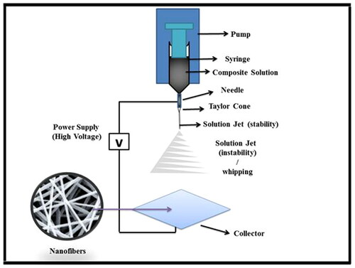
Figure 1. Schematic of a typical electrospinning setup.
Zargham et al. [Citation11] used polyamide 6 and deposited it using an electrospinning method where the angle of the syringe was at a 45° angle with the horizontal baseline. These studies investigated the effect of flow rate on a change in fiber diameter using different flow rates. Pokorný et al. [Citation12] measured the electric current in the plane solution using electrospinning in the deposition area up the vertical (180° from a downward vertical baseline), while changing the pulses using an oscilloscope measurement. The speed of the growth of the discharge channel with other parameters was differentiated by the shape of these pulses.
Bagheri et al. [Citation13] studied the effects of applied electric and magnetic fields through electrospinning using a horizontal setup and a solution of 18% polyamide in formic acid, leading to nanofibers with a smaller diameter than conventional electrospinning. Rodoplu and Mutlu [Citation14] described the effect of vertical versus horizontal electrospinning setups and electrospinning parameters on fiber morphology. Their work aimed at obtaining finer and non-beaded fiber morphologies, by controllable process parameters, for further applications of quartz crystal microbalance (QCM) surfaces in high performance DNA-, immuno-, aptamer-sensor applications [Citation15].
This study observes the effect of gravity on droplets of polymer solution which in turn, affects the morphology as well as fiber diameter and leads to uniform fibers, making it one of the more influential electrospinning parameters [Citation16–18], in addition to other means of changing electrospinning parameters and setups.
2. Experimental
2.1. Preparation of TiO2/PVP nanocomposites
Polyvinylpyrrolidone (PVP) (C6H9NO)x, MW: ∼1,300,000, Sigma Aldrich, USA) was used as precursor solutions. This PVP solution was made by dissolving 0.9 g into 15 mL of ethanol (EtOH, 99.9%). The 7.6 wt% polymer solution was magnetically stirred for 6 h at room temperature (RT). The other solution was made by adding 0.076 g of titanium dioxide (TiO2) to 5 mL of ethanol and this 1.9 wt% TiO2 dispersion was ultrasonically stirred for 30 min. Then, 4.0 mL of the TiO2 solution was transferred to the PVP solution. After that, the mixed solution was stirred overnight at RT. This homogeneous solution (5 mL) was then transferred to a 10 mL plastic syringe (needle 20 gauge). The syringe was placed in a syringe pump with its needle connected to a high voltage power supply, generating a high voltage up to 15 kV. The conditions used to produce the TiO2/PVP nanofibers involved a needle to collector distance of 15 cm, a flow rate of 1 mL/h and a voltage of 14 kV. After electrospinning, the nanofiber mats were removed from the aluminum foil that was used collector.
2.2. Characterizations techniques
Morphological surface observations and structural investigations were performed by field emission scanning electron microscopy (FESEM) using a model FEI Nova NanoSEM 450 (Netherlands) and high resolution X-ray diffractometer (HR-XRD) using a Philips X’Pert system (Netherlands) equipped with Cu-K radiation (0.15419 nm), respectively. Raman spectra were measured at RT using a Horiba Jobin Yvon HR 800 UV (France) spectrometer system with a 514.5 nm Ar+ laser as excitation source. Micro-photoluminescence (m-PL) measurements were carried out at RT using a HeCd laser with an excitation source of 325 nm. Atomic force microscopy (AFM) was performed using a Veeco NanoScope Analysis 1.2 (USA).
2.3. Electrospinning setup
Electric spinning devices are rather simple devices which have three main parts namely a high-voltage power supply, a syringe pump and a collector. Currently, there are basically two electrospinning setups, a vertical and horizontal setup. As shown in , the setup involves a high voltage power supply with an adjustable control up to 15 kV DC, a syringe with a metal needle in the polymer solution which was used to charge the polymer solution, a syringe pump to control the precise flow rate of polymer solution and conductive collector. In this work, electrospinning was performed using several setups. Vertical position was when the needle was pointing toward the ground and the configuration is shown in .
Figure 2. Schematic of the electrospinning setups with different spinning angles.
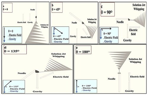
Needle at 0° with the y-axis (vertical setup).
Needle at 45° with the y-axis.
Needle at 90° with the y-axis (horizontal setup).
Needle at 135° with the y-axis.
Needle at 180° with the y-axis (vertical setup).
2.4. Mechanism and working parameters
Polymer was dissolved and turned into a 7.6 wt% polymer solution which was subsequently mixed with TiO2. The solution was transferred to the syringe and electrospinning was carried out with the resulting TiO2/PVP solution used in stages to study spinning parameters. An electric field between the needle and collector plate was created by a high voltage source while the solution was pushed from the syringe by the pump, resulting in a Taylor cone at the needle tip and a controlled flow rate [Citation19]. The power supply caused a surface charge on the solution and the formation of a jet [Citation8], with the solvent evaporating during travel to the collector plate and nanofibers deposited layer-by-layer on the collector plate. The effect on the structural morphology of the nanofibers determined the optimal operating conditions and the appropriate parameters that affect the electrospinning [Citation20].
In this work, the effect of gravity on morphology and fiber diameter was studied, in which electrospinning was carried out at several different angles. The strength of the electric field represents (); the strength of gravity on the droplet mass represents (
).
Needle at 0° with the y-axis: In this situation, a droplet in the middle of the tip of the needle has an aspheric shape influenced by the electric field and gravity at zero angle, where (A, B) are directed toward the ground (i.e. vertically to the bottom) as shown in Thereafter, the surface charge overcomes the surface tension where it expedites the jet to travel to the collector plate while being under the influence of two forces, causing fibers not to stick to each and possess relatively high average diameters. When the droplet was affected by gravity, the strength (
) is calculated by Equation (1) [Citation21].
Needle at 45° with the y-axis: In this situation, a droplet tends to deposit under the influence of gravity. The electric field strength between gravity and 45° angle is shown in . After the surface charge overcomes the surface tension and gravity, the jet moves toward the collector plate with an average diameter previously unseen and wet fibers sticking together. When the droplet was attracted by gravity, the strength (R) is calculated by Equation (2) [Citation21].
Needle at 90° with the y-axis: In this situation, a droplet tends to be affected by the effect of gravity, resulting in a semi-spherical shape. The angle between the strength of the electric field and gravity at 90° is shown in . In this horizontal setup, the jet flies to the collector plate after the surface charge overcomes the surface tension and gravity, forming a non-uniform fiber diameter previously unseen with wet fibers sticking together. When the droplet is attracted by gravity, the strength (R) is calculated by Equation (3) [Citation21].
Needle at 135° with the y-axis: In this situation, a needle points upward and the droplet tends to be affected by gravity to a near oval shape. The angle between the strength of the electric field and gravity for 135° is shown in . After the surface charge overcomes the surface tension and gravity, the jet travels to the collector plate. Fibers form with an average diameter previously unseen that stick together. When the droplet was attracted by gravity, the strength (R) is calculated by Equation (4) [Citation21].
Needle at 180° with the y-axis: In this situation, the droplet tends to move to the bottom due to the influence of gravity with a semi-spherical flat shape. The angle between the strength of the electric field and gravity of 180° (i.e. vertically to the top) is shown in . After the surface charge overcomes the surface tension and gravity the solution jet flies to the collector plate to form fibers with more uniform diameters than the previous cases, which also did not stick together and showed low average fiber diameters. When the droplet was attracted by gravity, the strength (R) is calculated by Equation (5) [Citation21].
As can be noted through the schematic illustrations, instability of the polymer solution jet (whipping) is affected by gravity. Gravity bends the jet toward the ground for the first few moments before the electric field is taking effect by redirecting it to the collector, and an instable jet is shown at an angle of 45°, 90°, and 135°. The electrospinning setup at an angle of 0° will suffer from instability (whipping), spacing circles a little bit through the effect of the gravity. At 180° instability (whipping) occurs unlike that for 0° angle.
3. Results and discussion
3.1. XRD characterization
Crystal analyses of TiO2/PVP thin films, X-ray diffraction (XRD) patterns of the deposited thin films with different deposition angles 0, 45°, 90°, 135°, and 180° are shown in . The films were found to be polycrystalline in tetragonal structure compared with the standard pattern, XRD patterns of TiO2/PVP composite nanofibers, and crystalline peaks corresponding to TiO2 in the form of either anatase, a metastable mineral form of TiO2, or mixed anatase [Citation22–26]. The nanofibers spun at zero to 180° showed a highly pure anatase phase of TiO2 and according to the data of the XRD peaks the lattice parameters of the anatase phase were (a) 3.785 Å and (c) 9.587 Å. Meanwhile, the nanofibers spun at 180° showed anatase and emergence of rutile phase of TiO2. The lattice parameters calculated for the rutile phase were (a) 4.597 Å and (c) 3.154 Å, and were close to standard values. The highest peak in the XRD patterns were observed at ∼25.31° and was related to the A(101) plane for the TiO2 films deposited at 0, 45°, 90°, 135°, and 180°. It can be seen that the film obtained at 180° showed diffraction peak at 25.31° related to the A(101) plane of TiO2/PVP. The deposition angles at 0° and 45° () show five 2θ peaks at 25.31°, 37.77°, 48.05°, 53.92°, and 55.12° and were related to (101), (004), (200), (105), and (211), respectively, with different intensities. A spinning angle of 90° (), shows seven 2θ peaks at 25.31°, 37.77°, 38.63°, 48.05°, 53.92°, 55.12°, and 62.72°, and were related (101), (004), (112), (200), (105), (211), and (204), respectively, with an intensity higher than at 0°, 45° and 135° angles. At an angle of 135° (), six peaks at 2θ were observed at 25.31°, 37.77°, 48.05°, 53.92°, 55.12°, and 62.72° related (101), (004), (200), (105), (211), and (204), respectively with intensities higher than at angles 0° and 45°. Finally, at an angle of 180° (), there are eight 2θ peaks at 25.23°, 37.01°, 37.77°, 38.62°, 48.11°, 53.99°, 55.16°, and 62.71°, which were related (101), (103), (004), (112), (200), (105), (211) and (204), respectively, with an intensity higher than at other angles, suggesting well-crystallined structures compared with other angles. The diffraction peaks are wide and become wider with changing deposition angle.
Figure 3. XRD pattern for TiO2/PVP nanofibers at different deposition angle (a) 0°, (b) 45°, (c) 90°, (d) 135°, (e) 180°.
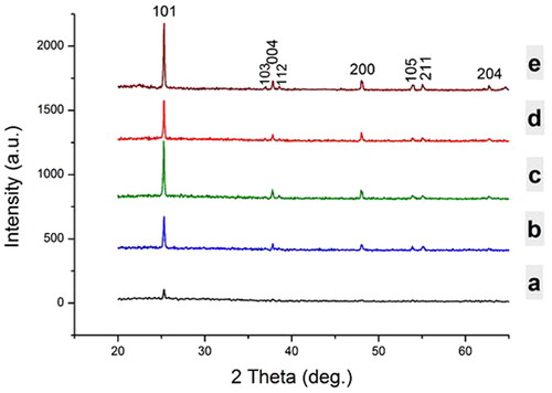
These peak positions correspond well with the JCPDS data for the anatase phase of TiO2.
(6)
(6)
where D is the crystallite size, β is the full width at half maximum (FWHM), λ is the wavelength of X-ray radiation, and θ is the diffraction angle. It was shown that the average grain size increased from 11.04 nm to 68.35 nm with different deposition angles from 0° to 180° (see ). Crystallite size increased and defects were removed when changing the electrospinning setup by varying the deposition angle from 0°, 45°, 90°, 135° to 180°, respectively. Removal of grain borderline defects and increased grain size decreased the strain in this zone [Citation27, Citation28]. The lattice strain is calculated from EquationEquation (7)
(7)
(7) .
(7)
(7)
where
is lattice strain,
and
are for the 0° angle highest lattice strain with the grain size becoming smaller because there are several atoms and defects present at the grain boundaries. These defects and atoms produce a stress field in the nearby region and impose pressure on the system [Citation27]. Where the lattice strain is negative, the system is under a compressive stress [Citation29, Citation30]. It is observed that at an angle of 180° there is less lattice strain where the grain size is larger due to the removal of defects and excess atoms (see ). It is necessary to reduce the surface roughness and dislocation density for the manufacture of high quality thin films for use in optical devices. The dislocation density suggests several flaws and defects in the film of similar size as the average size of the crystals (D) as calculated using the relationship in EquationEquation (8)
(8)
(8) [Citation31], and giving a lower dislocation density at angle 180° as seen in .
(8)
(8)
Table 1. Deposition angle, FWHM value, grain size (D), dislocation density (δ), and texture coefficient (Tc(hkl)) values of TiO2/PVP thin films for (101) plane.
The deposition angle, FWHM value, grain size (D), strain (ε), and dislocation density (δ) values of TiO2 thin film for samples with different deposition angles are listed in . The preferential orientation of the deposited film was at an angle of 180°. It shows that a deposition angle of 180° is better than other angles, decreasing the grain size, increasing the dislocation density, and thus increasing the tension, where these parameters reach saturation values [Citation32].
3.2. FESEM characterization
shows the FESEM images of TiO2/PVP nanofiber mats with different deposition angles of 0°, 45°, 90°, 135°, and 180°. When the angle changes from 0° to 180°, the average diameter of the nanofibers decreases from 128 to 75 nm. The distribution of the diameter of the nanofiber mats is shown in . We observed that changing the deposition angles results in a change in shape of the droplet because of the combined effect of gravity and electric field, causing some changes in fiber morphology. The effect of gravity and electric field on the droplet shape and size led to a higher charge density on the surface of the solution jet during electrospinning. As the charges carried by the jet increase, there are higher protraction forces on the jet under the influence of the electric field. The general tension in the fibers depends on the self-repulsion of the surplus charges on the solution jet, with the fiber diameter decreasing when the charge density increases. Non-uniformity was observed for angles of 45° and 135° (), while at an angle of 90° () the mats appeared semi-uniform. At deposition angles of 0° and 180° (), the mats appeared uniform with nanofibers of smaller diameters. The effect of gravity on the jet and Taylor cone was observed because of the effect of gravity, where it affected mat morphology and fiber diameter. At an angle of 0° () gravity and electric field work in the same direction, resulting in an acceleration of the fabrication of nanofibers because of the impact of forces on the jet. Average fiber diameters were 98 nm and were rather uniform [Citation14].
Figure 4. FESEM image for TiO2/PVP nanofibers at different deposition angles (a) 0°, (b) 45°, (c) 90°, (d) 135°, (e) 180°.
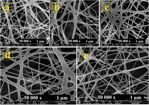
At deposition angles of 45° and 135° (), non-uniformity occurred near the edge of the glass substrate due to the effect of gravity on the jet and Taylor cone. Here, the electric field strength was more effective than gravity in making the jet take another path to the collector plate. This causes elongational instabilities in the solution jet (whipping) due to gravity with average diameters of 122 nm and 128 nm, respectively. At a deposition angle of 90° () both gravity and the electric field cause the acceleration of the jet toward the collector plate, causing the emergence of a semi-uniform mat morphology with an average nanofiber diameter of 118 nm [Citation14]. At an angle of 180° (), gravity and electric field work in opposite directions resulting in enough time for the fabrication of nanofibers because the impact of the forces on the jet appear to be uniform, resulting in an average fiber diameter of 75 nm, i.e. smaller than for other angles. The results of the FESEM images at an angle of 0° and 180° (i.e. vertically to the bottom and to the top) show the biggest effect of gravity, and shows that gravity affects the size and shape of the Taylor cone and the ejected droplet in horizontal and vertical electrospinning setups [Citation14].
4. Conclusions
This work reports a novel approach for altering the morphology of electrospun fiber mats and fiber diameter. The approach involves a simple concept based on changing the deposition angles during electrospinning from 0° to 180°, and revealed an effect of gravity on fiber mat formation and fiber diameter. This study showed that gravity has two effects: one negative and one positive depending on disposition angle. This work opens some new prospects for the design of electrospun fiber mats with better controlled morphologies and appropriate levels of solvent evaporation.
Disclosure statement
No potential conflict of interest was reported by the author(s).
Additional information
Funding
Notes on contributors
Nabeel Z. Al-Hazeem
Nabeel Z. Al-Hazeem, master of nanotechnology from School of Physics, Universiti Sains Malaysia. Nabeel does research in Applied Mathematics, Solid State Physics, and Nanotechnology, A specialty is ‘Electrospinning for applications of sensores and solar cells. Nabeel teacher of physics in Gifted Students School in Anbar, Iraq. He currently PhD student in Institute of Nano-Optoelectronics Research and Technology (iNOR)-Malaysia. He has 12 publications that have been cited 37 times and has shared a chapter in book around 2000 download with citation 13 times, his publication H-index is 4 and has been service as a reviewer of reputed Journals in IOP and Springer.
Naser M. Ahmed
Dr. Naser Mahmoud Ahmed received his B.Sc. degree 1984 in Physics from Almustansiriah University, M.Sc. laser technology 1988 from University of technology, Iraq and PhD from Universiti Sains Malaysia, Malaysia, in 2006. Presently, working Senior lecturer in School of Physics, Universiti Sains Malaysia. He is the author/co-author of more than 310 research papers published in international journals, two patent and is the author of 6 books. His current research interests in laser design, laser ablation, LED, Nanorods, pH sensor, quantum dots and photodetector.
M. Z. Mat Jafri
Mohd. Zubir Mat Jafri is a lecturer and researcher at the School of Physics, Universiti Sains Malaysia. He obtained his B.Sc. (1984) with first class honours in Physics from Universiti Kebangsaan Malaysia, M.Sc. (1991) in Microprocessor Technology and Applications from Brighton Polytechnic, UK, and his Ph.D. (1996) from University College of Swansea, Wales, UK, focussing on algorithms development for detecting curves from digital images using Hough Transform. He has more than thirty years teaching experience in the area of physics, optical communication, digital image processing, digital and analogue electronics and also microprocessor. His research interest includes the area of microprocessor-based system, automation visual inspection system, nonlinear optics, optical sensor, digital image processing and remote sensing. He has published five books and more than three hundred articles in those areas in national and international proceedings and journals. He is a life member of Malaysian Institute of Physics and member of International Society for Optical Engineering (SPIE), IEEE, WWF Malaysia since 2004, and Member of National Geographic since 1999. He was also an associate of IEE UK 1993–1996.
Asmiet Ramizy
Prof. Dr. Asmiet Ramizy, received M.Sc. degree in Physics from Mustansiriyah University - college of science, Iraq 1999, and Ph.D. degree in 2011 from Universiti Sains Malaysia, Academic staff at University of Anbar Iraq, since 2001. Editor boarding in ISI journals. He has published 80 papers in ISI journals and 20 in non-ISI journals. Participated in many national, international conferences, and workshops. Research interested in nanostructured materials and their applications, Laser-Induced Etching and porous solar cell.
References
- Zhang X, Shi X, Gautrot JE, et al. Nanoengineered electrospun fibers and their biomedical applications: a review. Nanocomposites. 2021;7(1):1–34.
- Fridrikh SV, Jian HY, Brenner MP, et al. Controlling the fiber diameter during electrospinning. Phys Rev Lett. 2003;90(14):144502.
- Al-Hazeem NZA. Nanofibers and Electrospinning Method. Nov Nanomater Synth Appl. 2018;191–210.
- Patra S, Easteal A, Bhattacharyya D. Parametric study of manufacturing poly (lactic) acid nanofibrous mat by electrospinning. J Mater Sci. 2009;44(2):647–654.
- Li D, Wang Y, Xia Y. Electrospinning of polymeric and ceramic nanofibers as uniaxially aligned arrays. Nano Lett. 2003;3(8):1167–1171.
- Kumar A, Jose R, Fujihara K, et al. Structural and optical properties of electrospun TiO2 nanofibers. Chem Mater. 2007;19(26):6536–6542.
- Wu CM, Chiou HG, Lin SL, et al. Effects of electrostatic polarity and the types of electrical charging on electrospinning behavior. J Appl Polym Sci. 2012;126(S2):E89–E97.
- Taylor G. Disintegration of water drops in an electric field. Proc R Soc Lond A: Math Phys Eng Sci. 1964;280(1382):383–397.
- Al-Hazeem NZ, Ahmed NM. Effect of addition of polyaniline on polyethylene oxide and polyvinyl alcohol for the fabrication of nanorods. ACS Omega. 2020;5(35):22389–22394.
- Bhardwaj N, Kundu SC. Electrospinning: a fascinating fiber fabrication technique. Biotechnol Adv. 2010;28(3):325–347.
- Zargham S, Bazgir S, Tavakoli A, et al. The effect of flow rate on morphology and deposition area of electrospun nylon 6 nanofiber. J Eng Fibers Fabr. 2012;7(4):42–49.
- Pokorný P, Mikes P, Lukas D. Measurement of electric current in liquid jet. Proceedings of the Nanocon International Conference; 2010. p. 12–14.
- Bagheri H, Piri-Moghadam H, Rastegar S. Magnetic and electric field assisted electrospun polyamide nanofibers for on-line μ-solid phase extraction and HPLC. RSC Adv. 2014;4(94):52590–52597.
- Rodoplu D, Mutlu M. Effects of electrospinning setup and process parameters on nanofiber morphology intended for the modification of quartz crystal microbalance surfaces. J Eng Fibers Fabr. 2012;7(2):118–123.
- Al-Hazeem NZ, Ahmed NM, Matjafri M, et al. Hydrogen gas sensor based on nanofibers TiO2-PVP thin film at room temperature prepared by electrospinning. Microsyst Technol. 2021;27(1):293–297.
- Erisken C, Kalyon DM, Wang H. Functionally graded electrospun polycaprolactone and beta-tricalcium phosphate nanocomposites for tissue engineering applications. Biomaterials. 2008;29(30):4065–4073.
- Sangsanoh P, Suwantong O, Neamnark A, et al. In vitro biocompatibility of electrospun and solvent-cast chitosan substrata towards Schwann, osteoblast, keratinocyte and fibroblast cells. Eur Polym J. 2010;46(3):428–440.
- Charernsriwilaiwat N, Opanasopit P, Rojanarata T, et al. Preparation and characterization of chitosan-hydroxybenzotriazole/polyvinyl alcohol blend nanofibers by the electrospinning technique. Carbohydr Polym. 2010;81(3):675–680.
- Taylor G. Electrically driven jets. Proc R Soc Lond A: Math Phys Eng Sci. 1969;313(515):453–475.
- Doshi J, Reneker DH. Electrospinning process and applications of electrospun fibers. Conference Record of the 1993 IEEE Industry Applications Society Annual Meeting, 1993; IEEE; 1993. p. 1698–1703.
- Marsden JE, Tromba A. Vector calculus. London: Macmillan; 2003.
- Ma W, Lu Z, Zhang M. Investigation of structural transformations in nanophase titanium dioxide by Raman spectroscopy. Appl Phys A. 1998;66(6):621–627.
- Arbiol J, Cerda J, Dezanneau G, et al. Effects of Nb doping on the TiO2 anatase-to-rutile phase transition. J Appl Phys. 2002;92(2):853–861.
- Ruiz AM, Dezanneau G, Arbiol J, et al. Insights into the structural and chemical modifications of Nb additive on TiO2 nanoparticles. Chem Mater. 2004;16(5):862–871.
- Suresh C, Biju V, Mukundan P, et al. Anatase to rutile transformation in sol-gel titania by modification of precursor. Polyhedron. 1998;17(18):3131–3135.
- Gao Y, Masuda Y, Seo W-S, et al. TiO2 nanoparticles prepared using an aqueous peroxotitanate solution. Ceram Int. 2004;30(7):1365–1368.
- Qin W, Szpunar J. Origin of lattice strain in nanocrystalline materials. Philos Mag Lett. 2005;85(12):649–656.
- Moghaddam HM, Nasirian S. Dependence of activation energy and lattice strain on TiO2 nanoparticles? Nanosci Methods. 2012;1(1):201–212.
- Croft M, Zhong Z, Jisrawi N, et al. Strain profiling of fatigue crack overload effects using energy dispersive X-ray diffraction. Int J Fatigue. 2005;27(10–12):1408–1419.
- Ghosh P, Oliva J, Rosa E.D., et al. Enhancement of upconversion emission of LaPO4: Er@Yb core–shell nanoparticles/nanorods. J Phys Chem C. 2008;112(26):9650–9658.
- Williamson G, Smallman R, III. Dislocation densities in some annealed and cold-worked metals from measurements on the X-ray Debye-Scherrer spectrum. Philos Mag. 1956;1(1):34–46.
- Chinh NQ, Gubicza J, Langdon T. Characteristics of face-centered cubic metals processed by equal-channel angular pressing. J Mater Sci. 2007;42(5):1594–1605.