
Abstract
This paper describes the experimental investigation in the drilling of glass fiber reinforced polymer (GFRP) composites with three dissimilar tools, having different materials and geometries (i.e. helical flute (HSS) drill, Carbide tipped straight shank (K20) drill, and Solid carbide eight-facet drill). Tool geometry and materials are considered to be major factor, which is responsible for drilling-induced damage. Cutting parameters also influence drilling-induced damage. These damages were measured by two delamination factors. Image processed technique was utilized to determine the damaged area and maximum damaged zone diameter. The results showed that qualities of drill holes significantly improved when solid carbide eight-facet drill was used.
Introduction
Nowadays, glass fiber reinforced polymer (GFRPs) composite materials are extensively used in aeronautics, sporting goods, domestic sector, railway, energy field and automobiles due to their low weight and high aspect ratio. Parts and components made of GFRPs need certain machining operations, such as, milling, grinding, and drilling for the purpose of fastening, where it is used, Grilo et al.Citation1 The most suitable and widely acceptable machining operation is the traditional drilling method. This process is employed for creating hole in the composite materials. During drilling operation, different sorts of damage may occur such as, cracking of matrix, pull-out of fibers, breakage of fiber, and drilling-induced damage, i.e. delamination. It happens due to the separation of layers of the materials, Karimi et al.Citation2
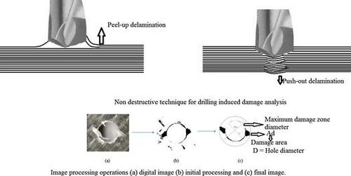
As a result of the damage, mechanical strength of the parts reduces. It has been found that in aerospace industries, nearly 60% of the components are rejected owing to drilling-induced damages. Delamination due to drilling takes place on both sides of the specimen, (i.e. entrance and exit). Investigations have revealed that two obvious mechanisms of delamination are peel-up and push-out of fibers, Liu et al.Citation3 Push-out delamination is more drastic as compared to the peel-up delamination. Major financial losses, caused due to drilling-induced delamination, which have driven researchers to make repeated attempts for devising ways to minimize this damage and enhance the machining parameters. They have also working on the development of a new geometry of cutting tool to improve the machining quality.
Cutting tool materials and geometry play an important role in the delamination process, Abrao et al.Citation4 According to Piquet et al.Citation5 when drilling CFRP laminates with different drill bits, delamination can be kept minimum due to less touching length between drill and hole. Davim and RiesCitation6 carried out an experiment on drilling of CFRP having thickness of 4 mm, with dissimilar drills of different materials and having different geometry. The drill had a diameter of 5 mm and point angle at 118°. They have found that minimum delamination occurred when tungsten carbide drill was used. Singh and BhatnagarCitation7 studied major effects of geometry on drills. Their investigation confirmed that drilling-induced damages are minimum when using eight facets and jo drills. Cutting parameters also play a vital role in the variation of cutting forces, irrespective of damages during the process of drilling, Chen.Citation8 Damages do not occur when drilling GFRP at low feed rate. However, when feed rates are augmented, the back rake angle becomes negative. As a result, the workpiece gets pushed without shearing and hence delamination occurs, Capello.Citation9 When drilling woven glass/epoxy composite, delamination at both sides of the work piece material decreases because as cutting speed increases, Khashaba.Citation10 According to Rajamurugan et al.Citation11, when drilling glass fiber/polyester composite materials, delamination increases with an increase in the feed rate. While increasing the cutting speed, delamination decreases moderately. However, appropriate selection of cutting parameters ensures less damage in the drilling of GFR-Polyester composite material. Marques et al.Citation12 investigated drilling of CFRP materials with varying feed and spindle speed. They have found that due to increase in feed rate delamination around the hole increases. The best result was obtained on a low feed rate of 0.025 mm/rev. Kumar and SinghCitation13 studied the drilling of composite materials and found that when feed rate increases, delamination also increases on both sides of the holes. Hocheng and TsaoCitation14 studied about drilling-induced damage of composite materials using special drill bits. The results showed that delamination was the least at lower thrust force for every drill bits. Moreover, thrust force reduced when feed rate (2 × 10⁻³ mm/rev) was low.
In the machining operation, surface finish is a significant factor. Roughness of the machined surface is the focus of many studies. Surface finish is a significant design quality and a determining factor in precision fit, fastener load, and fatigue load. In addition to tolerance, proper selection of the cutting parameter is a significant prerequisite for control of surface roughness. Feng and Feng.Citation15 Feed rate and spindle speed also play an important role in surface roughness. When the feed rate is 0.10 mm/rev, surface roughness is high at a low cutting speed. However, surface roughness decreases when cutting speed goes up, Palanikumar et al.Citation16 Latha and SenthilkumarCitation17 investigated surface roughness in the drilling of GFRP composites. They have found that the feed rate and drill diameters have significant influence on surface roughness. When feed rate increases, there is a major rise in surface roughness, whereas changing the diameter of drills, result indicates slight changes in the surface roughness. For instance, with 6 mm drill diameter, surface roughness values vary from 1.6502 to 3.5373 μm. According to Palanikumar, et al.Citation18, surface roughness depends upon cutting parameters and drill diameter. Surface roughness increases with an increase in the feed rate. Again, surface roughness is minimum when small drill diameter is used. Spindle speed, on its part, has modest influence on the drilling of GFRP. Takeyama and LijimaCitation19 found that when glass fiber-reinforced plastics are used for machining operation, surface roughness is minimum at high cutting speed. In the process, cutting temperature becomes high, leading to the softening of the work material. According to Palanikumar,Citation20 when machining GFRP, it is difficult to simultaneously reduce thrust force, surface roughness, and delamination. However, by utilizing the average grey relation, he found that at 100 mm/min feed rate and 2500 rpm, thrust force, surface roughness and delamination could be kept low with the value of surface roughness varying from 2.07 to 8.11 μm.
Most of the studies on machining of GFRP composite materials illustrate delamination and surface roughness as important parameters that have to be kept at a minimum level. Many researchers worked on drilling operation using different types of drill bits with different machining parameters. Among these, the most favorable conditions were found to be low feed rate and high spindle speed. In the present study, an experiment was carried out on the drilling of plain woven GFRP composite materials, using three dissimilar drill bits of different materials and geometries. The main factor in consideration was different tool materials, drill geometry and process parameters. Delamination factors and surface roughness were studied at different spindle speeds and feed rates.
Experimental technique
Measurement of delamination
The widely used procedure to enumerate delamination, depends on the delamination factor. For determining delamination at both sides of the work piece, these factors are employed. According to Bosco et al.,Citation21 delamination factor is calculated using the expression:(1)
where the damaged zone diameter is indicated by Dmax and D indicate the diameter of hole as presented in Figure . However, in this equation, the damaged area is not indicated. Thus, this may not suitably indicate the damaged magnitude during the machining process of the materials. Shyha and AspinwallCitation22 used another relation to signify the damaged area, which is expressed as:(2)
Figure 1 Image processing operations a digital image b initial processing and c final image

where(3)
Here, A is the area of the hole, D denotes the diameter of the hole, Ad is the damaged area, Amax is the area of the damaged zone, Dmax is the maximum damaged zone diameter, Fd is the conventional delamination factor, Fda is the adjusted delamination factor, and α is the weight of the conventional delamination factor.
These factors can be interpreted as the ratio of the damaged area (Ad) to the drilled hole area (A), Mohan et al.Citation23 However, both the delamination factor (Fd) and the adjusted delamination factor (Fda) can be taken into account to determine the delamination.
Workpiece material and tools
The GFRP workpiece material was prepared by the vacuum bagging method. An asymmetric laminate of GFRP was prepared using eight layers of the plain woven glass fiber of stacking order (0, 90/±45/±45/0, 90/±45/0, 90/0, 90/±45) with 49% of fiber volume fraction. The details of the mechanical assets of matrix, fiber and hardener are given in Table . The resin and hardener were supplied by Atul Industries Ltd., Gujarat, India. Laminates of 200 × 200 mm were prepared with 3.78 mm thickness. Specimens for drilling were cut into 30 × 90 mm and both sides of the drilled holes were studied.
Table 1 Mechanical properties of fiber, resin, and hardener
All tests were carried out with conventional drilling machine that had a maximum spindle speed of 2000 rpm. Three drills were used having different geometries and materials, namely, a helical flute (HSS) drill, carbon tipped straight shank (K20) drill and solid carbide eight-facet drill. Table summarizes the geometrical dimensions of the drill used in the experiment.
Table 2 Drill geometries
For preventing vibration and displacements during the drilling process, the GFRP plates were held in place with a scheme of clamps. The tested drills are represented in Figure . The images of the holes were taken by a digital scanner. Next, the maximum damaged zone diameters and damaged area were measured using an image processing software. Surface roughness (Ra) was measured using Surftest SJ-210, manufactured by Mitutoyo America. It complies with ISO 1997 standard and has a moving speed 0.5 mm/s. Ra could be used as a parameter for detecting internal workpiece delamination as deep valleys were typically observed at the damage location.
Figure 2 Tested drills a Helical flute (HSS) drill b Carbide tipped straight shank (K20) drill c Solid carbide eight-facet drill
Plan of experimental tests
The drilling of an asymmetric laminates of GFRP was carried out by Batliboi BVR5 radial drilling machine, whose spindle power is 8 kW and have a maximum speed of 2000 rpm. Parameters that affect the drilling process are spindle speed and feed rate, respectively. Experiments are conducted according to parameters described in Table . For every experiment, new drill has been used to drill in workpiece at different feed rate and spindle speed. Then, the work piece was scanned using 600 dpi-resolution scanner. The scanned image was used for analysis of damages around the hole. Using image J 1.46 software, Ponnuvel and MoorthyCitation24 analyzed the entrance and the exit side of the holes with proper brightness/contrast, color threshold, noise, and binary. The maximum damaged zone diameter and delaminated area are measured using image J 1.46r software at both sides of the holes as shown in Tables . For the measurement of surface roughness, Surftest-210 machine was used. Surface roughness has been measured at four different section of hole, then average of these measurement were taken for surface roughness analysis.
Table 3 Machining parameters
Table 4 Results for solid carbide eight-facet drills entrance of hole
Table 5 Results for solid carbide eight-facet drills exit of hole
Table 6 Results for carbide tipped straight shank (K20) drills entrance of hole
Table 7 Results for carbide tipped straight shank (K20) drills exit of hole
Table 8 Results for helical flute (HSS) drills entrance of hole
Table 9 Results for helical flute (HSS) drills exit of hole
Results
The figure demarcating the delaminated area in dark represents the processed image of each hole. Fda and Fd were calculated for each hole. Tables and indicate the quality of the holes drilled, when solid carbide eight facet drill was used with different cutting parameters. Similarly, Tables and represent the results when carbide tipped-straight shank (K20) drill was used. Tables and explain the results of the helical flute (HSS) drill used with different cutting parameters.
The values of delamination factor and adjusted delamination factor for all drills have been compared in Figures . It reveals that drilling-induced damage (i.e. delamination) depends on machining parameters as well as materials and geometry of the drills. As feed rate increases, damage around the hole increases, however, at higher spindle speed, lower delamination was measured. Surface roughness of hole was measured at given cutting parameters. It has been found that at higher spindle speed surface roughness is minimum. Surface quality of the hole significantly improves using solid carbide eight facet drill. For each hole, three measurements were taken and the average values are listed in Table . Comparison of the results of surface roughness in drills has been presented in Figure .
Figure 3a Delamination and adjusted delamination factor of solid carbide eight-facet drill at entrance
Figure 3b Delamination and adjusted delamination factor of solid carbide eight-facet drill at exit
Figure 4a Delamination and adjusted delamination factor of carbide tipped drill at entrance
Figure 4b Delamination and adjusted delamination factor of carbide tipped drill at exit
Figure 5a Delamination and adjusted delamination factor of helical flute (HSS) drill at entrance
Figure 5b Delamination and adjusted delamination factor of helical flute (HSS) drill at exit
Table 10 Surface roughness values of tested drills
Figure 6 Surface roughness of tested drill

It is essential to point out that the linear relationship between the points in the graphs may not depict the interpolated values; though it is utilized for better appreciation and evaluation of the results.
Discussion
Analysis of delamination
Drilling of GFRP composite materials is essential in the manufacturing industries. Drilling of GFRP composite materials are different from other materials. Two basic factors (cutting parameters and drills having dissimilar materials and geometry) need to be analyzed to determine their effect on damages around the holes. Drills with different geometries act differently in the drilling of GFRP composite material. The cracks between the plies in the drill component develop due to delamination, this may ruin the mechanical performance. The values of delamination, adjusted delamination and delaminated area were calculated, using figures denoted in Tables . The results indicate that due to the relation of Fda given in [Eq. (Equation3(3) )], the delamination factor is always less than the adjusted delamination factor. From the results, it was found that the geometry of drill and materials has a significant role in the delamination and surface roughness with variation in the spindle speed and feed rate. There are two obvious mechanisms of delamination in the drilling of GFRP composite materials i.e. peel-up and push-out. The cutting edge of the drill grazes the laminate when the drill bit touches the work piece. The grazed material gets pulled along the flute and spirals up. As a result, the upper lamina peels up and causes peel-up delamination. At the exit, the uncut plies bend elastically due to the compressive force exerted by drills. When the drill approaches the exit, resistance to the bending decreases due to reduction of pressure on the uncut plies. Next, as bending stress increases, then the inter-laminar strength of plies weaker, due to this reason, cracks developed around the hole. When the drill point pushes down further, it causes the crack to propagate and the flexural rigidity of plies becomes weaker. As a result, the inter-lamina bonding failure produces push-out delamination.
In case of solid carbide eight-facet drill, it has been noticed that when the feed rate increases from 0.02 rev/mm to 0.10 mm/rev, delamination factors increase as well as shown in Figure . As the feed rates are high, the failure mode shows feature of impact damage. However, when spindle speed increases, the delamination factor decreases. It can be observed that at 1500 rpm, delamination decreases because of the solid carbide eight-facet drill that has four cutting edges, and, for every cutting edge, there are two facets. These facets consist of lip clearance angle and lip relief angle but they have no chisel length. As a result, when the drill comes close to the laminates, then only the point contact takes place rather than the surface contact. Because of this point contact, there is load concentration at one point only, which, in turn, causes less damage. The same sequence follows at the exit side of the drill as well. From Figure b, delamination at the exit side can be seen to be minimum compared to the entrance of the drill at 1500 rpm and 0.02 mm/rev.
Results related to the carbide tipped drills (entrance side) show that at low speed, delamination factors are the maximum, but, when the speed increases, delamination factors decrease linearly as shown in Figure a. However, when the feed rate increases, the delamination factor also increases. Carbide tipped drills have two facets for cutting and also have a chisel edge that makes the surface contact with the laminate. As the surface contact load concentration increases, the damage around the hole increases as well. At 0.02 mm/rev, delamination is the maximum. At the exit side, delamination factor is greater than that of the solid carbide drill. However, at 1500 rpm and 0.02 mm/rev, a slight difference can be noticed in delamination factor as shown in Figure b. But in case of the helical flute (HSS) drill, results do not follow any sequence. Delamination factors are low at a low speed and low feed rate. At 800 rpm and 0.02 mm/rev, the adjusted delamination factor is greater due to an increase in the damaged area around the hole as shown in Figure a. The HSS drill has the maximum chisel edge which increases load on the laminate. As the feed rate increases, impact damage at 0.10 mm/rev is the maximum at the entrance of the drill. At the exit of the drill, delamination factor and adjusted delamination factor are greater at 0.02 mm/rev and 1500 rpm, consequent to the use of solid carbide and carbide tipped drill.
Analysis of surface roughness
After the drilling operation, most of the researchers focus on the aspect of surface roughness of the drilled holes. The surface roughness has a very important role in many areas of the machining precision. Many factors, such as, spindle speed, feed rate and depth of cut affect the surface roughness of a given work piece. Moreover, at a lower feed rate and higher cutting speed, the fracture is less aggressive and easier to deal with due to a lower strain rate. Thus, to ensure finer surface roughness, the feed rate is recommended to be set low.
Three drills are used on the GFRP composite materials. From the results of the experiments, it could be observed that the surface roughness at a feed rate of 0.10 mm/ rev was higher than that at a feed rate 0.02 mm/rev, using solid carbide eight-facet drill, the results showed that qualities of the drilled hole surface finishing enhanced appreciably at a higher spindle speed. The results are described in Table . Surface roughness of the hole using the HSS drill and carbide tipped (K20) drill is higher than that of the hole drilled with solid carbide eight-facet drill. The reason for poor surface finish in case of the former is that these two drills may alternately encounter resin and fiber in GFRP specimens. Comparisons of surface roughness results are shown in Figure .
Figure shows FESEM (Field Emission Scanned Electron Micrograph) photographs of hole wall, drilled in woven GFRP composites using solid carbide drill, carbide tipped drill, and HSS drill. The drilling conditions are: spindle speed 1500 rpm and feed rate 0.02 mm/rev. Figure a shows the surface of the hole, drilled by solid carbide drill. One can observe that both the matrix and the fiber are sheared. However, matrix pull-out and uncut fibers are less in number. On the other hand, due to the generation of heat in drilling, the matrix materials are transformed into lumped masses along with the fibers. Figure b illustrates the image of a hole drilled by carbide tipped drill and tiny particles of fiber, which are attached to the upper surface of the hole. Hence, surface roughness of the hole increases. Figure c shows the photograph of a drilled hole using a HSS drill. It can be seen that the fiber and the resin in the composite specimen are removed through the drilling process and the available surface is a coarse structure. From these figures, one could conclude that better surface of hole could be obtained using solid carbide drill at a high spindle speed and low feed rate.
Figure 7 FESEM image of hole drilled at 1500 rpm and 0.02 mm/rev using, respectively, solid carbide drill, carbide tipped drill, and HSS drill
Conclusions
For the damage analysis of GFRP composite materials, both delamination and adjusted delamination factors were calculated.
| • | Higher delamination factor, adjusted delamination factor, and surface roughness values were recorded for the helical flute HSS drill. Therefore, this drill is not recommended for asymmetric laminates of GFRP composites. Its surface roughness values vary from 1.226 to 3.591 μm. | ||||
| • | The delamination factor and adjusted delamination factor are lower for solid carbide eight-facet drill compared to the other two geometries at 1500 rpm and 0.02 mm/rev. | ||||
| • | Surface roughness values of solid carbide eight-facet drill are lower than that of the other two drills used. Surface roughness values vary from 0.384 to 2.227 μm. Hence, solid carbide eight-facet drill is recommended for drilling of asymmetric laminate of GFRP composites. | ||||
| • | Carbide tipped straight shank (K20) drill can be used for drilling asymmetric laminates of GFRP composites because it has the ability to dissipate heat rapidly. But its delamination factor, adjusted delamination factor and surface roughness values are more than the solid carbide eight-facet drills. Surface roughness values vary from 0.794 to 2.769 μm. | ||||
Disclosure statement
No potential conflict of interest was reported by the authors.
References
- T. J. Grilo, R. M. F. Paulo, C. R. M. Silva and J. P. Davim: ‘Experimental delamination analyses of CFRPs using different drill geometries’, Composite: Part B, 2013, 45, 1344–1350.10.1016/j.compositesb.2012.07.057
- N. Z. Zarif Karimi, H. Heidary, G. Minak and M. Ahmadi: ‘Effect of the drilling process on the compression behavior of glass/epoxy laminates’, Compos. struct., 2013, 98, 59–68.10.1016/j.compstruct.2012.10.044
- D. Liu, Y. Tang and W. L. Cong: ‘A review of mechanical drilling for composite laminates’, Compos. Struct., 2012, 94, 1265–1279.10.1016/j.compstruct.2011.11.024
- A. M. Abrão, P. E. Faria, J. C. Campos Rubio, P. Reis and J. P. Davim: ‘Drilling of fibre reinforced plastics: A review’, J. Mater. Process. Technol., 2007, 186, 1–7.10.1016/j.jmatprotec.2006.11.146
- R. Piquet, B. Ferret, F. Lachaud and P. Swider: ‘Experimental analysis of drilling damage in thin carbon/epoxy plate using special drills’, Composites Part A, 2000, 31, (10), 1107–1115.10.1016/S1359-835X(00)00069-5
- J. P. Davim and P. Reis: ‘Study of delamination in drilling carbon fiber reinforced plastics (CFRP) using design experiments’, Compos. struct., 2003, 59, (4), 481–487.10.1016/S0263-8223(02)00257-X
- I. Singh and N. Bhatnagar: ‘Drilling of uni-directional glass fiber reinforced plastic (UD-GFRP) composite laminates’, Int. J. Adv. Manuf. Technol., 2006, 27, 870–876.10.1007/s00170-004-2280-7
- W. Chen: ‘Some experimental investigations in the drilling of carbon fibre reinforced plastics (CFRP) composite laminates’, Int. J. Mach. Tools Manuf., 1997, 37, (8), 1097–1108.
- E. Capello: ‘Workpiece damping and its effect on delamination damage in drilling thin composite laminates’, J. Mater. Process Technol., 2004, 148, (2), 186–195.10.1016/S0924-0136(03)00812-4
- U. A. Khashaba: ‘Delamination in drilling GFR-thermoset composites’, Compos. Struct., 2004, 63, 313–327.10.1016/S0263-8223(03)00180-6
- T. V. Rajamurugan, K. Shanmugam and K. Palanikumar: ‘Analysis of delamination in drilling glass fiber reinforced polyester composites’, Mater. Des., 2013, 45, 80–87.10.1016/j.matdes.2012.08.047
- T. A. Marques, M. L. Durão, G. A. Magalhães, F. J. Silva, R. S. Tavares and J. Manuel: ‘Delamination analysis of carbon fibre reinforced laminates: Evaluation of a special step drill’, Compos. Sci. Technol., 2013, 69, 2376–2382.
- D. Kumar and K. K. Singh: ‘An approach towards damage free machining of CFRP and GFRP composite material: a review’, Adv. Compos. Mater., 2015, 24, (1), 49–63.
- H. Hocheng and C. C. Tsao: ‘Effect of special drill bits on drilling-induced delamination of composite materials’, Int. J. Mach. Tools Manuf., 2006, 46, 1403–1416.
- C. X. Feng and W. X. Feng: ‘Development of empherical models for surface roughness prediction in finish turning’, Int. J. Adv. Manuf. Technol., 2013, 20, (5), 348–356.
- K. Palanikumar, L. Karunamoorthy and R. Karthikeyan: ‘Assessment of factors influencing surface roughness on the machining of glass fiber-reinforced polymer composites’, Mater. Des., 2006, 27, 862–871.10.1016/j.matdes.2005.03.011
- B. Latha and V. S. Senthilkumar: ‘Modeling and analysis of surface roughness parameters in drilling GFRP composite using fuzzy logic’, Mater. Manuf. processes, 2013, 25, 817–827.
- K. Palanikumar, B. Latha, V. S. Senthilkumar and J. P. Davim: ‘Analysis on drilling of glass fiber–reinforced polymer (GFRP) composites using grey relational analysis’, Mater. Manuf. Processes, 2012, 27, 297–305.10.1080/10426914.2011.577865
- H. Takeyama and N. Iijima: ‘Machinability of glassfiber reinforced plastics and application of ultrasonic machining’, CIRP Ann. – Manuf. Technol., 1988, 37, (1), 93–96.10.1016/S0007-8506(07)61593-5
- K. Palanikumar: ‘Experimental investigation and optimisation in drilling of GFRP composites’, Measurement, 2011, 44, 2138–2148.10.1016/j.measurement.2011.07.023
- M. A. J. Bosco, K. Palanikumar, B. D. Prasad and A. Velayudham: ‘Influence of machining parameters on delamination in drilling of GFRP-armour steel sandwich composites’, Procedia Eng., 2013, 51, 758–763.10.1016/j.proeng.2013.01.108
- I. S. Shyha, D. K. Aspinwall, S. L. Soo and S. Bradley: ‘Drilling geometry and operating effects when cutting small diameters holes in CFRP’, Int. J. Mach. Tools Manuf., 2009, 49, 1008–1014.
- N. S. Mohan, S. M. Kulkarni and A. Ramachandra: ‘Delamination analysis in drilling process of glass fiber reinforced plastic (GFRP) composite materials’, J. Mater. Process. Technol., 2007, 186, 265–271.10.1016/j.jmatprotec.2006.12.043
- S. Ponnuvel and T. V. Moorthy: ‘Investigation on the influence of multi walled carbon nanotubes on delamination in drilling epoxy/glass fabric polymeric nanocomposite’, Procedia Eng., 2013, 51, 735–744.10.1016/j.proeng.2013.01.105