
Abstract
Common issues in 3D printed concrete arise due to its high cement content, processing requirements, and the lack of extensive research into its long-term performance. To this end, this study explores using supplementary cementitious materials from local regions to partially replace cement, aiming at reducing the carbon footprint. Various printable mixtures with different substitution rates are formulated, and corresponding mechanical and permeability tests are conducted. It is revealed that the compressive and flexural strengths of 3D printed concrete with low cement content were lower than the strength of cast concrete due to the construction process of printed concrete; the mechanical strength of 3D printed concrete showed prominent anisotropic characteristics. It was found that, compared with the other two sets of ratios, the higher contents of FA and GGBFS could effectively fill the pores of the printed concrete. Both the capillary water absorption and the content of chloride ions of the low-carbon mixture were significantly lower than that of the pure cement-printed specimens.
1. Introduction
The digital fabrication of concrete has developed rapidly in recent years, notably through additive manufacturing methods represented by 3D concrete printing (3DCP) [Citation1,Citation2]. Compared to traditional mold casting processes, the 3DCP technology possesses the advantages of a fast construction pace, low cost, and minimal labor consumption [Citation3–5]. The materials should be easily extruded from the printed head and self-supported after being extruded [Citation6–8]. A high cement content and reduced aggregate sizes are commonly adopted to meet the processing requirements, increasing the amount of carbon emission to a large extent [Citation9,Citation10]. Moreover, the high cement content results in high shrinkage, cracking, and other durability concerns for the 3D-printed concrete elements [Citation11,Citation12].
To improve the sustainability of 3DCP, some researchers are exploring the incorporation of coarse aggregates and augmenting their volume [Citation13]. Additionally, they’re investigating using recycled materials like recycled concrete and glass as a novel approach to address the inadequate environmental friendliness of 3DCP [Citation14,Citation15]. Although the amount of binder is somewhat decreased by those methods mentioned above, using coarse aggregates may cause blockage problems in processing [Citation16]. Alternatively, industrial wastes such as fly ash (FA) [Citation17,Citation18], silica fume (SF) [Citation19,Citation20], and ground granulated blast furnace slag (GGBFS) [Citation21,Citation22] are used to reduce the amount of cement in 3DCP to reduce its carbon footprint [Citation12,Citation23,Citation24].
In terms of mechanical properties, the construction process of 3DCP stacked layer by layer is prone to defects in the bonding interface between layers, resulting in low mechanical properties of the hardened printed components compared to cast-in-place concrete and, at the same time, presenting obvious anisotropy in mechanical strength. Le et al. [Citation25] concluded that the anisotropy of mechanical strength of printed concrete in different loading directions is due to the laminated structure of the printed members. They found that the lowest values of compressive strength of the members under loading along the direction of printing and that the interlayer bonding properties are the main factors affecting the strength. Lee et al. [Citation26,Citation27] studied similar test results. Ma et al. [Citation28] investigated the effect of copper tailings and fibers on the compressive and flexural strength of 3D printed cementitious materials, and the experimental results were consistent with the conclusions of Le et al.’s description of the anisotropy of the printed specimens; it was pointed out that the directional arrangement of the fibers would have a significant effect on the mechanical anisotropy. Panda et al. and Paul et al. [Citation8,Citation29] put forward the viewpoint that the anisotropy of the mechanical strength is an inherent 3D printed concrete property and found that in addition to the printing direction affecting the development of mechanical strength, the shape of the printing nozzle, the extrusion rate, and the complexity of the printed component all affect the development of mechanical strength after hardening. Currently, researchers have focused on the basic mechanical properties of 3D printed concrete after hardening mainly in terms of strength as well as the impact of printing parameters and the process itself on the mechanical strength of printed components. Raw materials are the critical foundation of whether the printed components can be successfully printed. Mineral admixture is an essential element in the printing mixture, and its influence on the working performance and the enhancement of early and late strength in printed concrete is pivotal. However, research is deficient regarding the current impact of mineral admixture on the mechanical properties of printed concrete.
Regarding durability, the weak joints between layers of 3D-printed concrete allow moisture and gas to penetrate deep into the printed components, affecting the concrete’s durability [Citation2]. Le et al. [Citation25] investigated the effect of different curing conditions: water curing, wet cloth cover (temperature 15 °C–20 °C and 100% relative humidity), and climatic ambient room (temperature 20 °C and 60% relative humidity) on the 3D printed concrete’s dry shrinkage, and the test results showed that the dry shrinkage strain rate of the printed specimens under water curing conditions changed the least. In addition to the effect of curing conditions on the durability of printed concrete, Anleu et al. [Citation30] first qualitatively investigated the impact of the interlayer interface of printed concrete on the infiltration of water molecules and chloride ions solution. They proposed a method to quantitatively characterize the depth of corrosive media transport in printed components while pointing out that the presence of the interlayer interface is a direct cause of the reduction of the durability of printed concrete. Research on the durability of 3D printed concrete has just begun, and its durability performance needs to be systematically investigated to expose better the relationship between interlayer porosity and the performance of printed concrete.
To delve deeper into the mechanical traits and durability of 3D printed concrete with reduced cement content upon hardening, this study explores different cementitious mixtures employing substitution rates of 50% (FA15%, GGBFS30%, SF5%) and 40% (FA0%, GGBFS30%, SF10%). These specific ratios are chosen to analyze their impact on the mechanical and impermeable properties of the 3D-printed concrete. The investigation encompasses assessments of mechanical strengths in three different perpendicular loading directions, the capillary water absorption over specified time intervals in 3D printed specimens, and the extent of chloride ion penetration at varying depths within the 3D printed specimens.
2. Materials and methods
2.1. Materials and mixtures
The materials used in this study include 52.5 ordinary Portland cement, fly ash (FA), ground granulated blast furnace slag (GGBFS), silica fume (SF), and manufactured sand. The particle size distribution of the cement and other supplementary cementitious materials (SCMs) is shown in . The chemical composition of cement and SCMs is shown in , and its main performance parameters are shown in Tables in Appendix A.
Figure 1. Particle size distribution of cementitious materials.
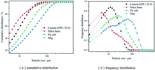
Table 1. The main chemical composition of cement, FA, GGBFS, and SF(%).
The cement is from Shandong Weifang Zhucheng Cement Company (China). The fly ash is Class II from Weifang Power Plant, Shandong Province (China). The ground granulated blast furnace slag is S95 from Henan Province Hengyuan New Material Company (China). The silica fume is from Shandong Zibo Boken Company (China) with a SiO2 content of 85%–95%. The chemical composition of cementitious materials is shown in .
The manufactured sand has a fineness modulus of 2.31 and a maximum size of 3 mm from Qingdao (China). The highly effective water-reducing agent (WRA), a polycarboxylic acid containing 25%·solid content, was used. The product is·manufactured·by Sobute Material Company (China). Additionally, as a thickening agent, hydroxypropyl methylcellulose (HPMC), with a viscosity of 200,000 mPa·s, is sourced from Shanghai Chengi Chemical Company (China).
In the current study, the investigation was conducted based on three mixture designs from previous studies [Citation31], shown in . The substitution rate of cement is zero for the reference group, and the substitution rate of cement was 50% and 40%, respectively, for the other two mixtures. The dosages of the WRA and HPMC were determined based on the printability evaluation, see .
Table 2. Mixture design of 3DCP (kg/m3).
2.2. Experimental procedures
2.2.1. Printability tests
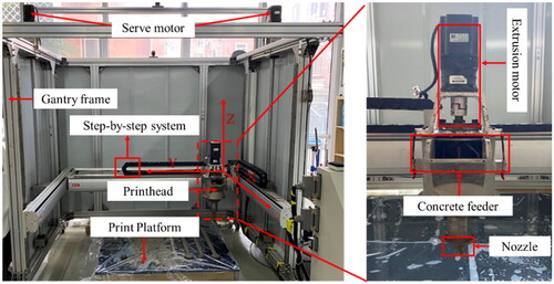
This study adopted a gantry-type 3D printing frame machine featuring a square frame measuring 2 m in width, length, and height, respectively. The printer integrated a commercial software-based external control system, a stepping device, and a print head assembly. Meanwhile, the supplementary components encompassed the overall framework and print platform.
The 3D printing frame machine was operated through the external control system to manage the overall stepping. The servo motors enable precise position control at an accuracy of 0.01 mm, facilitating a single axis stepping speed ranging from 0 to 50 mm/s in three different directions. The printer is shown in . To ensure smooth printing of materials, the extrusion screw speed was fixed at 1 mm/s, while the print nozzle’s travel speed was set to 35 mm/s. Additionally, the print nozzle had a diameter of 20 mm and was positioned 10 mm from the print plane. The printability test was conducted with a print layer thickness of 10 mm, and the print test shape was a bar shape.
Figure 2. Gantry-type 3D Concrete printer.
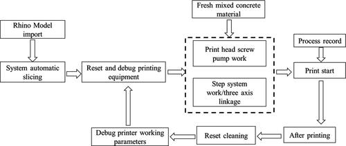
The Gantry 3D printing frame machine software controlled the three-axis linkage printing. The workflow is shown in .
Figure 3. Workflow of 3D concrete printing process.
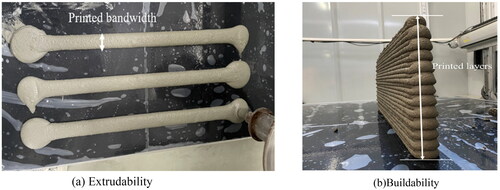
Extrudability was tested by designing three print strips, each with a print length of 300 mm, with the apparent quality of the extruded strips, strip width, and extrusion continuity as the primary evaluation indexes, as shown in . Buildability was evaluated by printing a single multi-layer concrete element with a length of 500 mm, and a layer height of 10 mm, as shown in .
Figure 4. Evaluation of extrudability and buildability.
2.2.2. Mechanical tests
The schematic view of the mechanical tests is shown in . The figure illustrates that elements were initially printed at dimensions of 600 mm × 50 mm × 50 mm, subsequently divided into prismatic specimens (40 mm × 40 mm × 160 mm) and cubic specimens (40 mm × 40 mm × 40 mm). The mold cast samples were prepared with the same dimensions. Mechanical tests comprised 72 prismatic specimens for flexural strength and 108 cubic specimens for compressive strength evaluation (see ). Note that compressive strength was investigated in three different loading directions, while for flexural strength, only the loading direction where the load is perpendicular to the printing direction was considered, as previous studies have demonstrated to be the most vulnerable direction [Citation25]. The specimens were placed in standard curing for 1d, 3d, 7d, and 28d, respectively (curing conditions: temperature: 20 °C ± 2 °C, relative humidity: 95% ± 5%).
Figure 5. 3D Printed specimens for mechanical tests.
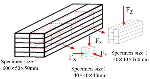
Table 3. The number of mechanical property test specimens.
2.2.3. Water absorption tests
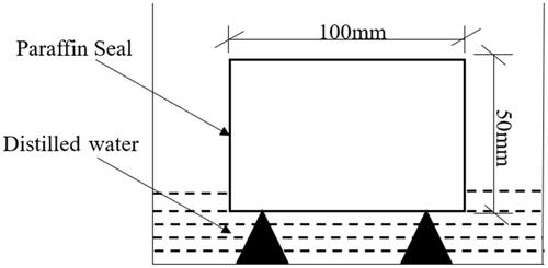
The capillary water absorption test was used to investigate the impermeability of the 3D printed specimens after their hardening. Firstly, after curing for 28 d, one smooth surface of the 3D printed specimen (size of 100 mm × 100mm × 50mm) was selected towards the water. The coating work was completed, and the remaining surfaces (top and lateral surfaces) were sealed with paraffin to ensure one-dimensional water absorption. A triangular block supported the specimens to ensure the water surface was 5 ± 1 mm above the coated surface, as shown in . The specimens were placed in the water for 48 hours. The mass of the specimen was weighed at 0, 1, 2, 4, 8, 12, 24, 36, and 48 h, respectively. The amount of water absorbed by the capillary of the concrete specimen at different times was calculated according to the open square law of time. For each series, the test was repeated three times.
Figure 6. Schematic diagram of capillary water absorption test.
2.2.4. Chloride penetration tests
In addition to the water absorption test, chloride penetration tests were carried out using the samples at the age of 28 d, see . The testing procedure was as follows:
Figure 7. Concrete chloride titration test.
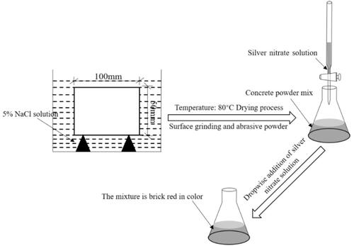
Upon completion of the drying of specimens, the designated molding surface underwent polishing while the remaining surface was coated with paraffin wax. Subsequently, the test pieces were submerged in a 5% sodium chloride solution for 28 d. The test solution was replaced every 14 d to maintain the erosive environment.
The specimens, after soaking, underwent a drying process in an oven lasting 2 d, maintaining a temperature of 80 °C. Subsequently, milling of the specimens occurred along the surface affected by chloride intrusion, with a milling depth of 1 mm per pass. This milling process continued until reaching a total depth of 20 mm inward.
20 ml of sodium chloride standard solution was taken in a triangular flask, and 10 drops of potassium chromate reagent were added. After that, the silver nitrate solution was titrated (0.02 mol/L) until it turned brick red. The volume of silver nitrate consumed was recorded and the chloride ion content was calculated at different depths of the specimen. For each series, the test was repeated three times.
3. Result and discussion
3.1. Printability evaluation
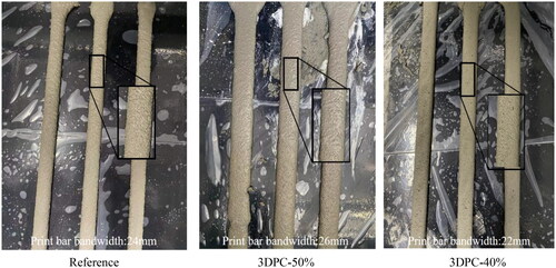
Both the polycarboxylic acid water-reducing agent and the cellulose ether are compounds used to improve the printable performance of the concrete used in the paper. The three mixing ratios of the actual extruded widths of printed strips were 24, 26, and 22 mm. It is clear from that the surface of the extruded strips does not have large pores and apparent defects. The extrusion cross-section at the beginning and end of the printed strip is different, a phenomenon mainly due to the printing process, whose print nozzles cannot control the stopping of the material in time at the beginning and end of the printing process. The printed width deviation compared with the printhead size (20 mm) showed that the 3DPC-50% was the largest, followed by the reference group, and the smallest was the 3DPC-40%. The above results are mainly because FA and GGBFS are added to the 3DPC-50% ratio, and the special structural form of FA can form a “ball bearing effect” to improve the fluidity of the print material further, while SF and GGBFS are added to the 3DPC-40% ratio. The addition of SF can effectively fill the pores of the printing material, thus reducing its fluidity. It can be claimed that the overall extrudability of all the test groups meets the requirements of the printed concrete properties.
Figure 8. Extrudability test under different ratios.
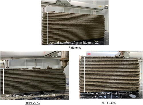
The buildability comparison of different mixtures is shown in . It shows that the extrusion bar at the print nozzle breaks down significantly as the number of layers continues to increase, with the three mixing ratios allowing for 22, 18, and 26 consecutive layers to be printed, respectively. The printing opening time of the printed concrete mixture is less than the time required to extrude the concrete during the printing operation [Citation32], resulting in breakage of the extrusion bars of the extrusion nozzle, which can be adjusted at a later stage by the use of retarders or accelerators, depending on the actual printing composition.
Figure 9. Building test under different ratios.
3.2. Mechanical properties
3.2.1. Compressive strength
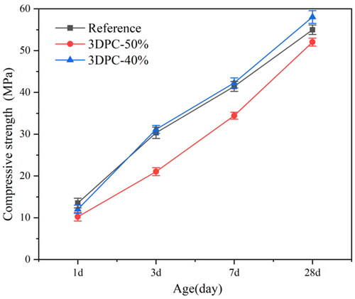
The compressive strengths of mold-cast concrete specimens at 1, 3, 7, and 28 d are shown in . The black, blue, and red color lines represent the reference group, the 3DPC-40% group, and the 3DPC-50% group, respectively. The figure demonstrates a shared upward trajectory in concrete strength across the three groups. The compressive strength of 3DPC-40% nearly aligns with that of the reference group without substitution at different ages. At the same time, a significant early-stage decrease is evident in 3DPC-50%. Specifically, at the age of 3 days, 3DPC-50% exhibits only 30.7% of the compressive strength seen in the reference group, and this diminishes further to just 16.9% after 7 d. This reduction is primarily attributed to the considerable use of fly ash, which adversely impacts early strength. At the age of 28 d, the compressive strength of the mixture 3DPC-50% reaches 52 MPa, while the mixture 3DPC-40% and the reference mixture achieve strengths of 58 MPa and 55 MPa, respectively. It demonstrated that concrete with reduced cement content meets the required compressive strength despite initial setbacks in early strength due to higher fly ash content.
Figure 10. Variation of compressive strength of mold-cast concrete at different ages.
The changes in compressive strength of 3D printed specimens at different ages of 1, 3, 7, and 28 d in different loading directions are shown in . The compressive strengths of the three mixtures increase with age increasing for three loading directions. Meanwhile, the compressive strengths of the 3D printed concrete in X, Y, and Z directions are smaller than those of the mold cast concrete (shown in ). Among them, the compressive strengths in the Z direction (shown in ) is the highest and similar to those molded ones, while the compressive strength in the X, Y direction (shown in ) is relatively low, which is in line with the findings of Ding et al. [Citation33]. The compressive strength decreases in the X loading direction can be due to the weak interlayer bond of 3D printed elements. The higher compressive strengths in the Z loading direction can be due to the better interlayer bond, which results in higher strengths of the concrete in that direction.
Figure 11. Compressive strength of 3D printed specimens at different loading directions.
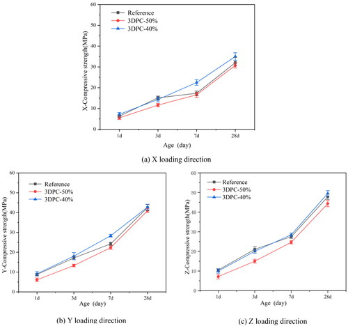
It is clear from that the printing direction significantly affects the mechanical strength of the printed specimens. The 28-day compressive strengths, irrespective of mixes, are 32.1 MPa–49.5 MPa. The 28 d compressive strengths of the X, Y, and Z direction printed specimens in the reference group are 58.4%, 77.5%, and 86.9% of the strengths of the molded concrete specimens in this proportion, respectively. The 28 d compressive strengths of the X, Y, and Z direction printed specimens in the 3DPC-50% group are 59.0%, 78.8%, and 85.2% of those of mold cast specimens in the same proportion, respectively. The 28 d compressive strengths of the X, Y, and Z direction of 3D printed specimens in the 3DPC-40% group are 59.0%, 78.8%, and 85.2% of the values of their mold cast counterparts with the same proportion, respectively. The main reason is that the 3D concrete printing process leads to the different pore distribution of concrete. The 28d compressive strength of 3DPC-40% printed specimens in the Z direction is 3.5% and 11.7% higher than that of the reference group and 3DPC-50% Z-direction printed specimens, respectively, and that of Y direction is 5.2% and 9.3% higher than that of the reference group and 3DPC-50% Y-direction printed specimens, respectively. 5.2% and 9.3%. The 28d compressive strength in the X direction was 9.0% and 14.0% higher than that of the reference group and 3DPC-50% X direction printing strength, respectively. The results show that the reasonable addition of mineral dopants increase the interlayer porosity, resulting in more obvious anisotropy of 3D printed concrete.
3.2.2. Flexural strength
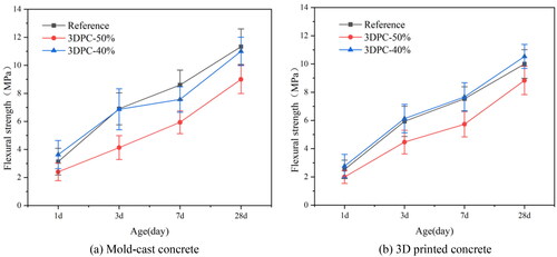
The variation rule of flexural strength of printed concrete under different ratios is shown in . It can be seen from the figure that the flexural strength of the three groups of concrete ratios increases with age, and there is a significant difference between the flexural strength of the molded and printed specimens. At the ages of 1d and 3d, the flexural strength of the molded specimens is 11%–15% higher than that of the printed specimens. Moreover, the difference between the two strengths is decreased at 28d. At 1d, the strength of 3DPC-40% cast-in-place specimens is 3.6 MPa, while the strength of printed concrete was 2.8 MPa. This is mainly due to interlayer pores, which leads to the printed components’ early strength decrease. Luckily, the strength of the printed specimens at 28d is nearly that of the cast-in-place specimen. They are 11.0 and 11.4 MPa, respectively. This indicates that the strength of the printed specimens gradually approaches that of the cast-in-place specimens with the age increasing. This is mainly due to the continuous hydration reaction in the mix, which generates many flocculated structures to fill the printed specimens’ interlayer pores, further enhancing the strength of the printed specimens. Therefore, using industrial solid waste as a substitute for cement can also keep the strength of the printed specimens and meet the requirements under the condition that the cement amount decreases.
Figure 12. Flexural strength of mold cast and 3D printed specimens.
3.3. Impermeability evaluation
3.3.1. Capillary water absorption
The variation of capillary water absorption of the developed mixtures in the current study is shown in . It can be seen from the figure that the water absorption of each group of printed specimens increases with time, and the water absorption speed grows fast in the early stage and slows down in the later stage. This is mainly because large capillary pores are encountered at the initial stage, which increases water absorption. The internal pores become smaller with the hydration developing at the later stage. Thus, the growth rate of water absorption gradually decreases.
Figure 13. Capillary water absorption curve.
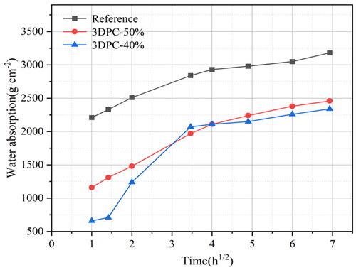
At the age of 1 h, the capillary water absorption of the concrete in the reference group is the highest, which can reach 2210 g/cm2, while the capillary water absorption of the concrete in the 3DPC-50% is lower, with a value of 1160 g/cm2. The capillary water absorption of the concrete in the 3DPC-40% is the lowest, with a value of 660 g/cm2. At 48 h, the water absorption of the pure cement group, 3DPC-50%, and 3DPC-40%, reached 3180 g/cm2, 2460 g/cm2, and 2340 g/cm2, respectively. The test results show that the water absorption of the benchmark group is the largest, while the water absorption of 3DPC-50% and 3DPC-40% are 77.4% and 73.6% of that of the benchmark group, respectively. This is mainly because including fly ash and mineral powder can improve the compactness of the slurry. Although the specific surface area of silica fume is large, it can fill the pores and improve the impermeability of concrete [Citation34,Citation35]. The above pattern indicates that in the 3D printed concrete with the substitution of SCMs, the capillary water absorption can be effectively reduced by incorporating fly ash and mineral powder.
3.3.2. Chloride content
The chloride ion content of concrete with different ratios is shown in , which indicates that the chloride ion content changes gradually to varying depths after being immersed in NaCl solution with a mass fraction of 5%. It can be seen from the figure that the chloride ion content of the benchmark group is always greater than that of 3DPC-50% and 3DPC-40% at all depths. Finally, the chloride ion content tends to stabilize until the depth reaches 18 mm.
Figure 14. Chloride content curves at different depths.
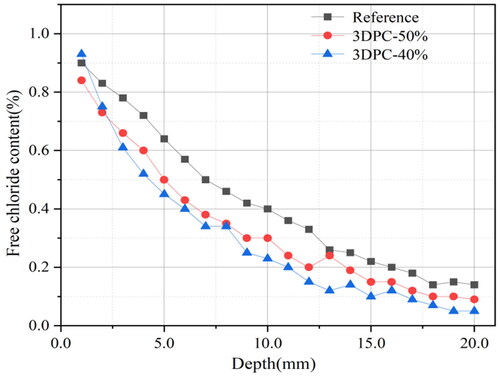
At a depth of 5 mm, the chloride contents of 3DPC-50% and 3DPC-40% are about 78% and 70% of the baseline, while the chloride contents of 3DPC-50% and 3DPC-40% are about 75% and 57.5% of the baseline at a depth of 10 mm. At a depth of 15 mm, the chloride content of 3DPC-50% and 3DPC-40% are about 68% and 45.5% of the baseline, while the chloride content of 3DPC-50% and 3DPC-40% are about 64% and 37.5% of the baseline at a depth of 20 mm. These data indicate that the chloride content of 3DPC-50% and 3DPC-40% is lower than that of the reference group, with the depth increasing. This is mainly due to two reasons. On the one hand, including slag increases the aluminum phase’s content in the cementitious system, which adsorbs some chloride ions. On the other hand, the appropriate amount of fly ash and silica fume can refine the concrete pores and impede the transport of chloride ions, thus improving the resistance to chloride permeability [Citation2,Citation36].
In summary, the permeability law of different concrete ratios is the same, but the durability effect can be reduced by improving the concrete ratios. More detailed permeability tests are needed for large-scale applications in actual projects.
4. Conclusions
The current study aims to reduce the carbon footprint of 3D-printed concrete by substituting partial cement in the mixture. Different supplementary cementitious materials were adopted, including fly ash, ground granulated blast furnace slag, and silica fume. The mechanical properties and permeability evaluation of 3D printed concrete with a low cement content was carried out. Based on the experimental results and discussion, the following conclusions can be drawn:
Reducing the cement content in 3D printable concrete mixtures decreases early strength, while the 28-day strength remains relatively unaffected. In specific loading directions, a 40% cement substitution can even result in a slightly higher 28-day strength than the reference group.
The use of supplementary cementitious materials in 3D printable concrete improves the anisotropic behavior, with the highest strength observed in the direction parallel to the load. This anisotropy is due to increased interlayer porosity partially from the mineral dopants.
The addition of supplementary cementitious materials significantly reduces capillary water absorption and chloride ion penetration depth in concrete, compared to the reference mixture, thereby enhancing the material’s durability and resistance to environmental degradation.
Disclosure statement
No potential conflict of interest was reported by the author(s).
Additional information
Funding
References
- Lu B, Weng Y, Li M, et al. A systematical review of 3D printable cementitious materials. Constr Build Mater. 2019;207:477–490. doi: 10.1016/j.conbuildmat.2019.02.144.
- Ma G, Li Z, Wang L, et al. Micro-cable reinforced geopolymer composite for extrusion-based 3D printing. Mater Lett. 2019;235:144–147. doi: 10.1016/j.matlet.2018.09.159.
- Kedir F, Hall DM. Resource efficiency in industrialized housing construction–a systematic review of current performance and future opportunities. J Cleaner Prod. 2021;286:125443. doi: 10.1016/j.jclepro.2020.125443.
- Hossain MA, Zhumabekova A, Paul SC, et al. A review of 3D printing in construction and its impact on the labor market. Sustainability. 2020;12(20):8492. doi: 10.3390/su12208492.
- Li VC, Bos FP, Yu K, et al. On the emergence of 3D printable engineered, strain hardening cementitious composites (ECC/SHCC). Cem Concr Res. 2020;132:106038. doi: 10.1016/j.cemconres.2020.106038.
- Panda B, Tay YWD, Paul SC, et al. Current challenges and future potential of 3D concrete printing: aktuelle herausforderungen und zukunftspotenziale des 3D‐druckens bei beton. Materialwissenschaft Werkst. 2018;49(5):666–673. doi: 10.1002/mawe.201700279.
- Paul SC, Van Rooyen AS, van Zijl GP, et al. Properties of cement-based composites using nanoparticles: a comprehensive review. Constr Build Mater. 2018;189:1019–1034. doi: 10.1016/j.conbuildmat.2018.09.062.
- Paul SC, Tay YWD, Panda B, et al. Fresh and hardened properties of 3D printable cementitious materials for building and construction. Arch Civ Mech Eng. 2018;18(1):311–319. doi: 10.1016/j.acme.2017.02.008.
- Mohan MK, Rahul A, Van Tittelboom K, et al. Rheological and pumping behaviour of 3D printable cementitious materials with varying aggregate content. Cem Concr Res. 2021;139:106258. doi: 10.1016/j.cemconres.2020.106258.
- Tinoco MP, de Mendonça ÉM, Fernandez LIC, et al. Life cycle assessment (LCA) and environmental sustainability of cementitious materials for 3D concrete printing: a systematic literature review. J Build Eng. 2022;52:104456. doi: 10.1016/j.jobe.2022.104456.
- Hambach M, Rutzen M, Volkmer D. Properties of 3D-printed fiber-reinforced Portland cement paste. In: Sanjayan JG, Nazari A, Nematollahi B, editors. 3D concrete printing technology. Amsterdam: Elsevier; 2019. p. 73–113.
- Pasupathy K, Ramakrishnan S, Sanjayan J. 3D concrete printing of eco-friendly geopolymer containing brick waste. Cem Concr Compos. 2023;138:104943. doi: 10.1016/j.cemconcomp.2023.104943.
- Menna C, Mata-Falcón J, Bos FP, et al. Opportunities and challenges for structural engineering of digitally fabricated concrete. Cem Concr Res. 2020;133:106079. doi: 10.1016/j.cemconres.2020.106079.
- Souza MT, Ferreira IM, de Moraes EG, et al. 3D printed concrete for large-scale buildings: an overview of rheology, printing parameters, chemical admixtures, reinforcements, and economic and environmental prospects. J Build Eng. 2020;32:101833. doi: 10.1016/j.jobe.2020.101833.
- Han Y, Yang Z, Ding T, et al. Environmental and economic assessment on 3D printed buildings with recycled concrete. J Cleaner Prod. 2021;278:123884. doi: 10.1016/j.jclepro.2020.123884.
- Mechtcherine V, Nerella VN, Will F, et al. Large-scale digital concrete construction–CONPrint3D concept for on-site, monolithic 3D-printing. Autom Constr. 2019;107:102933. doi: 10.1016/j.autcon.2019.102933.
- Panda B, Tan MJ. Rheological behavior of high volume fly ash mixtures containing micro silica for digital construction application. Mater Lett. 2019;237:348–351. doi: 10.1016/j.matlet.2018.11.131.
- Liu Z, Li M, Weng Y, et al. Mixture design approach to optimize the rheological properties of the material used in 3D cementitious material printing. Constr Build Mater. 2019;198:245–255. doi: 10.1016/j.conbuildmat.2018.11.252.
- Liu X, Li Q, Wang L, et al. Systematic approach for printability evaluation and mechanical property optimization of spray-based 3D printed mortar. Cem Concr Compos. 2022;133:104688. doi: 10.1016/j.cemconcomp.2022.104688.
- Arunothayan AR, Nematollahi B, Ranade R, et al. Digital fabrication of eco-friendly ultra-high performance fiber-reinforced concrete. Cem Concr Compos. 2022;125:104281. doi: 10.1016/j.cemconcomp.2021.104281.
- Chaves Figueiredo S, Romero Rodríguez C, Y. Ahmed Z, et al. Mechanical behavior of printed strain hardening cementitious composites. Materials. 2020;13(10):2253. doi: 10.3390/ma13102253.
- Pham L, Tran P, Sanjayan J. Steel fibres reinforced 3D printed concrete: influence of fibre sizes on mechanical performance. Constr Build Mater. 2020;250:118785. doi: 10.1016/j.conbuildmat.2020.118785.
- Moelich GM, Kruger J, Combrinck R. Plastic shrinkage cracking in 3D printed concrete. Comp B Eng. 2020;200:108313. doi: 10.1016/j.compositesb.2020.108313.
- Kazemian A, Yuan X, Cochran E, et al. Cementitious materials for construction-scale 3D printing: laboratory testing of fresh printing mixture. Constr Build Mater. 2017;145:639–647. doi: 10.1016/j.conbuildmat.2017.04.015.
- Le TT, Austin SA, Lim S, et al. Hardened properties of high-performance printing concrete. Cem. Concr. Res. 2012;42(3):558–566. doi: 10.1016/j.cemconres.2011.12.003.
- Rahul A, Santhanam M, Meena H, et al. Mechanical characterization of 3D printable concrete. Constr Build Mater. 2019;227:116710. doi: 10.1016/j.conbuildmat.2019.116710.
- Lee H, Kim J-HJ, Moon J-H, et al. Evaluation of the mechanical properties of a 3D-printed mortar. Materials. 2019;12(24):4104. doi: 10.3390/ma12244104.
- Ma G, Li Z, Wang L. Printable properties of cementitious material containing copper tailings for extrusion based 3D printing. Constr Build Mater. 2018;162:613–627. doi: 10.1016/j.conbuildmat.2017.12.051.
- Panda B, Paul SC, Tan MJ. Anisotropic mechanical performance of 3D printed fiber reinforced sustainable construction material. Mater Lett. 2017;209:146–149. doi: 10.1016/j.matlet.2017.07.123.
- Bran Anleu PC. Quantitative micro XRF mapping of chlorides: possibilities, limitations, and applications, from cement to digital concrete [Ph.D. thesis]. ETH Zurich; 2018. https://doi.org/10.3929/ethz-b-000328911.
- Cui W, Wang T, Chen X, et al. Study of 3D printed concrete with low-carbon cementitious materials based on its rheological properties and mechanical performances. J Sustain Cem Based Mater. 2023;12(7):832–841. doi: 10.1080/21650373.2023.2189172.
- Le TT, Austin SA, Lim S, et al. Mix design and fresh properties for high-performance printing concrete. Mater Struct. 2012;45(8):1221–1232. doi: 10.1617/s11527-012-9828-z.
- Ding T, Xiao J, Zou S, et al. Hardened properties of layered 3D printed concrete with recycled sand. Cem Concr Compos. 2020;113:103724. doi: 10.1016/j.cemconcomp.2020.103724.
- Nodehi M, Aguayo F, Nodehi SE, et al. Durability properties of 3D printed concrete (3DPC). Autom Constr. 2022;142:104479. doi: 10.1016/j.autcon.2022.104479.
- Zhang Y, Zhang Y, Yang L, et al. Hardened properties and durability of large-scale 3D printed cement-based materials. Mater Struct. 2021;54(1):1–14. doi: 10.1617/s11527-021-01632-x.
- Marchon D, Kawashima S, Bessaies-Bey H, et al. Hydration and rheology control of concrete for digital fabrication: potential admixtures and cement chemistry. Cem Concr Res. 2018;112:96–110. doi: 10.1016/j.cemconres.2018.05.014.
Appendix A
Table A1. Main performance test results of cement.
Table A2. Main performance test results of FA.
Table A3. Main performance test results of GGBFS.
Table A4. Main performance test results of SF.