
Abstract
Shear localization is an important failure mechanism in crystalline solid materials. However, while nanograins (NGs) are universally observed in shear bands, their connection with the formation of the bands is not clear yet. Based on molecular dynamics (MD) simulations, we propose that the shear localization evolves as a percolative process of deformation zones between NGs. The presence of NGs is a necessary condition to relieve some of the elastic energy by dislocation emission and absorption. Moreover, the density and spatial arrangement of those grains are of prime importance to accelerate or delay the formation of a strong localization path.
Dynamic shear localization is a failure mechanism that is a characteristic of high-rate deformation. Narrow strain localization bands, also called adiabatic shear bands (ASBs), tend to develop abruptly, leading to local material softening and catastrophic failure.[Citation1] It has long been argued that the thermo-mechanical coupling effect is responsible for ASB formation in crystalline solids.[Citation2] However, the recent observations of dynamically recrystallized nanograins (NGs) in hexagonal closed packed (HCP) metals,[Citation3,Citation4] which appear locally long before the ASB has formed, have led to a new paradigm, namely that dynamic shear localization is driven by microstructural evolutions, rather than by thermal softening. This claim has been supported by recent numerical simulations, which clarified the respective role of microstructural and thermal softening factors.[Citation5] However, the numerical simulations that were aimed at replicating the experimental results did not look into detail at the actual microstructural deformation mechanisms, since a coarse-grained approach was adopted. Moreover, the local matrix softening related to NG formation was surmised based mainly on their low density of dislocations. Therefore, the open issue is whether NGs, which are formed in a crystalline matrix, can actually soften the latter to an extent that strain localization develops abruptly, and if this is the case, how does that happen with respect to the density and spatial layout of those NGs. In other words, does the presence of NGs precipitate dynamic shear localization?
To address this general problem of the heterogeneity of the plastic deformation at its very basic scale, continuum-based simulations are either cumbersome or inadequate. Thus, this study relies on molecular dynamics (MD) simulations, which on the one hand are inherently limited in size, but on the other hand have the great advantage that the dislocation mechanisms manifest themselves naturally; thus, providing a physical picture of the phenomenon at hand. We construct here a model system to show that the presence of NGs by itself does indeed promote a localized deformation mode, while identifying the spatial distribution requirements that accelerate or slow down the process. In the spirit of previous suggestions that shear band formation is a percolative process in amorphous materials,[Citation6,Citation7] we show in this letter that shear band formation can similarly be rationalized as a percolation process [Citation8] leading to deformation zones between NGs in crystalline structures.
The MD simulation code LAMMPS [Citation9] is employed to study the deformation of a HCP lattice with an internal microstructure of NGs. We choose Mg as a representative material using an interatomic interaction described by the embedded atom potential (EAM).[Citation10] This crystallographic structure allows for dislocations on several slip systems to be nucleated when considering a fully periodic slab with a shorter dimension along the direction. NGs are inserted into the lattice by rotating hexagonal domains of atoms around the
axis by 15° or 37° with respect to the matrix. As we shall further emphasize, the grain boundary formed in these angles gives rise to symmetric dislocation nucleation under tensile stress. The computational cell is first relaxed with the conjugate gradient technique, followed by a relaxation of the stresses via MD time steps, employing the Parrinello–Rahman barostat at T=10°K. Then, the slab is strained along the
direction at a constant strain rate of 109 s−1. This direction is chosen in order to activate pairs of slip systems (e.g. on
and
planes), so that there will be no preferential slip direction which arises solely from the crystal structure. During the deformation, the resulting stress along the tensile direction is calculated. The lattice's microstructure is identified according to the bond order parameter q6 [Citation11] and visualized using OVITO (for details, see [Citation12]). More information on the simulation setup is given in Section A in the Supplementary Information.
We first consider homogeneously distributed NGs on a cubical subset of lattice points ((a)). The simulations are repeated with different sizes of NGs, while the distance between the center of the grains is kept constant. Characteristic stress–strain curves are shown in (b) for a few grain sizes, accompanied by the corresponding atomic configurations during the deformation. Since all the grains are self-similar, their size is characterized by a single parameter, α, which is the largest distance between atoms on the grain boundary of the NG (see the inset in (b)). Four distinct stages during the deformation can be identified in the stress–strain curves: the first corresponds to an elastic regime (marked as (I) in (b)), which deviates from linearity as the tensile strain increases. In all the simulations, the tensile stress saturates at a value of about 1.9 GPa and remains almost constant during the deformation (second stage marked as (II) in (b)). In matrices with the smaller grains (8 nm and below), this stage ends at a tensile strain of about 7%, followed by a third stage during which the material hardens (marked as (III) in (b)). Finally, as the strain further increases, noticeable softening occurs (fourth stage, marked as (IV) in (b)). The extent of the hardening stage decreases as the grains are made bigger, to an extent that beyond a size of 8 nm, the hardening stage completely disappears and the fourth stage follows directly the second stage. Let us denote here the strain at which softening commences as the failure strain.
Figure 1. Deformation of lattices with a homogeneous distribution of grains. (a) A representative case of the microstructure after the relaxation (before applying a tensile stress). Grain boundaries, dislocations and stacking faults are shaded in light gray. (b) Stress–strain curves for different grain sizes. (c) The atomic configuration at the onset of the softening stage. A few dislocations that are emitted into the matrix can be observed.
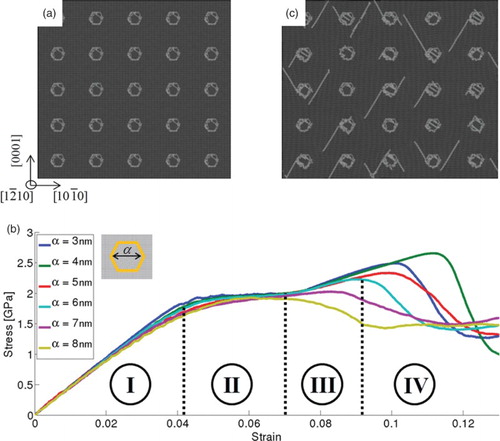
Microstructural evolutions along the deformation are considered next. During the first stage, no prominent dislocation activity is observed. During the second stage, the main dislocation activity is confined inside the grains and their boundaries. This activity translates into a slight rotation of the grains (through reconstruction of the grain boundaries) but mainly to nucleation of internal dislocations, thereby relieving the internal stresses without plastic deformation in the matrix (outside the NGs). In other words, dislocations’ nucleation into the matrix is not observed. Once it becomes harder to deform the material via grain rotation or shearing mechanisms, hardening commences (third stage). As the strain increases, the stresses are relieved by nucleation and emission of partial dislocations on the grain boundaries, which glide into the matrix on two pyramidal planes and
((c)). It is important to mention that the nucleated dislocations are distributed evenly between the two planes and that the rotation angle of the NGs did not impose any directionality due to preferential nucleation into one of these slip planes. The partial dislocations glide away from the grains, and at the onset of the fourth stage, they annihilate on a grain boundary of a different NG, which in some cases results in a persistent faulted plane between two different grain boundaries. This observation is cardinal, in the sense that the failure strain is apparently related to the absorption of dislocations on grain boundaries, which results in a localized deformation around the stacking fault. In addition, when a dislocation is nucleated into the matrix and terminates on another grain, it releases in some cases the elastic energy stored within the grain boundary by triggering emission of new dislocation from the grain boundary, which eventually promotes to softening. We refer the reader to Section B in the Supplementary Information for more details on the dislocation mechanisms. This observation rationalizes the decrease in the failure strain as the grain size is increased, i.e. the dislocations’ mean-free path in the matrix decreases as the size increases. Thus, it is suggested that the important parameter that controls the failure strain is the distance between grains.
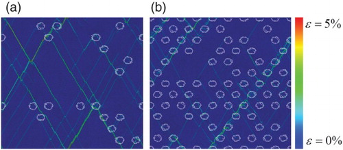
In that spirit, for a given grain size, one can expect the failure strain to decrease as the density of NGs along the slip directions increases. To further examine this point, computational cells with grains aligned along specific directions were constructed and strained as before. The dimensions of the computational cell in each case are determined so that the alignment of the grains will be compatible with the periodic boundary conditions, so that the NGs’ area is actually aligned on an infinitely straight line. The characteristics of the mechanical response are similar to the case of a homogeneous distribution of grains, as shown in (a). Moreover, the stress–strain curves are indifferent to the grains’ distribution up to a tensile strain of 7%, i.e. dislocation activity occurs locally within the grain and on its boundary, independent of the neighboring grains. However, the hardening and softening stages depend on the arrangement of the grains. For instance, the softening stage is postponed when the grains are aligned along the direction, whereas different arrangements may decrease the failure strain. In particular, the material undergoes relatively low hardening when the center of the NGs is aligned along
and
directions (pyramidal planes), which are the preferable directions for dislocation nucleation and glide, found previously with the homogeneous distribution of grains. Examination of the microstructure at failure in each case shows a distinct difference between the case where the grains are aligned along the
and
directions. Here, the major difference is the distance between grains along the activated slip directions. This distance (through the periodic boundary conditions) is large and equal for both activated slip directions in the former case (grain aligned along the
direction). As a result, there is no preferable path for the deformation and the strain is not localized ((b)). This contrasts with the case of grains aligned along the
direction, for which this distance becomes the shortest. Thus, dislocations nucleated outside the grain are absorbed in the adjacent grain boundary more rapidly, with only minor interaction within the matrix, leaving a persistent fault between the grains. As the deformation proceeds, more dislocations follow these shorter paths between grains, leading to a localization of the deformation along these paths, as can be seen from (c).
Figure 2. Deformation of lattices with a directional arrangement of grains. (a) Stress–strain curves for different directions. The angle of the grain alignment is measured from the horizontal axis ([10¯ 10] direction). Von-Mises local shear strain maps at total tensile external strain of 10% for grains aligned along angles of (b) 0° ([10¯ 10] direction) and (c) 60° (near [10¯ 12] direction) are shown. A clear strain localization is identified in the latter case.
![Figure 2. Deformation of lattices with a directional arrangement of grains. (a) Stress–strain curves for different directions. The angle of the grain alignment is measured from the horizontal axis ([10¯ 10] direction). Von-Mises local shear strain maps at total tensile external strain of 10% for grains aligned along angles of (b) 0° ([10¯ 10] direction) and (c) 60° (near [10¯ 12] direction) are shown. A clear strain localization is identified in the latter case.](/cms/asset/2c01a6de-edeb-4ac7-895c-ed7bfbe507db/tmrl_a_957791_f0002_c.jpg)
These simulations suggest that dislocations are responsible for a two competitive process: hardening due to the interaction between dislocation in the bulk and softening when they terminate on the grain boundaries of NGs. For instance, in the case where the grains are aligned along the direction, dislocations interact within the bulk before reaching NGs. When grains are aligned along the
direction, dislocations find soft paths between NGs, rather than interacting within the bulk and softening prevails. Interestingly, when the grains are constructed on the second active slip plane, the direction of the soft path follows the grains (see Section C in the Supplementary Information). This emphasizes the importance of the arrangement of the NGs on the directionality of the deformation.
It is worth mentioning that this behavior is different from that in nano-polycrystalline materials. While in the latter, any morphological change of the NGs involves a coherent deformation of the surrounding NGs,[Citation13] here the NGs are not bounded by other NGs. As a result, upon interaction with dislocations, softening may prevail, while in nano-polycrystalline materials the limitation on grain motion may give rise to hardening.
Based upon these observations, we suggest that recrystallized NGs play a double role in promoting shear localization. Firstly, they release some of the elastic energy stored in the lattice during deformation by nucleating dislocations into the matrix. In addition, dislocations are absorbed on grain boundaries and release some of the elastic energy stored within its grain boundary. In that sense, if dislocations find a short path between the NGs, the deformation will be localized around this path, leading to failure via shear banding. If this path, which we denote as a soft path, is not short enough, localization of the deformation may be suppressed. Naturally, quantifying the critical soft path length for shear band formation is beyond the reach of atomistic simulations, and larger simulations that consider also the dislocations’ microstructure should be employed (like discrete dislocation dynamics simulations). However, we believe that the typical length of a soft path should correspond to the mean-free path of dislocations in the matrix. If the distance between NGs along the soft path is larger than that, the dislocations will be stored in the matrix and not at the grain boundaries of the NGs. Devincre et al. [Citation14] reported that the mean-free path of dislocations in Cu is of the order of a few micrometers. Adopting this value for other materials, we propose that this order of magnitude is also the minimal distance between recrystallized NGs along the soft path in order to initiate a shear band.
However, the probability of having all NGs aligned along one slip plane is highly unlikely in a real scenario. Can the material find soft paths when NGs are not aligned on a single slip plane? It can be surmised that the material is weaker as the grains are denser, based on the premise of an increased probability for the dislocations to find a soft path between the grains. To demonstrate that, we next apply a tensile strain on a system with a distribution of NGs embedded onto subset of points on a hexagonal sub-grid. The grains’ size corresponds to α=5 nm. We emphasize that this subset of points is chosen randomly in each simulation. This construction generates different configurations with NGs aligned along different slip planes. Three hundred and twenty configurations were generated in total (two of them are presented in ).
Figure 3. Two representative cases of an inhomogeneous distribution of the NGs with (a) a diffuse and (b) a strong localization. The colors correspond to the Von-Mises local shear strain, at an external tensile strain slightly above the failure strain. For convenience, the atoms within grain boundaries are shaded in light blue on the shear strain maps.
The average failure strain is calculated from 20 simulations with different arrangements for a given number of grains, and in we plot the averaged values for failure strain as a function of the density of NGs. The error bars indicate the variance of the results around the average value. The failure strain decreases as the density of NGs increases, whereas it is not strongly sensitive to the distribution of NGs for a given density, despite the stochastic nature of this process.
Figure 4. The failure strain and a dimensionless normalized value as a function of the density of NGs. The plot, which summarizes all 320 simulations, shows that failure strain is decreasing with an increase in the density of grains, and above a certain threshold the failure strains become microstructure- independent. This threshold can be viewed as a percolation threshold.
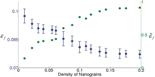
A closer look of the microstructure at the failure strain in each MD simulation rationalizes the failure strain dependency of the NGs density. At the lower density of NGs, the deformation is indeed localized between the grains but there is no clear soft path through the computational cell. For instance, in (a) some localized ribbons with high shear strains are observed between NGs. However, the low density of NGs within the matrix allows for dislocation interactions within the bulk, which promotes hardening and postponed the failure strain. In this case, the localization can be qualified of diffuse. For the higher density, the deformation finds a soft path between NGs through the whole computational cell. This is demonstrated in (b), where the system finds a soft path along a plane with a high NGs density, which strongly localizes the deformation in a specific direction. In other words, when the arial density of NGs exceeds a certain value, here 14%, a soft path prevails, which leads to a strong shear localization. Once a soft path is found, any additional increase in the density of NGs will only add more possible paths and will no longer affect the failure strain, as can be seen from .
This behavior is definitely reminiscent of a percolative process, which would adequately describe the catastrophic character of adiabatic shear failure through the attainment of a threshold. Based upon these simulations, we propose the following mechanism. At low densities of NGs, some localized deformation between grains may take place, but its contribution to the total deformation is minor, whereas dislocation interactions within the matrix prevail. For high density of NGs, deformation paths between NG become dominant and shear bands are formed.
We note here that the percolative process proposed here is different from the classical mathematical percolation theories in several aspects, and we name here only a few. While we choose a sub-grid, on which the NGs are formed, not all grid points are occupied; dislocations between NGs intersect also within the bulk and contribute to hardening and not only connecting NGs, the probability to nucleate dislocations changes during the process since the grain boundaries of NGs undergo topological changes after absorbing dislocations. Moreover, in practice, the material is recrystallized dynamically to form the NGs, so that the number of occupied sites is a dynamic process, which is definitely not captured by our MD simulations.
Thus, we do not provide here a quantitative description of the process, rather than identifying that such a process takes place in crystalline materials. Percolation of strain localization zones, as the process toward shear bands formation, was already suggested in other type of structures, e.g. amorphous materials.[Citation6,Citation7] However, the dislocation mechanism reported here has not been previously identified as being responsible for the formation of shear bands in crystalline materials. One should recall the results of Osovski and Rittel,[Citation8] who used the Shannon's entropy of the deformed system to identify a similar kind of percolation threshold, albeit based on continuum calculations.
We conclude from the simulations that there is an aerial (volumetric) density threshold of NGs (recrystallized region) above which a soft path will be found. We denote this threshold as the shear band threshold. For instance, if we define a parameter , which is equal to 0 and 1 when the failure strain corresponds to the maximum and minimum values found in our simulations, respectively (see ), the shear band threshold is the value above which
. In our simulations, this threshold corresponds to a density of 14%.
The picture, as being revealed by our MD simulations, clarifies the process of shear bands formation in crystalline materials. During high-strain rate deformation, small recrystallized NGs are formed dynamically within the material, as was previously observed experimentally.[Citation3,Citation4] This microstructural heterogeneity gives rise to the localized deformation between NGs by emitting and absorbing dislocations from and into their grain boundaries. However, this process competes with other dislocation mechanisms in the bulk, like hardening and recovery, and below a certain volumetric density of NGs, dislocation interactions within the bulk dominate, i.e. non-localized deformation prevails. As the deformation proceeds, more NGs are formed dynamically and the relative contribution of localized deformation zones between NGs to the overall deformation increases. If the density of NGs overcomes dynamically the shear band threshold, these localized zones percolate, and form a soft path on which the deformation is strongly localized, leading to the formation of a shear band. In order to meet this condition, the rate at which the NG's recrystallize dynamically, with respect to the hardening and recovery dislocation mechanisms within the bulk, should be high enough. In that sense, dislocation recovery properties, such as cross-slip, which was shown to be a crucial parameter in controlling dislocation cell structures,[Citation15] may be a key mechanism in determining the failure mode. However, once the NGs are formed dynamically, temperature will not have a crucial effect on the dislocation mechanisms reported here. MD simulations at higher temperatures reveal a similar percolative process to the one reported here. In addition, the process reported here is not necessarily particular to an HCP lattice structure and its extension to other structures is planned in the future. Understanding how to control the failure mode in crystalline material can guide us toward designing new materials and tailoring nanoscale structures with enhanced mechanical properties.[Citation16]
As a final remark, one should note that in this work, the NGs are pre-existing in the matrix, so that the failure strain corresponds to the peak stress situation. By contrast, the previous work of Rittel et al. [Citation3] showed that the NGs can form long before the peak stress is reached and those authors identified the onset of localization with this stage. Since the NG formation process is not addressed in this work, the failure strain is the strain corresponding to the peak stress.
Supplementary Online Material
A more detailed information on the simulations is available at http://dx.doi.org/10.1080/21663831.2014.957791
Supplementary material
Download MS Word (3.2 MB)Acknowledgements
We thank Dr. S. Osovski for fruitful discussions. This research is partially supported by the Israel Science Foundation (Grant No. 1656/12).
References
- Bai Y, Dodd B. Adiabatic shear localization: occurrence, theories, and applications. Oxford: Pergamon Press; 1992.
- Zener C, Hollomon JH. Effect of strain rate upon plastic flow of steel. J Appl Phys. 1944;15(1):22–32. doi: 10.1063/1.1707363
- Rittel D, Landau P, Venkert A. Dynamic recrystallization as a potential cause for adiabatic shear failure. Phys Rev Lett. 2008;101(16):165501. doi: 10.1103/PhysRevLett.101.165501
- Rittel D, Wang ZG, Merzer M. Adiabatic shear failure and dynamic stored energy of cold work. Phys Rev Lett. 2006;96(7):075502. doi: 10.1103/PhysRevLett.96.075502
- Osovski S, Rittel S, Venkert A. The respective influence of microstructural and thermal softening on adiabatic shear localization. Mech Mater. 2013;56:11–22. doi: 10.1016/j.mechmat.2012.09.008
- Shi Y, Falk ML. Strain localization and percolation of stable structure in amorphous solids. Phys Rev Lett. 2005;95(9):095502. doi: 10.1103/PhysRevLett.95.095502
- Liu Y, Liu C, Wang W, Inoue A, Sakurai T, Chen M. Thermodynamic origins of shear band formation and the universal scaling law of metallic glass strength. Phys Rev Lett. 2009;103(6):065504. doi: 10.1103/PhysRevLett.103.065504
- Osovski S, Rittel D. Microstructural heterogeneity and dynamic shear localization. Appl Phys Lett. 2012;101(21):211901. doi: 10.1063/1.4767654
- Plimpton S. Fast parallel algorithms for short-range molecular dynamics. J Comp Phys. 1995;117(1): 1–19. doi: 10.1006/jcph.1995.1039
- Liu X-Y, Adams JB. Grain-boundary segregation in Al–10%Mg alloys at hot working temperatures. Acta Mat. 1998;46(10):3467–3476. doi: 10.1016/S1359-6454(98)00038-X
- Steinhardt PJ, Nelson DR, Ronchetti M. Bond-orientational order in liquids and glasses. Phys Rev B. 1983;28(2):784–805. doi: 10.1103/PhysRevB.28.784
- Stukowski A. Structure identification methods for atomistic simulations of crystalline materials. Model Simul Mater Sci Eng. 2012;20(4):045021. doi: 10.1088/0965-0393/20/4/045021
- Wendy XG, Loynachan CN, Wu Z, Zhang Y-W, Srolovitz DJ, Greer JR. Size-dependent deformation of nanocrystalline Pt nanopillars. Nano Lett. 2012;12(12):6385–6392. doi: 10.1021/nl3036993
- Devincre B, Hoc T, Kubin L. Dislocation mean free paths and strain hardening of crystals. Science. 2008;320(5884):1745–1748. doi: 10.1126/science.1156101
- Landau P, Mordehai D, Venkert A, Makov G. Universal strain–temperature dependence of dislocation structures at the nanoscale. Scripta Mater. 2012;66(3–4):135–138. doi: 10.1016/j.scriptamat.2011.10.012
- He G, Eckert J, Loeser W, Schultz L. Novel Ti-base nanostructure–dendrite composite with enhanced plasticity. Nature Mater. 2003;2:33–37. doi: 10.1038/nmat792