
Abstract
A strain-induced reverse phase transformation from a hexagonal close-packed phase to a face-centered cubic phase was observed under tension at room temperature in electrodeposited nanocrystalline Co-Ni alloys with an average grain size of 15 nm. Such reverse phase transformation was previously observed only on heating. Investigation by transmission electron microscopy suggests a close relationship between the reverse phase transformation and grain growth during the tensile deformation.
1. Introduction
It is generally acknowledged that martensitic transformations can be triggered above the martensite start temperature (Ms) by plastic deformation.[Citation1] The strain-induced martensitic transformation is one of the most important characteristics of shape memory alloys (SMAs), which has been widely investigated in Ni-Ti-based, Fe-based and other typical SMAs.[Citation2] However, there are not many reports about strain-induced reverse transformation, which is an interesting topic.
Meanwhile, when the grain size is reduced to nano scale, nanocrystalline metals and alloys exhibit much different behaviors in comparison to their coarse-grained counterparts.[Citation3–5] Phase transformations have been widely investigated in nanocrystalline Co processed by ball milling,[Citation6,Citation7] surface mechanical attrition treatment [Citation8,Citation9] and high-pressure torsion.[Citation10,Citation11]
Size dependence of the reverse transformation from hcp to fcc phase is still less understood. Binary Co-Ni alloys are selected as the experimental model material in this work for the reason that they exhibit a reversible fcc to hcp phase transformation when Ni content is less than 35at% Ni, as shown in the phase diagram ().[Citation12–15] The phase transformation temperature decreases with increasing Ni content.
Figure 1. Phase diagram of Co-Ni.[Citation12]
![Figure 1. Phase diagram of Co-Ni.[Citation12]](/cms/asset/7386b375-f761-4cbe-b52e-67b953e8f440/tmrl_a_989460_f0001_c.jpg)
Interaction between the reverse transformation and grain growth upon heating in nanocrystalline Co-Ni alloys was taken into consideration.[Citation16,Citation17] Since strain-induced grain growth has been extensively reported in nanocrystalline materials under indentation,[Citation18,Citation19] high-pressure torsion,[Citation20,Citation21] compression [Citation22] and tensile test,[Citation23,Citation24] it is interesting to study the microstructure evolution accompanying a plastic deformation process.
In the present study, an interesting phenomenon of strain-induced phase transformation from hcp to fcc in nanocrystalline Co-31.0at%Ni alloy was observed. Pulse electrodeposition was employed to prepare nanocrystalline Co-Ni alloys with fewer defects and impurities. Phase change and grain growth were studied on Co-(20.6 ± 0.1at%)Ni, Co-(31.0 ± 0.1at%)Ni and Co-(48.0 ± 0.5at%)Ni under tension at room temperature. The close relationship between reverse transformation from hcp to fcc and grain growth during tensile tests was discussed and it suggested a possible mechanism for the strain-induced reverse transformation.
2. Experimental
Nanocrystalline Co-Ni alloys were prepared by pulse electrodeposition. A saccharin-containing electrolyte with contents listed in was used to produce electrodeposits of 20 µm thickness. Analytical grade chemicals and deionized water were used to prepare the solutions. The solution temperature was maintained at 40 ± 1°C by immersing the plating cell in a large volume thermostatted water bath. The cathode substrate was made of 304 stainless steel sheet with a size of 30 mm × 40 mm × 0.5 mm after a passivation treatment by immersion in nitric acid. A graphite sheet with surface area much larger than that of the cathode was used as the anode. Pulsed electrodeposition was carried out galvanostatically using cathodic square wave pulses with complete current cut-off during the interval between the pulses. The pulse plating parameters are given in .
Table 1. Composition of electroplating baths used in the present study.
Table 2. Pulse plating conditions leading to acceptable nanocrystalline Co-Ni deposits from saccharin-containing electrolyte.
Nickel contents in the Co-Ni samples were detected by energy dispersive X-ray analysis (EDX) on a scanning electron microscopy (SEM, FEI Sirion 2000 field emission microscope) and by using inductively coupled plasma optical emission spectrometer (ICP, Thermo iCAP6300). The structure of samples was determined by using X-ray diffraction (XRD, Rigaku D/max-2550/PC, Cu Kα) and the microstructures were investigated by transmission electron microscopy (TEM, JEOL-2100F). Tensile tests were performed using universal material experiment machine (Zwick/Roell Z020), where the strain was measured by using a knife-edge extensometer (makroXtens). Heat evolution was measured by differential scanning calorimetry (DSC, Perkin Elmer Diamond).
3. Results
3.1. Phases and Microstructure of as-deposited Co-Ni Alloys
shows the TEM images and XRD patterns of as-deposited samples with three typical compositions of Co-20.6at%Ni, Co-31.0at%Ni and Co-48.0at%Ni, respectively. It is clear from the bright-field and dark-field micrographs that these electrodeposits have a nanocrystalline structure with an average grain size of 15 nm and negligible porosity as confirmed by density measurements.[Citation25] The selected-area electron diffraction (SAED) patterns indicate that the as-deposited Co-20.6at%Ni and Co-31.0at%Ni are mainly in the hcp phase with the diffraction rings from center to outwards corresponding to (100),
(002),
(101),
(102),
(110) and
(103), respectively. On the contrary, Co-48.0at%Ni contains the fcc phase with the diffraction rings corresponding to γ(111), γ(200), γ(220), γ(311) and γ(222). The results are also confirmed by the XRD analysis.
Figure 2. Initial structure (1.bright-field, 2.dark-field, 3.SAED, 4.XRD) of as-deposited samples with different nickel contents: (a) Co-20.6at%Ni; (b) Co-31.0at%Ni and (c) Co-48.0at%Ni.
3.2. Tensile Tests at Room Temperature for Free-standing Films and Alloys with Substrates
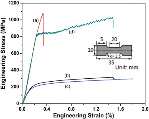
Free-standing 20-µm-thick deposits can be mechanically stripped off the 304 stainless steel substrates and processed into tensile specimens as shown in by wire-electrode cutting. But mechanical testing of the free-standing films is difficult to perform due to the shear stress. The samples break quickly and the engineering strain is less than 0.4%. However, the soft substrates can stabilize the specimens and avoid strain localization during tensile tests.[Citation26–28] As the samples were tested together with the 304 stainless steel substrates, ductility is not only a function of the film microstructure, but is also dependent on the overall adhesion of the substrate. shows the typical tensile engineering stress–strain curve for the free-standing sample (curve a) in comparison with that for the sample together with the substrate (curve b) and the 304 stainless steel substrate (curve c) under a tensile rate of 0.5 mm/min. There is no synergetic and destructive interaction between the deposits and the substrate, so that the stress in the deposit layer (curve d) can be estimated by the rule of mixture (ROM) [Citation29]:
(1)
where σdeposit is the calculated stress of the deposit, σtotal is the measured stress of the deposit together with substrate, σsubstrate is the measured stress of the substrate without deposit and Vdeposit is the volume fraction of the deposit layer. As the 20-µm thick Co-Ni alloys deposited on a 0.5-mm thick 304 stainless steel substrate, the value of Vdeposit is about 0.04. The elastic modulus of the deposit layer estimated by ROM is well in agreement with the measured value of the free-standing sample. Results show that the fracture strain of the sample with substrate is more than four times larger than that of the free-standing sample, while the fracture stress of the sample with substrate is smaller than that of the free-standing sample. Samples after tensile tests are collected for the next morphology observation. Disks of 3 mm diameter were punched for TEM observation.
Figure 3. Typical tensile engineering stress–strain curves under a tensile rate of 0.5 mm/min: (a) free-standing sample; (b) sample together with substrate; (c) 304 stainless steel substrate and (d) curve of deposit layer estimated by ROM. The inset shows the geometry of tensile samples (R, radius of curvature).
3.3. Microstructure of Co-Ni Alloys after Tensile Tests
shows the bright-field TEM images of Co-31.0at%Ni after different tensile tests. Five samples after tensile tests are collected for the morphology observation: (a) free-standing sample after tensile failure up to = 0.35%; (b), (c) and (d) samples with substrates after tensile tests stop when
= 0.6%,
= 1.0% and
= 1.4%; (e) sample with substrate after tensile failure up to
= 1.5%. The nanocrystalline structure with hcp phase remains unchanged in samples (a), (b) and (c). Just tiny amounts of grains began to grow when
= 1.4% ((d)), and more grains began to grow after tensile failure up to
= 1.5% ((e)). As shown in , the background nano grains remain the hcp phase ((c)), while an fcc nano-twinned structure is formed instead of the initial hcp phase in the grown grains ((d)). Our previous studies [Citation16] have reported that the nano-twinned fcc structure has an extraordinary stability within the temperature range from 4.2 to 1,000 K, and that the fcc phase will not transform back to the hcp phase. The formation of the fcc phase is also confirmed by XRD pattern ((e)). The microstructures of all Co-20.6at%Ni and Co-48.0at%Ni samples remain unchanged after tensile tests, and are similar to the images shown in , hence are not shown here.
Figure 4. Bight-field TEM images of Co-31.0at%Ni after different tensile tests: (a) = 0.35% (free-standing sample); (b)
= 0.6%; (c)
= 1.0%; (d)
= 1.4% and (e)
= 1.5%.
Figure 5. Structure of Co-31.0at%Ni samples after tensile failure up to = 1.5%: (a) overall bright-field image; (b) bright-field image of the grown grains; (c) SAED pattern corresponding to the background; (d) SAED pattern corresponding to the grains grown up, which is measured by nano-beam diffraction (NBD) model and (e) X-ray diffraction pattern.
4. Discussions
It is well known that the reversible fcc to hcp transformation exhibits a negligible volume change.[Citation30] The high degree of structural similarity between the two phases implies small entropy and enthalpy changes. Co-Ni alloys have low stacking fault energy with an approximate value of 31 and 18.5 kJ/m2 for the hcp and fcc structures in pure Co, respectively.[Citation31] Thus, the conversion between the two structures easily occurs via stacking fault formation.[Citation32] These characteristics result in easier phase transformation in Co-Ni alloys [Citation33] and provide the possibility of strain-induced phase transformation from hcp to fcc.
As shown in , the reverse martensitic transformation from hcp to fcc in coarse-grained Co-31.0at%Ni alloy takes place at about 420 K. However, it happens at room temperature together with grain growth in electrodeposited nanocrystalline Co-31.0at%Ni sample under tension. The unusual strain-induced reverse transformation shows a close relationship with the grain growth.
The high interfacial volume fraction in the nanocrystalline materials leads to significant driving forces for coarsening,[Citation34] and there is a huge tendency for grain growth, especially at elevated temperatures. The strain energy provides a kind of driving force that the grain growth could occur during the deformation process. Strain-induced grain growth has been extensively studied in nanocrystalline materials and it is reported that there is a critical value of stress above which deformation-induced grain growth would occur.[Citation21,Citation22] However in the present study, grain growth during tensile test occurred only in the Co-31.0at%Ni with ε higher than 1.4%. Based on the engineering stress–strain curves shown in , it is suggested that the grain growth was induced by sufficient strain rather than stress.
On the one hand, exothermic heat resulting from grain growth can promote reverse transformation. As shown in , the thermodynamic phase equilibrium temperature (T0) of the hcp and fcc phases for Co-31.0at%Ni is higher than room temperature, at which the free energies of the two phases are equal. It means that the phase transformation from hcp to fcc should not take place at room temperature unless there are other energies which can provide an additional driving force, that is, increasing the instant temperature for the sample. The resources of the extra energies may be provided by the thermal effect of the deformation process and grain growth.
We can estimate the temperature rise in the deformation process using the following equation [Citation35]:
(2)
where β = 0.9 (assuming 90% of work of deformation was converted to heat), ρ is the density of the sample and CV is the specific heat capacity. The specific heat capacity of Co-31at%Ni and 304 stainless steel at room temperature is about 0.44 J/(g·K) [Citation36] and 0.50 J/(g·K),[Citation37] respectively. As
= 1.4%, ΔΤ of the 304 stainless steel substrate is about 1 K and ΔΤ of Co-31at%Ni deposit layer is about 4 K. It means that the heat generated from the deformation process can be ignored.
Also, we can estimate the temperature rise in the grain growth process by measuring the heat evolution using DSC. The released heat can be estimated by calculating the area of exothermic peak. When the grains with an initial size of 15 nm grow up to about 300 nm,[Citation16,Citation17] the released heat is about 31 J/g. As the grain has grown up to about 150 nm after tension ((b)), we can use 31 J/g as the value of released heat for estimation. Whereas the specific heat of Co-31at%Ni alloy is about 0.44 J/(g·K), the heat evolution may increase the temperature by about 70°, so that the temperature can reach T0 and the reverse transformation can occur in Co-31.0at%Ni. This estimate is based on two assumptions. First, almost all the grains have grown up during heating, which is confirmed in our previous studies.[Citation16,Citation17] Second, the velocity of the phase transformation is quite rapid that the released heat of the localized grain growth has no time for dissipation, and then, when the extra heat diffuses to the whole specimen including substrate, there is no obvious temperature rise.
Meanwhile, it can be reasonably deduced that the grain boundary movement should occur more easily because of the high mobility of atoms during the phase transformation.[Citation38] Omori et al. [Citation39] reported an abnormal grain growth induced by cyclic heat treatment between a high-temperature single-phase region and a lower temperature two-phase region, and pointed out that the abnormal grain growth phenomenon results from the formation of a sub-grain structure introduced through phase transformation. As a consequence, we assume that the grain growth process in nanocrystalline Co-Ni alloys could be enhanced by phase transformation. Since the temperature for phase transformation from hcp to fcc in Co-20.6at%Ni is much higher than room temperature and the initial crystal structure of the as-deposited Co-48.0at%Ni is fcc, no phase transformation will happen in these samples. As a result, grain growth has not been observed in Co-20.6at%Ni and Co-48.0at%Ni after tensile tests. The compositional dependent behaviors imply that the grain growth and the phase transformation from hcp to fcc at an appropriate transformation temperature can take place in the samples during tensile tests with a value of engineering strain about 1.4%. A much larger strain may be necessary to induce grain growth in samples without a phase transformation.
From what has been discussed in this paper, it is a mutual promotion process that the phase transformation from hcp to fcc always takes place coupled with grain growth in nanocrystalline Co-Ni alloys. Our previous studies [Citation16] have reported that the symbiotic transformation happens at about 600 K upon heating in electrodeposited nanocrystalline Co-Ni alloys, which is little relevant with the composition. However in the present study, we observe such symbiotic process during tensile tests performed at room temperature in electrodeposited nanocrystalline Co-31.0at%Ni. It is suggested that the symbiotic transformation can be triggered by a sufficiently high temperature or a sufficient applied strain. We can forecast that the strain-induced reverse transformation can be observed in nanocrystalline Co-Ni alloys with other components after tensile tests performed near the As temperature. More experiments of nanocrystalline Co-Ni alloys with different components at different temperatures would be carried out for verification.
5. Conclusion
In summary, strain-induced reverse phase transformation from hcp to fcc in nanocrystalline Co-31.0at%Ni alloy was observed. Close relationship and conditions between the reverse phase transformation and grain growth during tensile test were confirmed based on the detail observations on Co-20.6at%Ni, Co-31.0at%Ni and Co-48.0at%Ni. It is suggested that the mutual promotion process of the reverse phase transformation coupled with grain growth can be triggered by a sufficiently high temperature or a sufficient applied strain.
Acknowledgement
This work is supported by the National Natural Science Foundation of China (No. 51174251, No. 51201100 and No. 51201105) and 973 Program (No. 2011CB706604). Authors thank Dr. K. Zhang, University of Shanghai for Science and Technology, for assistance with the TEM observation.
Disclosure Statement
No potential conflict of interest was reported by the authors.
References
- Pineau A, Pelloux R. Influence of strain-induced martensitic transformations on fatigue crack growth rates in stainless steels. Metall Trans. 1974;5(5):1103–1112. doi: 10.1007/BF02644322
- Otsuka K, Wayman CM. Shape memory materials. Cambridge: Cambridge University Press; 1998.
- Gleiter H. Nanocrystalline materials. Prog Mater Sci. 1989;33(4):223–315. doi: 10.1016/0079-6425(89)90001-7
- Suryanarayana C. Nanocrystalline materials. Int Mater Rev. 1995;40(2):41–64. doi: 10.1179/imr.1995.40.2.41
- Lu K. Nanocrystalline metals crystallized from amorphous solids: nanocrystallization, structure, and properties. Mater Sci Eng R. 1996;16(4):161–221. doi: 10.1016/0927-796X(95)00187-5
- Huang JY, Wu YK, Ye HQ, Lu K. Allotropic transformation of cobalt induced by ball milling. Nanostruct Mater. 1995;6(5):723–726. doi: 10.1016/0965-9773(95)00160-3
- Sort J, Nogués J, Suriñach S, Baró MD. Microstructural aspects of the hcp-fcc allotropic phase transformation induced in cobalt by ball milling. Philos Mag. 2003;83(4):439–455. doi: 10.1080/0141861021000047159
- Wu X, Tao N, Hong Y, Liu G, Xu B, Lu J, Lu K. Strain-induced grain refinement of cobalt during surface mechanical attrition treatment. Acta Mater. 2005;53(3):681–691. doi: 10.1016/j.actamat.2004.10.021
- Wu X, Tao N, Hong Y, Lu J, Lu K. γ→ martensite transformation and twinning deformation in fcc cobalt during surface mechanical attrition treatment. Scr Mater. 2005;52(7):547–551. doi: 10.1016/j.scriptamat.2004.12.004
- Edalati K, Toh S, Arita M, Watanabe M, Horita Z. High-pressure torsion of pure cobalt: hcp-fcc phase transformations and twinning during severe plastic deformation. Appl Phys Lett. 2013;102(18):181902-1–181902-4. doi: 10.1063/1.4804273
- Sort J, Zhilyaev A, Zielinska M, Nogués J, Surinach S, Thibault J, Baró MD. Microstructural effects and large microhardness in cobalt processed by high pressure torsion consolidation of ball milled powders. Acta Mater. 2003;51(20):6385–6393. doi: 10.1016/j.actamat.2003.08.006
- Nishizawa T, Ishida K. The Co-Ni (Cobalt-Nickel) system. Bull Alloy Phase Diagr. 1983;4(4):390–395. doi: 10.1007/BF02868090
- Takeuchi S, Honma T. Studies on the β→ transformation in Cobalt-Nickel alloys. I: Propagation process of the transformation. Sci Rep Res Inst Tohoku Univ. 1957;A9:492–507.
- Postnikov VS, Belko VN, Sharshakov IM. Temperature-dependence of internal friction in Cobalt-Nickel alloys. Fiz Met Metalloved. 1968;26(6):1051–1056.
- Remy L, Pineau A. Twinning and strain-induced fcc → hcp transformation on the mechanical properties of Co-Ni-Cr-Mo alloys. Mater Sci Eng. 1976;26(1):123–132. doi: 10.1016/0025-5416(76)90234-2
- Li JY, Ni C, Liu JY, Jin MJ, Li W, Jin XJ. Extraordinary stability of nano-twinned structure formed during phase transformation coupled with grain growth in electrodeposited Co-Ni alloys. Mater Chem Phys. 2014;148(3):1202–1211. doi: 10.1016/j.matchemphys.2014.09.048
- Li J, Liu J, Jin M, Jin X. Grain size dependent phase stability of pulse electrodeposited nano-grained Co–Ni films. J Alloys Compd. 2013;577:S151–S154. doi: 10.1016/j.jallcom.2012.02.002
- Zhang K, Weertman JR, Eastman JA. Rapid stress-driven grain coarsening in nanocrystalline Cu at ambient and cryogenic temperatures. Appl Phys Lett. 2005;87(6):061921-1–061921-3.
- Jin M, Minor AM, Stach EA, Morris Jr JW. Direct observation of deformation-induced grain growth during the nanoindentation of ultrafine-grained Al at room temperature. Acta Mater. 2004;52(18):5381–5387. doi: 10.1016/j.actamat.2004.07.044
- Wen H, Zhao Y, Li Y, Ertorer O, Nesterov KM, Islamgaliev RK, Valievb RZ, Lavernia EJ. High-pressure torsion-induced grain growth and detwinning in cryomilled Cu powders. Philos Mag. 2010;90(34):4541–4550. doi: 10.1080/14786435.2010.514579
- Liao XZ, Kilmametov AR, Valiev RZ, Gao H, Li X, Mukherjee AK, Bingert JF, Zhu YT. High-pressure torsion-induced grain growth in electrodeposited nanocrystalline Ni. Appl Phys Lett. 2006;88(2):021909-1–021909-3. doi: 10.1063/1.2159088
- Zhang Y, Sharon JA, Hu GL, Ramesh KT, Hemker KJ. Stress-driven grain growth in ultrafine grained Mg thin film. Scr Mater. 2013;68(6):424–427. doi: 10.1016/j.scriptamat.2012.11.013
- Gianola DS, Van Petegem S, Legros M, Brandstetter S, Van Swygenhoven H, Hemker KJ. Stress-assisted discontinuous grain growth and its effect on the deformation behavior of nanocrystalline aluminum thin films. Acta Mater. 2006;54(8):2253–2263. doi: 10.1016/j.actamat.2006.01.023
- Fan GJ, Fu LF, Qiao DC, Choo H, Liaw PK, Browning ND. Grain growth in a bulk nanocrystalline Co alloy during tensile plastic deformation. Scr Mater. 2006;54(12):2137–2141. doi: 10.1016/j.scriptamat.2006.02.041
- El-Sherik AM, Erb U. Synthesis of bulk nanocrystalline nickel by pulsed electrodeposition. J Mater Sci. 1995;30(22):5743–5749. doi: 10.1007/BF00356715
- Kobler A, Lohmiller J, Schäfer J, Kerber M, Castrup A, Kashiwar A, Horst H, Kübel C. Deformation-induced grain growth and twinning in nanocrystalline palladium thin films. Beilstein J Nanotechnol. 2013;4(1):554–566. doi: 10.3762/bjnano.4.64
- Lohmiller J, Woo NC, Spolenak R. Microstructure–property relationship in highly ductile Au–Cu thin films for flexible electronics. Mater Sci Eng A. 2010;527(29):7731–7740. doi: 10.1016/j.msea.2010.08.043
- Hommel M, Kraft O. Deformation behavior of thin copper films on deformable substrates. Acta Mater. 2001;49(19):3935–3947. doi: 10.1016/S1359-6454(01)00293-2
- Wu XL, Jiang P, Chen L, Zhang JF, Yuan FP, Zhu YT. Synergetic strengthening by gradient structure. Mater Res Letts. 2014;2(4):185–191. doi: 10.1080/21663831.2014.935821
- Taylor A. Latice parameters of binary nickel cobalt alloys. J Inst Met. 1950;77:585–594.
- Betteridge W. The properties of metallic cobalt. Prog Mater Sci. 1980;24:51–142. doi: 10.1016/0079-6425(79)90004-5
- Hsu TY. Thermodynamic properties of β(γ)→ martensitic transformation. Acta Metall Sin. 1980;16:430–434.
- Liu Y, Yang H, Tan G, Miyazaki S, Jiang B, Liu Y. Stress-induced FCC ↔ HCP martensitic transformation in CoNi. J Alloys Compd. 2004;368(1):157. doi: 10.1016/j.jallcom.2003.07.015
- Wang N, Wang Z, Aust KT, Erb U. Isokinetic analysis of nanocrystalline nickel electrodeposits upon annealing. Acta Mater. 1997;45(4):1655–1669. doi: 10.1016/S1359-6454(96)00254-6
- Mishra A, Kad BK, Gregori F, Meyers MA. Microstructural evolution in copper subjected to severe plastic deformation: experiments and analysis. Acta Mater. 2007;55(1):13–28. doi: 10.1016/j.actamat.2006.07.008
- Barin I. Thermochemical data of pure substances. Weinheim: VCH; 1995.
- Xavior MA, Adithan M. Determining the influence of cutting fluids on tool wear and surface roughness during turning of AISI 304 austenitic stainless steel. J Mater Process Tech. 2009;209(2):900–909. doi: 10.1016/j.jmatprotec.2008.02.068
- Ding X, Liu X. Correlation between anatase-to-rutile transformation and grain growth in nanocrystalline titania powders. J Mater Res. 1998;13(9):2556–2559. doi: 10.1557/JMR.1998.0356
- Omori T, Kusama T, Kawata S, Ohnuma I, Sutou Y, Araki Y, Ishida K, Kainuma R. Abnormal grain growth induced by cyclic heat treatment. Science. 2013;341(6153):1500–1502. doi: 10.1126/science.1238017