
 ?Mathematical formulae have been encoded as MathML and are displayed in this HTML version using MathJax in order to improve their display. Uncheck the box to turn MathJax off. This feature requires Javascript. Click on a formula to zoom.
ABSTRACT
As demonstrated by the loading–unloading tests and the modeling of the grain size effect and the composite effect, mainly owing to the back stress induced by CNTs, carbon nanotube/aluminum (CNT/Al) composites exhibit higher strain hardening capability than the unreinforced ultrafine-grained Al matrix. The back stress induced by CNTs should arise from the interfacial image force and the long-range interaction between statically stored dislocations and geometrically necessary dislocations around the CNT/Al interface. Therefore, this CNT-induced interfacial back stress strengthening mechanism is supposed to provide a novel route to enhancing the strain hardening capability and ductility in CNT/Al composites.
IMPACT STATEMENT
The present work investigates the roles and origins of back stress in the strain hardening of the carbon nanotubes/aluminum composites for the first time.
GRAPHICAL ABSTRACT
Carbon nanotube/aluminum (CNT/Al) composites have emerged as a novel and potential kind of metal matrix composites (MMCs), as they exhibit high specific stiffness, strength and good plasticity [Citation1]. It has been generally accepted that the intrinsic properties of both CNTs and Al and the impacts of CNTs on the microstructure of Al matrix determine the mechanical properties of CNT/Al composites simultaneously [Citation1]. For example, according to George et al. [Citation2], Nam et al. [Citation3] and Mokdad et al. [Citation4], the yield strength of CNT/Al composites is considered to be determined by the effective stress transfer to CNTs, grain size (Hall-Petch effect), thermal mismatch dislocations and Orowan mechanism in the Al matrix. However, the plastic deformation mechanisms of CNT/Al composites, being crucial for their ductility and toughness, haven't been fully understood yet.
An important but rarely discussed issue about plastic deformation of CNT/Al composites is their strain hardening (work hardening) capability. The CNT/Al composites usually exhibit high failure strain but low uniform elongation (strain before necking) [Citation1]. It is mainly due to the lack of dislocation accumulation capability in the ultrafine-grained (UFG) matrix (grain size < 1 µm), which weakens the strain hardening capability and thus results in the early necking or strain localization [Citation5,Citation6]. According to the Considère criterion [Citation7], which is governing the onset of necking,
(1)
(1)
where
is the true stress and
is the true strain, higher strain hardening capability could help to delay necking and give rise to the uniform elongation. Only a few efforts have been made in the investigation of CNT/Al composites’ strain hardening behaviors. Yoo et al. [Citation8] reported that CNTs homogenously dispersed inside Al grains could contribute to strain hardening capability by the Orowan mechanism. However, in most cases, CNTs located at Al grain boundaries [Citation1]. Dong et al. [Citation9,Citation10] developed a dislocation density based model and estimated that the elastic mismatch between CNTs and Al would be favorable to the strain hardening capability through the interaction between geometrically-necessary dislocations (GNDs) and statistically stored dislocations (SSDs). However, no direct experimental evidence was provided.
On the other hand, the strain hardening behaviors of polycrystalline metals, dispersoid strengthening alloys and conventional MMCs have been extensively discussed. Strain hardening results from the dynamic interactions of dislocations with each other and with the various constituents of the microstructure, e.g. forest dislocations, grain boundaries and second phases [Citation11–14]. The dislocation storage processes give rise to both the non-directional effective stress required locally for the dislocations to move (short-range interactions like friction stress and forest dislocation hardening) and the directional back stress associated with the microstructures providing long-range interactions with mobile dislocations [Citation12]. In previous models of the tensile deformation of CNT reinforced MMCs [Citation9,Citation10], the forest hardening mechanism has been considered. However, to the best of our knowledge, there weren't any experimental investigation and discussion on the role of back stress.
The aim of the present work is to discuss the tensile strain hardening behaviors of CNT/Al composites in terms of the effective and back stresses. The evolution of these two components of tensile flow stress is investigated with the loading–unloading tests, and the roles of CNT-induced back stresses are modeled and quantitatively analyzed. Besides, GND maps in CNT/Al composites achieved with automated crystal orientation mapping in transmission electron microscope (TEM ACOM) and the potentials of back stress strengthening mechanisms that can be used in the design of CNT/Al composites are also discussed.
A Flake Powder Metallurgy route based on shift-speed ball milling, developed in our previous work [Citation15], was utilized to fabricate 1 vol.% and 2 vol.% CNT/Al composites. The Al samples without CNTs were also fabricated by the same processes. Tensile tests and loading–unloading tests were performed on at a constant strain rate of 6.67 × 10⁻⁴ s−1 (1 mm/min) at room temperature. Details of the fabrication and characterization procedure are provided in Supplementary Material.
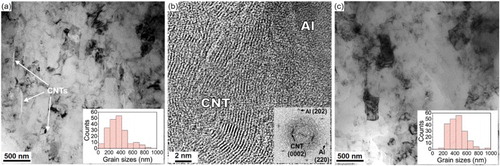
shows the TEM images of the longitudinal section of 2 vol.% CNT/Al composite and Al. The average equivalent grain sizes (equivalent circle diameters) of the Al sample and the 2 vol.% CNT/Al composite sample are ∼418 nm and ∼335 nm, respectively. Also, the CNTs mostly distribute at the intergranular boundaries in the CNT/Al composite. (b) shows the high-resolution TEM (HRTEM) image of the well bonded CNT/Al interface in 2 vol.% CNT/Al composites. The inset fast Fourier transformation (FFT) pattern proves the existence of both Al and CNT lattice fringes without interfacial amorphous C phase. Also, although rarely observed in TEM images, a few carbides are detected in these samples (Supplementary Material), which is in accordance with previous reports [Citation1,Citation15].
Figure 1. (a) TEM image of 2 vol.% CNT/Al composites; (b) HRTEM image of a CNT embedded in Al matrix. The inset figure is the FFT pattern of (b); (c) TEM image of Al.
The typical engineering tensile stress–strain and true stress–strain curves for Al and CNT/Al composites are shown in (a,b). The tensile strength of the Al sample, 1 vol.% CNT/Al composite sample and 2 vol.% CNT/Al composite sample is 228 MPa, 266 MPa, 332 MPa, with the corresponding uniform elongation of 5.2%, 5.6% and 5.3%, respectively. CNT strengthened Al without sacrificing the uniform elongation ((b)). The strengthening effect should be due to the coupling of grain refinement, dislocations and the load-transfer effects. More details of the mechanical properties are shown in Table S1. The strain hardening rate, Θ, is defined by,
(2)
(2)
Figure 2. (a) Engineering tensile stress–strain curves, (b) true stress–strain curves and (c) strain hardening rate curves of Al and CNT/Al composites.
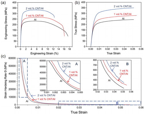
As shown in (c), the Θ of CNT/Al before the true strain of 0.015 are obviously higher than that of Al and increase with the increase of CNT content (Inset A). After the true strain of 0.02, the difference in the Θ of Al and CNT/Al composites become much smaller but should contribute to the uniform elongation according to the Considère criterion. (Inset B).
The variation of Θ depends on the variation of flow stress. To clarify the origins of the flow stress, the loading–unloading tests [Citation12,Citation16] ((a)) were performed to estimate effective and back stresses. CNT/Al composites show strong Bauschinger effect: during unloading, the reverse plastic flow starts even when the applied stress is still in tension. The methodology of estimation of back and effective stress from the loading–unloading curves have been extensively discussed in the past by different authors [Citation12,Citation13]. As defined in (b), the effective stress (σeff) and back stress (σb) can be calculated as,
(3)
(3)
(4)
(4)
where σu is the unloading yield stress and σ* is the thermal part of the flow stress. Some details of the calculation are described in Supplementary Material.
Figure 3. (a) Loading–unloading curves of CNT/Al composites and Al; (b) Schematic of calculating effective and back stresses; (c∼e) effective, back and flow stresses at different strain in Al, 1vol.% and 2 vol. % CNT/Al composites, respectively.
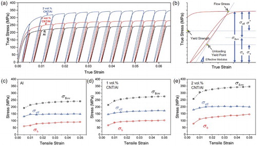
As shown in (c–e), both effective and back stresses increased with the addition of CNT in Al, resulting in the strengthening of the composites. The increasing rates of the effective stress of 1 vol.% and 2 vol.% CNT/Al and Al are similar at different strain, while the pronounced increase of increasing rate of back stress could be observed in CNT/Al composites than Al, especially in 2 vol.% CNT/Al composites. Thus, the increase of back stress contributes to the higher strain hardening rates of CNT/Al composites than Al.
Effective stress is from the non-directional short-range local stress for a dislocation to move, like the friction stress of Al and the short-range interaction between forest and mobile dislocations [Citation12]. In addition to the internal dislocation storage process of Al matrices, the GNDs induced by the deformation incompatibility between CNT and Al could contribute to the effective stress through dislocation strengthening [Citation10].
Back stress is from the directional long-range internal stress resulting from the elastic loading of the ‘hard zones’ [Citation17,Citation18]. During mechanical loading, extra loads will be transferred from the soft zones to the hard zones, and the corresponding counterforces in the soft zone must be balanced by lattice strain and dislocations. These dislocations provide long-range interactions with mobile dislocations, exert directional back stress.
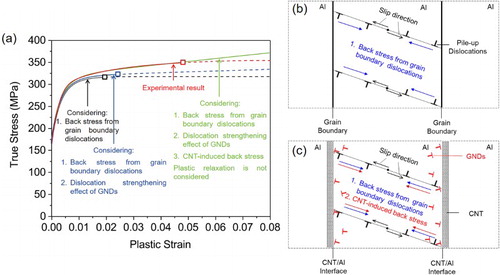
Different kinds of microstructures, e.g. grain boundaries and the second phases, could act as the ‘hard zone’. First, the pile-up dislocations stopped at grain boundaries could cause a back stress to develop impeding the progress of similar dislocations [Citation19], as shown in (b). Then the net long-range stresses will be reduced when dislocations of opposite sign arrive at the boundary in adjacent grains or on other slip systems thereby screening the stress field from the dislocations already at the boundary [Citation14]. Finer grains could accelerate both the increasing rate of back stress and the screening effect. The addition of CNTs leads to the refinement of Al grains, which should be one of the origins of the evolution of back stress.
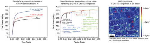
Figure 4. (a) Theoretical and experimental stress–strain curves of 2 vol.% CNT/Al composites. The symbols □ mark the start points of necking determined by the Considère criterion, the solid lines are the stress–strain curves of the strain hardening stage and the dashed lines are the stress–strain curves of the necking stages. (b) and (c) Illustration of the origin of grain boundary back stress and CNT-induced back stress (image force and GNDs).
Second, the hard, non-deformable second phases exert back stress through the elastic constraint of the plastic flow. According to Brown and Clarke [Citation20], it is simply proportional to the volume fraction of the second phases and to the applied plastic strain. When the local stress at a second phase exceeds a threshold, it can cause plastic relaxation, with the activation of the secondary slip and the buildup of dislocation forest. Plastic relaxation may lead to the partial release of the loads in the second phases and the global back stress.
To quantificationally analyze the origins of the role of effective and back stress, a model based on the above analysis is used to estimate the stress–strain relationship of CNT/Al composites. The flow stress, , can be expressed as:
(5)
(5)
where the first term is the friction stress of Al, the second term is the Hall-Petch relationship describing grain boundary strengthening, the third term is the Taylor relationship describing dislocation strengthening, the fourth term is the load transferred to CNTs at yield point, the fifth and sixth terms are the back stresses induced by grain boundary dislocations [Citation14] and reinforcements [Citation20] (namely CNTs), respectively, and the last term is the influence of plastic relaxation. The definitions of each parameter are listed in Table S1. Detailed discussions on this model and its reliability are shown in Supplementary Material.
(a) shows the estimated true stress-plastic strain curves of 2 vol.% CNT/Al composites with or without considering the dislocation strengthening effect of GNDs, the CNT-induced back stress and the plastic relaxation. Also, the true stress-plastic strain curves of Al fit well with the Al samples, as shown in Figure S1. The stress–strain curves estimated from Equation (6) without considering plastic relaxation fit well with the experimental results before the necking points. It can be seen that the back stress from grain boundary dislocations contributes to a major part of the flow stress of the composites, as well as the high strain hardening rate of CNT/Al composites before 1% strain. Both the dislocation hardening effect of GNDs and the CNT-induced back stress give rise to the strain hardening capabilities and uniform elongations of CNT/Al composites, while the contribution of CNT-induced back stress is more pronounced. The average stresses in CNTs, , should be equilibrium with the strengthening effects in the yield strength and CNT-induced back stress, namely,
(6)
(6)
At the uniform elongation strain of the 2 vol.% CNT/Al composites, the average stresses in CNTs are over 2 GPa. Such high stress may result in pronounced plastic relaxation or even local failure in the near-interface regions and thus lead to the deviation from the estimated curves. The plastic relaxation process is complex as it is influenced by the interface conditions, local lattice orientations, local dislocation structures and else factors. It's hard to be quantified with the present model but could be qualitatively analyzed by comparing the theoretical and experimental results.
It should be noticed that the CNT-induced back stress in Equation (6) is derived based on the Eshelby's theory of elastic inclusions, which is not directly connected with the dislocations behaviors. The shear-resistant, intragranular nano second phases could trap Orowan loops and exert back stress, which has been extensively discussed in Al alloys [Citation21,Citation22]. However, as shown in (a), as the CNTs distribute mostly at grain boundaries, they should not give rise to back stress by trapping Orowan loops. On the other hand, interfaces could apply the long-range ‘image force’ to the near-by pile-up dislocations due to the difference in the shear modulus of the two phases [Citation23], which should also contribute the CNT-induced back stress ((b)). Another origin of CNT-induced back stress may be the CNT-induced GNDs ((b)). As the stiff CNTs and the matrices would deform incompatibly, shear strain gradient would be built up and the lattice would become curved, leading to the accumulation of a kind of GNDs defined by Nye [Citation24]. As those GNDs are constrained by the near-interface strain gradients, they could provide long-range interaction with the SSDs and give rise to back stress at macroscopic.
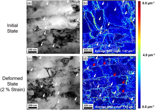
provides the existence of this kind of GNDs. (a,c) shows the TEM images of 2 vol.% CNT/Al composites at zero strain and 2% strain. 2% strain is chosen because at this strain the CNT-induced GNDs are detectable and less influenced by the GNDs induced due to the incompatible deformation of different grains. (b,d) are the corresponding GND maps estimated with TEM ACOM and the Nye tensor. It could be observed that in CNT/Al composites at zero strain, the GND-rich regions are mostly located near grain boundaries or in some nearly vertical bands. Those bands should be a kind of intragranular boundaries, referred as the geometrically-necessary boundaries, similar to the subgrain boundaries [Citation25,Citation26]. After 2% strain, much more GND-rich regions are located around CNTs. Also, the average GND values increase from 1.67 µm−1 to 1.97 µm−1 after 2% strain. Thus, the generation of most GNDs in deformed CNT/Al composites prove to be associated with CNTs.
Figure 5. (a) TEM image of 2 vol.% CNT/Al at zero strain; (b) corresponding GND map of (a); (c) TEM image of 2 vol.% CNT/Al at 2% strain; (d) corresponding GND map of (c); The write arrows point the CNTs and red arrows point the CNT-free grain boundaries. Slight distortions of the GND maps from TEM images originate from an inclination of 55° of the off-axis acquisition camera.
As the elastic loading of CNTs, the near-interface strain gradients and GND accumulation are structure-sensitive [Citation13,Citation27], it is potential to improve the strain hardening capability and uniform elongation of CNT/Al composites through well-designed architectures. For example, the CNT/Al composites with nanolaminated [Citation28] and dual-matrix [Citation29] architecture exhibited superior balance in strength and ductility compared with those with disorder structures. Back stress strengthening exerted by GNDs is supposed to be an important mechanism for the well balanced comprehensive mechanical properties. Similar back stress induced Θ increase was also reported in gradient structured interstitial-free steels [Citation13] and heterogeneous lamella structured Ti [Citation16]. Thus, further investigation on the correlation between the architecture and back stress strengthening is possible to provide routes towards superior ductility in CNT/Al composites.
In conclusion, it is found that the CNT/Al composites exhibit higher strain hardening capability than the unreinforced UFG Al matrix, which results in the strength enhancement of CNT/Al composites without sacrificing the uniform elongations. The loading–unloading tests reveal that, instead of the effective stress, it is the increased back stress that is responsible for the higher strain hardening capability in CNT/Al composites than Al. Using a strain hardening model considering the contribution of grain boundary and CNT/Al interfaces, it is found that the CNT-induced interfacial back stress contributes primarily to the extra strain hardening in CNT/Al composites. Such CNT-induced back stress should be exerted by the interfacial image force and the long-range interaction between SSDs and GNDs around the CNT/Al interface. From this point of view, proper interface and architecture design is supposed to be a possible route to preparing CNT/Al composites with desirable strain hardening capability, strength and ductility through the interfacial back stress strengthening mechanism.
Supplement_Material
Download MS Word (1.5 MB)Disclosure statement
No potential conflict of interest was reported by the authors.
Additional information
Funding
Related Research Data
References
- Tjong SC. Recent progress in the development and properties of novel metal matrix nanocomposites reinforced with carbon nanotubes and graphene nanosheets. Mater Sci Eng R Rep. 2013;74(10):281–350. doi: 10.1016/j.mser.2013.08.001
- George R, Kashyap KT, Rahul R, et al. Strengthening in carbon nanotube/aluminium (CNT/Al) composites. Scr Mater. 2005;53(10):1159–1163. doi: 10.1016/j.scriptamat.2005.07.022
- Nam DH, Cha SI, Lim BK, et al. Synergistic strengthening by load transfer mechanism and grain refinement of CNT/Al–Cu composites. Carbon N Y. 2012;50(7):2417–2423. doi: 10.1016/j.carbon.2012.01.058
- Mokdad F, Chen D, Liu Z, et al. Deformation and strengthening mechanisms of a carbon nanotube reinforced aluminum composite. Carbon N Y. 2016;104:64–77. doi: 10.1016/j.carbon.2016.03.038
- Wang Y, Chen M, Zhou F, et al. High tensile ductility in a nanostructured metal. Nature. 2002;419(6910):912–915. doi: 10.1038/nature01133
- Zhu YT, Liao X. Nanostructured metals: retaining ductility. Nat Mater. 2004;3(6):351–352. doi: 10.1038/nmat1141
- Dieter GE. Mechanical metallurgy, SI metric edition. London: McGraw-Hill; 1988.
- Yoo S, Han S, Kim W. Strength and strain hardening of aluminum matrix composites with randomly dispersed nanometer-length fragmented carbon nanotubes. Scr Mater. 2013;68(9):711–714. doi: 10.1016/j.scriptamat.2013.01.013
- Dong S, Zhou J, Hui D. A quantitative understanding on the mechanical behaviors of carbon nanotube reinforced nano/ultrafine-grained composites. Int J Mech Sci. 2015;101–102:29–37. doi: 10.1016/j.ijmecsci.2015.07.019
- Dong S, Zhou J, Hui D, et al. Size dependent strengthening mechanisms in carbon nanotube reinforced metal matrix composites. Compos A: Appl Sci Manuf. 2015;68:356–364. doi: 10.1016/j.compositesa.2014.10.018
- Fribourg G, Bréchet Y, Deschamps A, et al. Microstructure-based modelling of isotropic and kinematic strain hardening in a precipitation-hardened aluminium alloy. Acta Mater. 2011;59(9):3621–3635. doi: 10.1016/j.actamat.2011.02.035
- Feaugas X. On the origin of the tensile flow stress in the stainless steel AISI 316L at 300 K: back stress and effective stress. Acta Mater. 1999;47(13):3617–3632. doi: 10.1016/S1359-6454(99)00222-0
- Yang M, Pan Y, Yuan F, et al. Back stress strengthening and strain hardening in gradient structure. Mater Res Lett. 2016;4(3):145–151. doi: 10.1080/21663831.2016.1153004
- Delince M, Brechet Y, Embury JD, et al. Structure-property optimization of ultrafine-grained dual-phase steels using a micro structure-based strain hardening model. Acta Mater. 2007;55(7):2337–2350. doi: 10.1016/j.actamat.2006.11.029
- Xu R, Tan Z, Xiong D, et al. Balanced strength and ductility in CNT/Al composites achieved by flake powder metallurgy via shift-speed ball milling. Compos A: Appl Sci Manuf. 2017;96:57–66. doi: 10.1016/j.compositesa.2017.02.017
- Wu X, Yang M, Yuan F, et al. Heterogeneous lamella structure unites ultrafine-grain strength with coarse-grain ductility. Proc Natl Acad Sci U S A. 2015;112(47):14501–14505. doi: 10.1073/pnas.1517193112
- Withers P, Stobbs W, Pedersen O. The application of the Eshelby method of internal stress determination to short fibre metal matrix composites. Acta Metall. 1989;37(11):3061–3084. doi: 10.1016/0001-6160(89)90341-6
- Feaugas X, Haddou H. Effects of grain size on dislocation organization and internal stresses developed under tensile loading in FCC metals. Philos Mag. 2007;87(7):989–1018. doi: 10.1080/14786430601019441
- Sinclair C, Poole W, Bréchet Y. A model for the grain size dependent work hardening of copper. Scr Mater. 2006;55(8):739–742. doi: 10.1016/j.scriptamat.2006.05.018
- Brown LM, Clarke DR. Work hardening due to internal stresses in composite materials. Acta Metall. 1975;23(7):821–830. doi: 10.1016/0001-6160(75)90198-4
- da Costa Teixeira J, Bourgeois L, Sinclair C, et al. The effect of shear-resistant, plate-shaped precipitates on the work hardening of Al alloys: towards a prediction of the strength–elongation correlation. Acta Mater. 2009;57(20):6075–6089. doi: 10.1016/j.actamat.2009.08.034
- Proudhon H, Poole WJ, Wang X, et al. The role of internal stresses on the plastic deformation of the Al–Mg–Si–Cu alloy AA6111. Philos Mag. 2008;88(5):621–640. doi: 10.1080/14786430801894569
- Beauchamp P, Lepinoux J. Image force on a dislocation in a bcc bicrystal: computer investigation of core effects. Philos Mag A: Phys Condens Matter Struct Defects Mech Prop. 2001;81(5):1187–1205. doi: 10.1080/01418610108214436
- Nan C-W, Clarke D. The influence of particle size and particle fracture on the elastic/plastic deformation of metal matrix composites. Acta Mater. 1996;44(9):3801–3811. doi: 10.1016/1359-6454(96)00008-0
- Kuhlmann-Wilsdorf D, Hansen N. Geometrically necessary, incidental and subgrain boundaries. Scr Metall Mater. 1991;25(7):1557–1562. doi: 10.1016/0956-716X(91)90451-6
- Rezvanian O, Zikry M, Rajendran A. Statistically stored, geometrically necessary and grain boundary dislocation densities: microstructural representation and modelling. Proc R Soc A. 2007;463(2087):2833–2853.
- Ashby M. The deformation of plastically non-homogeneous materials. Philos Mag. 1970;21(170):399–424. doi: 10.1080/14786437008238426
- Jiang L, Li Z, Fan G, et al. Strong and ductile carbon nanotube/aluminum bulk nanolaminated composites with two-dimensional alignment of carbon nanotubes. Scr Mater. 2012;66(6):331–334. doi: 10.1016/j.scriptamat.2011.11.023
- Salama EI, Abbas A, Esawi AM. Preparation and properties of dual-matrix carbon nanotube-reinforced aluminum composites. Compos A: Appl Sci Manuf. 2017;99:84–93. doi: 10.1016/j.compositesa.2017.04.002