
ABSTRACT
Residual stress exists extensively in biological and engineering structures. Here we report that residual stress can be engineered to significantly enhance the strength and ductility of gradient materials. In-situ synchrotron experiments revealed that the strongest strain hardening occurred in the layer with the highest compressive residual stress in a gradient structure. This layer remained elastic longer than adjacent layers during tension, producing high hetero-deformation induced stress to increase strength and enhancing work hardening even after the disappearance of the compressive stress to increase ductility. This finding provides a new paradigm for designing gradient structures for superior mechanical properties.
IMPACT STATEMENT
We show that compressive residual stress layer in SMAT-processed gradient material produces hetero-deformation induced hardening, which played a major role in improving strength and ductility.
GRAPHICAL ABSTRACT
1. Introduction
Residual stress exists almost ubiquitously in nature and man-made engineering materials and structures. The advantage of residual stress has long been recognized and well utilized [Citation1–3]. For example, residual stress plays an important role in the function of bio-systems such as blood vessels [Citation4]. Residual stress is engineered into construction structures such as pre-stressed concrete bridge beams to improve their strength and toughness [Citation5]. For metal components, residual stress is often inevitably introduced into their surface layer during forming, machining and heat treatment [Citation1–3]. The most successful application of residual stress is the introduction of compressive residual stress (CRS) into the surface layer of various components to improve their fatigue life [Citation1,Citation6–8]. CRS has also been reported to improve the fracture toughness of brittle materials such as metallic glass and ceramics [Citation9,Citation10]. However, residual stress could be detrimental if inadvertently introduced into materials [Citation3], leading to instability and even catastrophic failure during service [Citation11,Citation12].
Since its inception in 1927, shot peening has been well studied and has become a standard industrial practice for imparting CRS to improve the fatigue life of metal parts of aircrafts and transportation vehicles [Citation1–3]. However, there has been little knowledge so far as to whether or not such CRS affects the tensile properties such as strength and ductility [Citation13–17]. This is mostly because residual stresses of different types will balance each other internally in a metal component [Citation1,Citation2], so it is generally believed that residual stresses have little, if any, influence on the tensile mechanical behavior and properties. In addition, residual stress can be released during plastic deformation [Citation2], which reinforces the above belief. For example, it has been recently reported that gradient-structured metals produced by surface mechanical attrition treatment (SMAT) possess superior strength and ductility [Citation14,Citation15,Citation18]. SMAT is expected to produce CRS in the sample sub-surface layers [Citation2,Citation6,Citation7,Citation19]. However, due to the above belief, the CRS was not considered in explaining the mechanical behavior of these gradient materials.
Here we report that residual stress played a major role in improving the yield strength and ductility of a gradient-structured (GS) interstitial free (IF) steel produced by SMAT. Synchrotron- based X-ray diffraction (XRD) in-situ tension experiment (see Fig. S1 and Note 1 in Supplementary [Citation20,Citation21]) revealed that the CRS sub-surface layer remained elastic longer than other layers, which resulted in direct strain hardening inside the layer itself as well as significant dislocation hardening and hetero-deformation induced (HDI) hardening in adjacent tensile layers, which resulted in higher yield strength. The HDI hardening is a more accurate description of the extra hardening in heterostructured materials than back-stress hardening [Citation22]. Surprisingly, the CRS left a legacy of high strain hardening in the CRS layer long after the CRS was eliminated during plastic deformation, which helped with increasing ductility.
2. Results and discussion
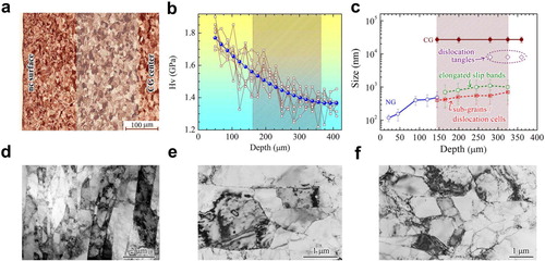
Shown in Figure (a) is the gradient structure (GS) from the nanograined (NG) sample surface layer to coarse-grained (CG) central layer after SMAT processing. A microhardness (Hv) gradient was produced along the depth (Figure (b)). The SMAT processing produced a structural gradient [Citation15,Citation23], as summarized in Figure (c). Dislocation sub-structures were formed in the sequence of elongated slip-bands (Figure (d)), dislocation cells (Figure (e)) and subgrains (Figure (f)), which later evolved into ultrafine-grains and nanograins.
Figure 1. Microstructure and microhardness in a gradient structured (GS) IF steel sample processed by SMAT. a, Cross-sectional morphology of the GS sample, with nanograined (NG) surface layer and central CG layer. b, Microhardness (HV) distribution along the depth. c, Size distribution of grain, subgrain and defect structures along the depth. The features of dislocation sub-structures are shown in d–f, Cross-sectional TEM micrographs showing varying slip-bands, dislocation cells and subgrains at the depth of ∼ 350, 300 and 230 μm, respectively.
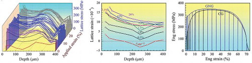
XRD in-situ tensile loading (see Fig. S1) was carried out to measure the stress (elastic strain) and dislocation density evolution in discrete layers along the depth with increasing applied strain (see Figs. S2 and S3 in Supplementary). Figure (a) shows the residual stress distribution along the depth in the as-SMAT-processed sample [Citation6,Citation7]. Figure (b) reveals the evolution of stress in the loading direction along the depth with increasing applied strain. The increase in stress can be considered as an indicator of apparent accumulated strain hardening. As shown, a belly-shaped broad peak was quickly established in the depth range of 150–350 µm with increasing applied tensile strain. This indicates that most strain hardening occurred in this depth range. This range corresponds to the shaded ribbon in Figure (a)–(c). It is obvious that this layer has relatively large grains (Figure (a), (d)–(f)) and medium-to-low microhardness (Figure (b)). It is puzzling why the strongest strain hardening occurred in this depth range. The conventional wisdom is that the strongest strain hardening should occur in the CG central layer where the grain sizes are largest and the initial dislocation density is low.
Figure 2. Experimental results as measured by in-situ XRD synchrotron tensile loading. a, Residual stress distribution below the surface prior to tensile loading. b, Variation of the axial lattice strain along the depth at varying applied tensile strain, c and d, Variations of axial stress and FWHM of diffraction peaks (dislocation density) with applied strain along the depth.
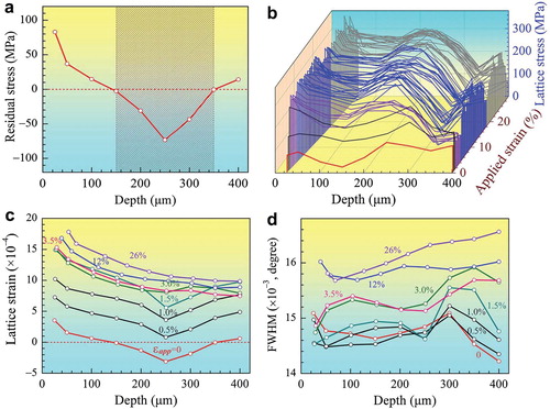
Figure (a) provides a clue to this puzzle. As shown, CRS existed in the depth range of 150–350 µm, which coincides with the layer of the strongest strain hardening. For simplicity, we refer to this layer as the CRS layer, while the adjacent layers with tensile residual stress (TRS) are referred to as the TRS layers. This observation indicates that CRS may be primarily responsible for the observed extraordinary broad strain-hardening peak, raises an issue: how does residual stress induces extra strain hardening?
During tensile testing, all layers are subjected to the same applied strain, which is superimposed on the residual elastic strain. With increasing applied strain, all layers in the sample first deform elastically. As shown in Figure (c), the CRS layer has a lower elastic strain than adjacent TRS layers on both sides up to the applied strain of ∼3.0%. This is because the applied tensile strain was first offset by the CRS in the CRS layer. This leads to a co-deformation stage in which the TRS layers are already deforming plastically, whereas the CRS layer still remains partially elastic. This produces two elastic–plastic interfaces demarcating the CRS and TRS layers. With increasing applied strain, the thickness of the elastic layer will shrink and the two elastic–plastic interfaces move toward each other and eventually meet at the depth where the highest compressive stress originally existed before tensile testing, after which the elastic layer disappears. This occurred at ∼3.0% of strain (Figure (c)).
The elastic–plastic interfaces result in a strain gradient near the interface in the plastic layer, which is accommodated by the geometrically necessary dislocations (GNDs) [Citation15,Citation23–25]. In other words, dislocations gliding in the adjacent plastically deforming layers may be blocked and pile-up near the two elastic–plastic interfaces. The pile-up of GNDs generates long-range back stress in the plastic layer [Citation15,Citation23–31]. The back stress needs to be balanced at the interfaces by forward-stress in the elastic layer, which contributes to the formation of the observed hardening belly, as shown in Figure (b). Together, the back stress and forward-stress produced HDI stress [Citation22]. Since the sample was SMAT-processed on both sides, there are two CRS layers and consequently four elastic–plastic interfaces to accumulate the GNDs. This makes the HDI hardening much more effective in the gradient structure than previously believed [Citation15].
Careful examination of the data for Figure (b) reveals that the strain hardening belly was formed at 1.5% applied strain, which was before the yield point. This indicates that strain hardening in the CRS layer was significant before yielding. In other words, the CRS directly contributed to enhancing yield strength. In addition, the TRS layers should also have contributed to the enhancement in yield strength by developing strong HDI hardening. Other contributing factors to yield strength include finer grains in the surface layer and high dislocation density produced by SMAT [Citation14–17]. This observation indicates that CRS contributed to the reported synergistic strengthening in gradient IF steel [Citation26].
In the above discussion, dislocation pileup near the elastic–plastic interface in the plastic layer contributed significantly to enhancing yield strength. This should logically increase the dislocation density in the plastic layers as they propagated into the CRS layer with increasing applied strain. This is verified by the evolution of the full width at half maximum (FWHM) of the synchrotron XRD peaks, which represents the evolution of dislocation density with increasing applied strain. As shown in Figure (d), the as-processed sample (0% strain) has the highest dislocation density at the depth of 300 μm. This is where the sample was plastically deformed by SMAT to produce dislocation cell and subgrains (Figure (e), (f)) [Citation14]. The dislocation density decreased from this peak point toward the surface because of grain refinement and dislocation recovery at very high plastic strains [Citation15]. The decrease in dislocation density toward the CG center is due to decreasing plastic strain.
With increasing applied strain, a dislocation density valley developed at 250 μm, which corresponds to the location of the highest CRS peak. This is consistent with an earlier discussion that the CRS layers remained elastic at the early deformation stage and therefore did not lead to the increase in dislocation density [Citation2]. Figure (d) shows that dislocation density quickly increased with increasing tensile strain on both sides at the depths of about 100 μm and above 300 μm. This indicates that dislocation pileups occurred on both sides of the CRS layers near the elastic–plastic interfaces [Citation27,Citation28].
Interestingly, a dislocation density peak appeared in the original CRS layer at 12% applied strain, which is long after the orginal CRS layer became plastic at ∼3.0% strain (see the blue curve in Figure (c)). This indicates that the original CRS layer left a legacy of higher dislocation hardening that lasted for large plastic strains, which is really helpful for preventing necking and maintaining high ductility. In other words, the CRS significantly contributed to maintaining ductility. As shown in Figure (a)–(c), high density of dislocations are accumulated at/near the grain boundaries at the initial stage of plastic deformation, which is markedly different from the conventional dislocation sub-structures in the interiors of grains and subgrains. Most of these dislocations are likely GNDs that were generated to accommodate strain gradient at elasto-plastic interfaces. These GNDs interacted and entangled with statistical dislocations, which helped with dislocation accumulation.
Figure 3. TEM observations of dislocation sub-structure evolutions. a and b, Increase in dislocation entanglement, especially at/near grain boundaries at ∼250 and 300 μm deep from top surface and at applied tensile strain of 3%. Also note dislocations in grain interior. c, Dislocations in grains at ∼250 μm deep from top surface and at applied strain of 15%.

CRS contributed to enhancing both the yield strength and ductility, as reflected in Figure . Compared with the CG sample, the GS sample has three times of yield strength and slightly higher ductility. This mechanical property is superior over those of other GS samples reported in the literature [Citation14–17].
Figure 4. Superior synergistic effect between yield strength and ductility in the GS sample. a, Engineering stress–strain curves of the GS and CG samples. The symbol § indicates uniform elongation. b, Strain hardening rate versus applied strain. Inset: Back stress versus strain.
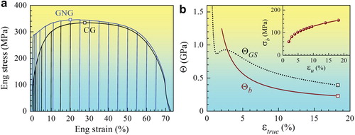
The initial stage of quick HDI hardening [Citation16,Citation26,Citation29] (inset in Figure (b)) coincides with the quick buildup of the dislocation density on both sides of the CRS layer at an early stage of tensile deformation (Figure (b)). HDI stress is induced by GND piling up [Citation27,Citation32], which indicates significant GND accumulation at the early stage of deformation. In addition, this process also coincides with the strain hardening uptick [Citation23] (see Figure (b)). As shown in Figure (b), the strain hardening uptick started at a strain of 1.5%, which corresponds to the establishment of the strain hardening belly. In other words, the strain hardening in the CRS layer is directly related to the starting of the strain hardening uptick. Figure (b) also reveals that the strain hardening uptick ended at a strain of ∼3%, which is the point the whole CRS layer started plastic deformation. These observations suggest that strain hardening uptick is associated with the direct forward-stress hardening in the shrinking elastic layer and the back-stress buildup in the plastic player as the plastic layers propagated into the two CRS layers.
The current observations represent a major breakthrough in our understanding of deformation physics and mechanical behavior of gradient materials. It is revealed that the CRS played a significant role in increasing the yield strength, and the HDI hardening as well as the dislocation forest hardening. The effect of CRS on the strength and ductility has never been reported before.
It should be noted that postmortem microhardness measurement is not adequate for studying the strain hardening behavior of gradient materials since it is not very sensitive to the effect of residual stress on the mechanical behavior. As shown in Figure (b), the microhardness did not show obvious deviation in the CRS layer and showed and monotonic smooth drop in the CRS layer. Lastly, the TRS layer on the surface observed here (Figure (a)) usually does not exist in conventional thick metal parts processed by shot peening. It is associated with thin plate samples processed by SMAT. We’d like to stress that the conclusion reached here is not affected by the existence of the TRS layer.
3. Conclusion
The gradient IF steel samples processed by SMAT have two CRS layers, which produced four dynamic elastic–plastic interfaces during tensile testing, where geometrically necessary dislocations are developed and accumulated to develop a strong back-stress hardening in the plastic layers. At the same time, forward-stress was produced in the elastic layer to result in higher tensile stress in it. This forward-stress was responsible for the establishment of the strain hardening belly in the CRS layer. The back and forward stresses produced the HDI hardening. These observations indicate that CRS played a major role in improving the strength and ductility, which provides some new ideas on the design of gradient materials.
Disclosure statement
No potential conflict of interest was reported by the authors.
ORCID
Run-Guang Li http://orcid.org/0000-0001-5395-0470
Additional information
Funding
Related Research Data
References
- Withers PJ. Bhadeshia HKDH. Residual stress. Part 2–nature and origins. Mater Sci Tech. 2001;17:366–375. doi: 10.1179/026708301101510087
- Lu J. editor. Handbook of measurement of residual stresses. New York: Fairmont Press; 1996.
- Webster GA. Role of residual stress in engineering applications. Mater Sci Forum. 2000;347–349:1–11. doi: 10.4028/www.scientific.net/MSF.347-349.1
- Fung YC. What are the residual stresses doing in our blood vessels? Ann Biomed Eng. 1991;19:237–249. doi: 10.1007/BF02584301
- Naaman AE. Prestressed concrete analysis and design: fundamentals (3rd ed.). Sarasota: Techno Press 3000; 2012.
- Ya M, Xing Y, Dai F, et al. Study of residual stress in surface nanostructured AISI 316L stainless steel using two mechanical methods. Surf Coat Tech. 2003;168:148–155. doi: 10.1016/S0257-8972(03)00254-8
- Roland T, Retraint D, Lu K, et al. Fatigue life improvement through surface nanostructuring of stainless steel by means of surface mechanical attrition treatment. Scr Mater. 2006;54:1949–1954. doi: 10.1016/j.scriptamat.2006.01.049
- Ortiz AL, Tian JW, Villegas JC, et al. Interrogation of the microstructure and residual stress of a nickel-base alloy subjected to surface severe plastic deformation. Acta Mater. 2008;56:413–426. doi: 10.1016/j.actamat.2007.10.003
- Zhang Y, Wang WH, Greer AL. Making metallic glasses plastic by control of residual stress. Nat Mater. 2006;5:857. doi: 10.1038/nmat1758
- Green DJ, Tandon RMSV, Sglavo VM. Crack arrest and multiple cracking in glass through the use of designed residual stress profiles. Science. 1999;283:1295–1297. doi: 10.1126/science.283.5406.1295
- Withers PJ. Residual stress and its role in failure. Rep Prog Phys. 2007;70:2211–2264. doi: 10.1088/0034-4885/70/12/R04
- James MN. Residual stress influences on structural reliability. Eng Fail Anal. 2011;18:1909–1920. doi: 10.1016/j.engfailanal.2011.06.005
- Chen AY, Li DF, Zhang JB, et al. Make nanostructured metal exceptionally tough by introducing non-localized fracture behaviors. Scr Mater. 2008;59:579–582. doi: 10.1016/j.scriptamat.2008.04.048
- Fang TH, Li WL, Tao NR, et al. Revealing extraordinary intrinsic tensile plasticity in gradient nano-grained copper. Science. 2011;331:1587. doi: 10.1126/science.1200177
- Wu XL, Jiang P, Chen L, et al. Extraordinary strain hardening by gradient structure. Proc Natl Acad Sci USA. 2014;111:7197–7201. doi: 10.1073/pnas.1324069111
- Kou H, Lu J, Li Y. High-strength and high-ductility nanostructured and amorphous metallic materials. Adv Mater. 2014;26:5518–5524. doi: 10.1002/adma.201401595
- Moon JH, Baek SM, Lee SG, et al. Effects of residual stress on the mechanical properties of copper processed using ultrasonic-nanocrystalline surface modification. Mater Res Lett. 2019;7:97–102. doi: 10.1080/21663831.2018.1560370
- Yuan FP, Yan DS, Sun JD, et al. Ductility by shear band delocalization in the nano-layer of gradient structure. Mater Res Lett. 2019;7:12–17. doi: 10.1080/21663831.2018.1546238
- Long J, Pan Q, Tao N, et al. Residual stress induced tension-compression asymmetry of gradient nanograined copper. Mater Res Lett. 2018;6:456–461. doi: 10.1080/21663831.2018.1478898
- Wang YD, Peng RL, Almer J, et al. Grain-to-grain stress interactions in an electrodeposited iron coating. Adv Mater. 2005;17:1221–1226. doi: 10.1002/adma.200401420
- Jia N, Cong ZH, Sun X, et al. An in situ high-energy X-ray diffraction study of micromechanical behavior of multiple phases in advanced high-strength steels. Acta Mater. 2009;57:3965–3977. doi: 10.1016/j.actamat.2009.05.002
- Zhu YT, Wu XL. Perspective on hetero-deformation induced (HDI) hardening and back stress. Mater Res Lett. 2019;7:393–398. doi: 10.1080/21663831.2019.1616331
- Wu XL, Jiang P, Chen L, et al. Synergetic strengthening by gradient structure. Mater Res Lett. 2014;2:185–191. doi: 10.1080/21663831.2014.935821
- Li J, Soh AK. Modeling of the plastic deformation of nanostructured materials with grain size gradient. Int J Plast. 2012;39:88–102. doi: 10.1016/j.ijplas.2012.06.004
- Zeng Z, Li XY, Xu DS, et al. Gradient plasticity in gradient nano-grained metals. Extr Mech Lett. 2016;8:213–219. doi: 10.1016/j.eml.2015.12.005
- Yang MX, Pan Y, Yuan FP, et al. Back stress strengthening and strain hardening in gradient structure. Mater Res Lett. 2016;4:145–151. doi: 10.1080/21663831.2016.1153004
- Wu XL, Zhu YT. Heterogeneous materials: a new class of materials with unprecedented mechanical properties. Mater Res Lett. 2017;5:527–532. doi: 10.1080/21663831.2017.1343208
- Ma E, Zhu T. Towards strength–ductility synergy through the design of heterogeneous nanostructures in metals. Mater Today. 2017;20:323–331. doi: 10.1016/j.mattod.2017.02.003
- Huang CX, Wang YF, Ma XL, et al. Interface affected zone for optimal strength and ductility in heterogeneous laminate. Mater Today. 2018;21:713–719. doi: 10.1016/j.mattod.2018.03.006
- Ashby MF. The deformation of plastically non-homogeneous materials. Phil Mag. 1970;21:399–424. doi: 10.1080/14786437008238426
- Liu XL, Yuan FP, Zhu YT, et al. Extraordinary Bauschinger effect in gradient structured copper. Scr Mater. 2018;150:57–60. doi: 10.1016/j.scriptamat.2018.03.007
- Wu XL, Yang MX, Yuan FP, et al. Heterogeneous lamella structure unites ultrafine-grain strength with coarse-grain ductility. Proc Natl Acad Sci USA. 2015;112:14501–14505. doi: 10.1073/pnas.1517193112