
 ?Mathematical formulae have been encoded as MathML and are displayed in this HTML version using MathJax in order to improve their display. Uncheck the box to turn MathJax off. This feature requires Javascript. Click on a formula to zoom.
Abstract
Researchers have always aimed to break the trade-off relationship between strength and ductility. In this study, a carbon diffusion strategy was provided to improve the strength and ductility of composite martensite steel simultaneously, as well as increase uniform ductility by 190%. The process strengthens the martensite without losing the hardening ability of austenite constituents and brings in a substantial transition layer. This strategy can also be applied to other composite alloys with light elements, thus providing a pathway for making high-strength and high-ductility materials.
GRAPHICAL ABSTRACT

IMPACT STATEMENT
An element diffusion strategy was provided, breaking the rule of averages and making composite martensite steel exhibit a higher strength and ductility than the monolithic martensite steel.
1. Introduction
Increasing the strength and ductility of materials has always been desirable [Citation1–4] not only for material researchers but for industry applications. However, a trade-off relationship between them is often activated, thus reducing the safety of structural parts. Martensite steel is an important structural material not only because of its high strength but also because of its simple heat treatment procedure. However, the ductility of martensite, especially its uniform ductility, is quite low under as-quenched-tempered conditions [Citation4,Citation5].
Many effects have been taken to deal with this weakness on martensite steel [Citation4–10]. Introducing soft constituents, such as ferrite [Citation6] and retained austenite [Citation7], into a martensite matrix, as well as combining soft austenite steel [Citation8–10], is a major method. On the basis of different pathways, such as multistep partitioning, including flashing [Citation4] and quench and partitioning [Citation7,Citation11], tailoring the retained austenite, especially its stability, to control transformation-induced plasticity processes, is attractive in the field of high-strength steel. Ductility can be increased, but tensile strength is usually reduced. Recently, some novelty methods, such as chemical boundary engineering [Citation12] and dislocation engineering [Citation1], have been developed to make high-strength and high-ductility steel.
Combining high-strength metals with high-ductility ones and producing multilayered structures with alternating hard and soft layers are other effective methods to improve the ductility of high-strength metals [Citation13–15]. The deformability of the hard layer can be increased under the coordination of the soft layer. Austenite steel with low strength and high ductility is an appropriate partner for martensite steel. Similarly, the strength of composite steel is reduced on the basis of the content of austenite steel and its strength difference with the base martensite steel, following the ‘rule of averages' [Citation16]. Previous studies normally limited element diffusion, such as that of carbon atom, between layers via short-time heat treatment after the bonding process [Citation10] or nickel layer insertion [Citation8] to avoid the deterioration of the mechanical properties of high-strength and high-ductility layers [Citation16]. This results in a nearly unchanged fundamental microstructure on the martensite layer, except for a refined grain size, which cannot fully compensate the strength loss due to the soft austenite. Thus, whether we can introduce an extra strengthening path to balance strength loss without deteriorating improved ductility must be explored.
In the present study, a new element diffusion strategy, namely, long-range diffusion of light elements, such as carbon, is provided. This strategy does not degrade the mechanical properties of each layer and increases the strength and ductility of the composite martensite steel compared with the initial monolithic martensite steel.
2. Materials and methods
The nominal chemical composition of the martensite steel sheet is 0.22 C–1.44 Si–1.20 Mn–1.52 Cr–0.36 Mo (in wt%), and the austenite steel is chosen as traditional Hadfield steel, with a simple composition of 1.0 C–13.2 Mn–0.18 Si (in wt%). The thickness ratio of the martensite and Hadfield sheets is 2:1, with an initial thickness of 1.6 and 0.8 mm, respectively. After all sheet surfaces were smoothed and cleaned, five martensite sheets and four Hadfield sheets were stacked into laminates in an alternating sequence, and then the laminates were placed in a steel box (material: Q235 steel). The box was welded using inert gas shielded arc welding. Then, the box was heated to 1150°C and held for 30 min, followed by three passes of hot rolling process, with a total reduction of 85%. The rolled box was further held at 1150°C for 5 min for element diffusion, and then it was water quenched to room temperature, followed by tempering treatment at 200°C for 1 h. Moreover, the reference monolithic martensite steel and Hadfield steel were hot rolled and tempered using the same procedure as the above box.
The outside box was removed before microstructure characterization and tensile tests. Microstructures were examined by optical microscopy (Axiover 200MAT) and transmission electron microscopy (TEM, FEI-Talos F200S), and the concentrations of alloying elements in each layer were detected via electron microprobe analysis (EMPA, JXA-8530F). An X-ray diffraction (XRD, SmartLab) profile was recorded using a Rigaku 9 kW with Co Kα radiation. All the profiles were obtained by varying 2θ from 40° to 120°, with a step scan of 0.02°. The time spent for collecting data per step was 4 s. The diffraction profiles were corrected for instrumental broadening by using a silicon sample, which had large crystallites and was free from the defects. The Williamson–Hall method was used to estimate the dislocation density and the classical ‘sin2ψ’ method was applied to evaluate internal stress by using ψ = 0°, 15°, 30°, and 45° for 110 reflection. Tensile tests were conducted at room temperature using a SHIMADZU AG-IS machine at a strain rate of 1 × 10⁻³ s−1, and the gauge size of the specimen was 10 mm × 3 mm × 1.5 mm (L × W × H), cutting along the rolling direction. Vickers hardness measurements were performed on a Quness 10A+ microhardness tester, and a load of 100 g was applied for 10 s at each location.
3. Results and discussions
The stacking structure in the box is shown in Figure (a), with the outside set as the martensite layer. The initial microstructures of the martensite and Hadfield steel were typical lath martensite and full austenite, respectively, as shown in Figure (b) and 1(c). After the hot working process, the layers were fully connected, and no microvoid and crack appeared at interfaces, as shown in Figure (d). The final thickness of the martensite and Hadfield layers was 260 ± 18 and 135 ± 12 μm, respectively, which are similar to the initial thickness ratio. At a high temperature of 1150°C, the two constituents were all in austenite state, and the strength difference between them was small, allowing the synchronous deformation of each layer. Interestingly, a substantial amount of twin martensite occurred in the martensite layer, especially near the interface (Figure (e) and 1(f)), indicating the increased carbon content in this layer. No considerable difference was observed in the center of Hadfield layer (Figure (g)), but dislocations and deformation twins had high density at the interface region of this layer (Figure (f)).
Figure 1. Stacking structure in the box (a), microstructures of monolithic steel (b and c) and composite steel (d–g). Martensite steel (b) and Hadfield steel (c), optical observation on composite steel (d), and TEM microstructure of the martensite layer (e), interface region (f), and Hadfield layer in accordance with the square regions marked A, B, and C in d.
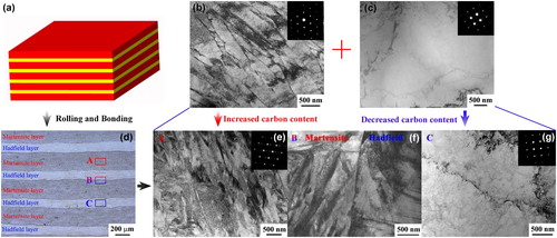
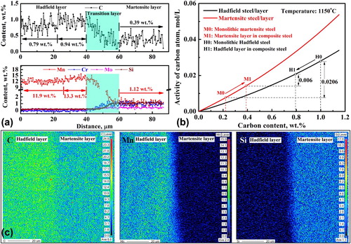
Figure shows the distribution of alloying elements between the neighbor layers tested via EMPA. The content gradient of all alloying elements, even carbon, could be observed, and a transition layer (approximately 20 μm thick) exited between the neighbor layers (Figure (a)), indicating that the alloying elements were diffused. The carbon content in the center of the Hadfield layer was reduced from 1.0 wt% to 0.79 wt%, resulting in the increased carbon content from 0.22 wt% to 0.39 wt% in the center of the neighboring martensite layer (Figure (a)). The activity of carbon atoms was estimated using Thermal Calc software, which revealed that the activity difference of carbon at 1150°C was 0.0206 mol/L before diffusion and was reduced to 0.006 mol/L afterward (Figure (b)). The activity of carbon atoms was estimated by using the mean carbon content and the content of other alloying elements in the center of each layer. The reduced activity difference decreased the driving force of carbon diffusion. Moreover, the diffusion of heavy elements, such as Mn, just occurred in the transition layer, without Mn increments in the center of the martensite layer (Figure (a)). This result is due to the slower diffusion rate of heavy elements with a large atomic radius, as compared with carbon atoms, and the fast-rolling process and short holding time afterward. Certain content of Si element is important for the carbon diffusion process, which increases carbon activity in austenite [Citation17] and reduces activity difference, thereby slowing down the diffusion process. Undoubtedly, the added short holding time of 5 min after the hot rolling process is another crucial factor for the element diffusion process. Moreover, the carbon content in the Hadfield layer and near the interface was higher than the interior. The interface seemed to have acted as a barrier impeding the diffusion process, even for light elements, such as carbon, although metallurgical bonding was realized after the hot rolling–bonding process, as shown in Figure (f).
Figure 2. EMPA results on the content of alloying elements between neighbor layers (a and c) and calculated carbon activity using Thermal Calc software (b).
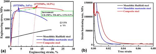
The resulting mechanical properties from this new process and its comparison with the reference monolithic steel are shown in Figure (a). Not only did uniform ductility and total ductility increased by 190% and 40%, respectively; the yield strength and ultimate tensile strength considerably increased in comparison with the monolithic martensite steel treated by the same hot working process. The higher strain-hardening rate of composite steel, as shown in Figure (b), should be responsible for the increased mechanical properties. The strength and elongation of this composite steel were also higher than the one without a final 5 min holing process after hot rolling for element diffusion (Figure S1). This result directly demonstrates that introducing the carbon diffusion strategy can simultaneously improve the strength and ductility of high-strength composite steel. Furthermore, the high-ductility feature of the Hadfield steel and its coordinating effect on martensite steel was not deteriorated, albeit providing some carbon atoms to martensite. The carbon atoms are crucial to the hardening ability of austenite [Citation18]. Moreover, the reducing rate of flow stress after necking was much slower than the monolithic martensite, indicating a higher safety feature of this composite steel.
Figure 3. Engineering stress–strain curves (a) and the corresponding strain-hardening rate–strain curves (b) of composite steel and the reference monolithic steel. Note: UD, TD, UTS, and YS indicate uniform ductility, total ductility, ultimate tensile strength, and yield strength, respectively.
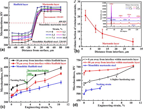
The long-range diffusion of carbon atoms into martensite inevitably increases its strength and creates a thick transition layer in combination with the diffusion of other elements, such as manganese, directly resulting in a gradually increased hardness from the interior of the Hadfield layer (235 HV) to the martensite layer (649 HV), as shown in Figure (a). Although some carbon and manganese atoms were lost, the hardness of the Hadfield layer was higher than the reference monolithic Hadfield steel (228 HV), with a slight increase in the interior and a higher increase near the interface (black line in Figure (a)). After the hot working process, the transformation strain due to martensite transformation in the martensite layer directly caused a slightly compressive deformation on the adjacent Hadfield layer. Therefore, the dislocation density at the interface region and interior of the Hadfield layer, estimated via XRD results, was approximately 5.07 × 10¹⁴ and 2.28 × 10¹⁴ m−2, respectively, which are higher than that in the reference Hadfield steel (approximately 1.61 × 10¹⁴ m−2). This should be responsible for the increased hardness in Hadfield layer. The dislocations can trap the carbon atoms effectively [Citation19]. Therefore, more carbon atoms were trapped at the interface of the Hadfield layer during the diffusion process, resulting in a higher carbon content at the interface region, as shown in Figure (a). Moreover, relatively higher carbon and manganese contents (Figure (a)) and relatively larger deformation degrees were observed near the interface (Figure (f)), further improving the hardness at the interface region of the Hadfield layer. For the martensite layer, the higher contents of austenite stabilized elements, such as carbon and manganese, near the interface (Figure (a)), resulting in more retained austenite after martensite transformation (Figure (b)), in turn bringing in a lower hardness in this region compared with that in the interior.
Figure 4. Hardness evolution in composite steel and its comparison with monolithic steel (a, c, and d) and the volume fraction of retained austenite in the martensite layer (b).
According to the modified mixture law [Citation20], to increase the strength of composite steel, the strength increment in martensite layer should be larger than the strength decrement due to the introduction of a soft Hadfield layer, that is,
(1)
(1) where VM and VH are the volume fraction of the martensite and Hadfield layers, respectively; HM and HH ′ are the hardness of the monolithic martensite steel and the Hadfield layer, respectively; ΔHM is the hardness difference between the martensite layer and the monolithic martensite steel. In accordance with the interior hardness and mean thickness of each layer, the hardness increment in the left of Formula (1) was estimated to be 106 HV, and the hardness decrement in the right was approximately 77 HV, satisfying Formula (1). This factor is the reason for the increased strength of the composite steel compared with the monolithic martensite steel.
A high-ductility soft layer is a key factor to guarantee the deformability of the matrix in composite metals. The Hadfield steel is a classical high-ductility alloy due to its high strain-hardening ability [Citation21,Citation22]. Previous studies have demonstrated that decreasing carbon content in high manganese steel reduced dynamic interactions between carbon atoms and dislocations, thus reducing its strain-hardening ability and ductility [Citation20,Citation23]. The effect of reduced manganese content on the Hadfield layer was weak due to a small reduction in content and slight effect on stacking fault energy when manganese content was within this range [Citation24]. However, the hardness evolution with increasing strain (Figure (c)) revealed the higher strain-hardening behavior of the Hadfield layer compared with the reference steel, especially when the strain exceeded the turning point of 3.3%. This guarantees the coordination ability of the Hadfield layer on the adjacent martensite layer, resulting in a persistent deforming behavior, as shown in Figure (d). A higher hardening rate in the interface region than that in the interior of martensite layer is attributed to the higher fraction of retained austenite (Figure (b)).
In conclusion, the high strain-hardening ability of the Hadfield layer is reserved even though it contributed 20% carbon to martensite. This point is strategic for the success of the element diffusion strategy in this study. First, the initial hardening rate of the Hadfield layer is comparable to that of the monolithic steel. According to the element distribution results (Figure (a)), a transition layer (approximately 20 μm thick) existed between two layers, and its thickness increased to approximately 45 μm in accordance with the hardness distribution (Figure (a)). This result indicates that the composite steel is composed of Hadfield, martensite, and gradient layers. Several interesting studies on gradient structure have revealed that the stress incompatibility yielded at the interface between fine and coarse grains could cause a strain gradient, which would be accommodated by geometrically necessary dislocations (GNDs) in the gradient region [10,13, Citation25–27]. The pileup of GNDs yielded back stress, which considerably enhanced strain hardening and increased the ductility of the gradient structure [Citation25–27]. This phenomenon occurs not only in gradient materials but also in lamellar composite structures [Citation10,Citation13] and nonhomogeneous materials [Citation28,Citation29]. The large strength difference between the martensite and Hadfield layers inevitably yielded heterogeneous deformation and therefore induced a strain gradient at the interface to fit the different strains across the interface and force the two different kinds of layers to deform simultaneously during the deformation process. This heterogeneous deformation also contributed to the higher strain-hardening rate of composite steel, especially to the up-turn hardening during the early deforming stage (Figure (b)), due to back stress hardening [Citation25]. Moreover, a strain gradient was also formed in the Hadfield layer during the cooling process due to the martensite transformation in the adjacent layer. Therefore, the high strain-hardening ability of the Hadfield layer was reserved due to the extra back stress hardening from the heterogeneous deformation of neighbor layers, although some carbon and manganese atoms were lost.
Furthermore, the hardness evolution tendency is shown in Figure (c) reveals a simultaneously accelerated hardening rate in different regions of the Hadfield layer after the turning point, suggesting that other hardening mechanisms must be activated after 3.3% strain. The uniform ductility of the monolithic martensite steel in the present study was 3.6%. Moreover, increasing carbon content usually results in decreased uniform ductility. Therefore, the turning point in Figure (c) is in accordance with the theoretical necking strain of the produced martensite layer. Micronecking readily happened in the martensite layer after turning strain due to its natural feature characterized by the lateral shrinkage. This lateral instability was constrained and was stopped quickly by the adjacent Hadfield layer, similar to that observed on gradient Cu material [Citation30]. Lateral stress was forced on the Hadfield layer afterward, thus activating additional slip systems and facilitating the accumulation of dislocations (Figure S2). Therefore, an extra hardening effect occurred, and the hardening rate of the Hadfield layer was increased after the turning point.
4. Conclusions
In summary, an element diffusion strategy was proposed and demonstrated to be effective on breaking the trade-off relationship between the strength and ductility of martensite composite steel, with strength and ductility improved by 9.5% and 40%, respectively. A multilayered structure with a gradient transition layer distributed between the neighbor layers was fabricated. The high strain-hardening rate of the Hadfield layer was reserved, even though some carbon atoms, which are critical for excellent mechanical properties, were lost. The proposed strategy is a general conception, and other light elements, such as nitrogen, can also be selected.
Supplemental Material
Download MS Word (1.4 MB)Acknowledgments
This project was funded by the National Natural Science Foundation of China (Grant Nos. 51871192 and 51831008), and the Natural Science Foundation of Hebei Province of China (E2020203058).
Disclosure statement
No potential conflict of interest was reported by the author(s).
Additional information
Funding
References
- He BB, Hu B, Yen HW, et al. High dislocation density-induced large ductility in deformed and partitioned steels. Science. 2017;357:1092–1032.
- Gao JH, Jiang SH, Zhang HR, et al. Facile route to bulk ultrafine-grain steels for high strength and ductility. Nature. 2021;590:262–267.
- Sun WW, Wu YX, Yang SC, et al. Advanced high strength steel (AHSS) development through chemical patterning of austenite. Scr Mater. 2018;146:60–63.
- Liu SL, Hu B, Li W, et al. Refined heterogeneous phase unit enhances ductility in quenched ultra-high strength steels. Scr Mater. 2021;194:113636.
- Nambu S, Michiuchi M, Ishimoto Y, et al. Transition in deformation behavior of martensitic steel during large deformation under uniaxial tensile loading. Scr Mater. 2009;60(4):221–224.
- Movahed P, Kolahgar S, Marashi SPH, et al. The effect of intercritical heat treatment temperature on the tensile properties and work hardening behavior of ferrite–martensite dual phase steel sheets. Mater Sci Eng A. 2009;518(1):1–6.
- De Moor E, Lacroix S, Clarke AJ, et al. Effect of retained austenite stabilized via quench and partitioning on the strain hardening of martensitic steels. Metall Mater Trans A. 2008;39(11):2586–2595.
- Ojima M, Inoue J, Nambu S, et al. Stress partitioning behavior of multilayered steels during tensile deformation measured by in situ neutron diffraction. Scr Mater. 2012;66(3–4):139–142.
- Bouaziz O, Masse JP, Petitgand G, et al. A novel strong and ductile TWIP/martensite steel composite. Adv Eng Mater. 2016;18(1):56–59.
- Kim JG, Baek SM, Lee HH, et al. Suppressed deformation instability in the twinning-induced plasticity steel-cored three-layer steel sheet. Acta Mater. 2018;147:304–312.
- Gao GH, Zhang H, Gui XL, et al. Enhanced ductility and toughness in an ultrahigh-strength Mn–Si–Cr–C steel: the great potential of ultrafine filmy retained austenite. Acta Mater. 2014;76:425–433.
- Ding R, Yao YJ, Sun BH, et al. Chemical boundary engineering: a new route toward lean, ultrastrong yet ductile steels. Sci Adv. 2020;6(13):eaay1430.
- Seok MY, Lee JA, Lee DH, et al. Decoupling the contributions of constituent layers to the strength and ductility of a multi-layered steel. Acta Mater. 2016;121:164–172.
- Lhuissier P, Inoue J, Koseki T. Strain field in a brittle/ductile multilayered steel composite. Scr Mater. 2011;64(10):970–973.
- Yu WX, Liu BX, He JN, et al. Microstructure characteristics, strengthening and toughening mechanism of rolled and aged multilayer TWIP/maraging steels. Mater Sci Eng A. 2019;767:138426.
- Koseki T, Inoue J, Nambu S. Development of multilayer steels for improved combinations of high strength and high ductility. Mater Trans. 2014;55(2):227–237.
- Kum DW, Oyama T, Ruano OA, et al. Development of ferrous laminated composites with unique microstructures by control of carbon diffusion. Metall Trans A. 1986;17(9):1517–1521.
- Bouaziz O, Zurob H, Chehab B, et al. Effect of chemical composition on work hardening of Fe—Mn—C TWIP steels. J Mater Sci Technol. 2011;27:707–709.
- Caballero FG, Miller MK, Garcia-Mateo C. Carbon supersaturation of ferrite in a nanocrystalline bainitic steel. Acta Mater. 2010;58:2338–2343.
- Fan Z, Tsakiropoulos P, Miodownik AP. A generalized law of mixtures. J Mater Sci. 1994;29(1):141–150.
- Liu FC, Yang ZN, Zheng CL, et al. Simultaneously improving the strength and ductility of coarse-grained hadfield steel with increasing strain rate. Scr Mater. 2012;66(7):431–434.
- Zhang FC, Chen C, Lv B, et al. Effect of pre-deformation mode on the microstructures and mechanical properties of hadfield steel. Mater Sci Eng A. 2019;743:251–258.
- Liu S, Qian LH, Meng JY, et al. On the more persistently-enhanced strain hardening in carbon-increased Fe–Mn–C twinning-induced plasticity steel. Mater Sci Eng A. 2015;639:425–430.
- Zambrano OA. Stacking fault energy maps of Fe–Mn–Al–C–Si steels: effect of temperature, grain size, and variations in compositions. J Eng Mater Technol. 2016;138(4):041010.
- Yang MX, Pan Y, Yuan FP, et al. Back stress strengthening and strain hardening in gradient structure. Mater Res Lett. 2016;4(3):145–151.
- Wu XL, Zhu YT, Lu K. Ductility and strain hardening in gradient and lamellar structured materials. Scr Mater. 2020;186:321–325.
- Cheng Z, Zhou HF, Lu QH, et al. Extra strengthening and work hardening in gradient nanotwinned metals. Science. 2018;362:eaau1925.
- Ashby MF. The deformation of plastically non-homogeneous materials. Philos Mag. 1970;21:399–424.
- Liu XL, Xue QQ, Wang W, et al. Back-stress-induced strengthening and strain hardening in dual-phase steel. Materialia. 2019;7:100376.
- Wu XL, Jiang P, Chen L, et al. Extraordinary strain hardening by gradient structure. Proc Natl Acad Sci USA. 2014;111:7197–7201.