
 ?Mathematical formulae have been encoded as MathML and are displayed in this HTML version using MathJax in order to improve their display. Uncheck the box to turn MathJax off. This feature requires Javascript. Click on a formula to zoom.
Abstract
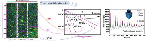
Hybrid manufacturing (HM) Ti-6Al-4V components combining the advantages of forging and additive manufacturing were achieved. The bonding zone of the HMed component joins the substrate and the additive manufactured zone and its α′-α/α′/αm-α/β heterogeneous microstructure was attributed to the distinguishing cooling rate and pseudo-isothermal annealing temperature. The phase transformation mechanisms were clarified with a numerical simulation model for thermal analysis. Moreover, preheating manipulate the size, volume fraction and distribution of α′/αm/α phases to tailor the heterogeneous microstructure.
GRAPHICAL ABSTRACT
IMPACT STATEMENT
Preheating can serve as an effective way to tailor the heterogeneous microstructure in the bonding zone of HMed Ti-6Al-4V by affecting the cooling rate and pseudo-isothermal annealing temperature.
1. Introduction
Ti-6Al-4V alloy is the most widely used metallic materials in the aeronautical and biomedical industries, which has received significant attention due to its high specific strength and admirable formability [Citation1,Citation2]. High-performance Ti-6Al-4V components are traditionally produced by thermo-mechanical treatment in multistage forging operations, which entail a low material yield. The additive manufacturing (AM) process is attractive, with an opportunity for near-net-shape manufacturing [Citation3]. However, the material cost and processing time in AM rise rapidly with the component size [Citation4]. In order to overcome the disadvantages of the above two different processing technologies, the hybrid manufacturing (HM) technology has been developed [Citation5–7]. The forging-additive HM manufactures the large and regular parts of a component through traditional forging and then manufactures the geometrically complex and small parts of the component through AM. This HM technology provides a much more resource-efficient alternative for manufacturing large and geometrically complex components [Citation8]. The wrought substrate is retained as a part of the final component in HM technology. This is different from the traditional AM process, where the substrate will be removed. Consequently, a metallurgical bonding zone (BZ) between the substrate and the AMed zone dramatically influences the mechanical performance of the whole component.
HMed parts often exhibited a strength mismatch among the substrate, AMed zone, and the bonding zone (BZ) [Citation9]. And their unsatisfying plasticity was caused by the complexity and variability of the microstructure in the BZ [Citation7]. How the heterogeneous microstructure forms in the BZ and whether it is able to be tailored have not been clarified. The numerical modeling has been used to unravel the formation mechanism of phases in the AMed zone by analyzing the thermal history [Citation8,Citation9]. Nevertheless, the thermal history-phase transformation-microstructure relationships were not established in the BZ. A numerical simulation model needs to be developed for its thermal analysis and practical guidance. A deeper understanding of the BZ is also desperately needed for other manufacturing applications such as laser welding and laser additive repaired technology [Citation10].
Tailoring the microstructure of the BZ is another essential scientific concern. Post heat treatments are generally applied to manipulate the size of α and α′ phases to improve the ductility of Ti-6Al-4V. In contrast, they inevitably change the original substrate and lead to the uncontrollability of improving the integral performance [Citation11]. Besides, the excessive pickup of oxygen and nitrogen at high post-heating temperatures would severely reduce the ductility. Low-temperature preheating treatment can be a helpful method to change the microstructure of the AMed components [Citation12]. Xu et al. [Citation13] preheated Ti-6Al-4V substrate (200 °C) to decompose the brittle and anisotropic α′ phase in the AMed zone. Vracken et al. [Citation14] found that preheating changed α′ to a more ductile mixture α+α′+β and improve the ductility of AMed Ti-6Al-4V. The effective preheating treatment has only been applied into tailoring the microstructure of the AMed zone. However, in previous works, the effect of preheating on microstructure and properties of the BZ has still not been mentioned.
In this work, the main goals are: (i) to investigate the heterogeneous microstructure of the BZ in HMed Ti-6Al-4V, (ii) to uncover the phase transformation mechanism of the BZ during the HM process, (iii) to demonstrate the effects of preheating on the microstructure of the BZ.
2. Experimental material and procedures
The forming process of the forging substrate is indicated in Fig S1(e). Preheating treatment was conducted in an electric stove on the LSF system platform. The HM process is shown in Fig S1(b,d) with its parameters shown in Table .
Table 1 An overview of the process parameters in HMed Ti-6Al-4V
The microstructure was characterized by optical microscope (OM) and TESCAN MIRAIII scanning electron microscopy (SEM) equipped with electron backscattered diffraction (EBSD) detector. The metallography methods for SEM/EBSD/TEM samples are shown in the Supplemental Material. X-ray diffraction analysis utilized CuKα radiation operated at 40 kV and 30 mA. Grain size analysis was through data analysis by Image J. Tensile testing samples along the building direction for the BZ with gauge dimensions of 12.5 mm × 3.0 mm × 2.0 mm were tested at a strain rate of 5 × 10⁻³ s−1. The temperature field simulation was conducted in the FE software package ABAQUS. The specific thermal properties are shown in Table S1.
3. Results and discussion
Figure presents the microstructures of HMed Ti-6Al-4V fabricated without preheating. Three zones along the building direction are identified in Figure (a): the laser deposited zone (LDZ) with columnar grains, the wrought substrate zone (WSZ) with duplex microstructure and the bonding zone (BZ) jointing them (∼1.0 mm).
Figure 1. (a) Optical microscope images of microstructures in HMed Ti-6Al-4V; (b-f) Microstructure evolution from the LDZ to the WSZ; (g) X-ray diffraction patterns (XRD) profile.
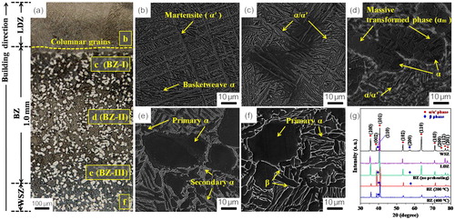
In the LDZ, the orthogonal α′ phase formed with little basketwave structure. Its XRD pattern (Figure (g)) confirmed the existence of α′ and α+β phase. The lattice parameters of α/α′ phase are close to α (a = 2.9406 Å, c = 4.6700 Å) and α′ (a = 2.9266 Å, c = 4.6677 Å), respectively (Fig S2). The top of the BZ (BZ-I) is also full of acicular α′/α phases in Figure (c). The α′ phase in this region becomes shorter than that in the LDZ. In the middle of the BZ (BZ-II) (Figure (d)), the transformed α phases (αm) and some smallish α′/α phases appear in former α phases which belong to the duplex microstructure. A mass of fine secondary α is prevalent among primary α on the bottom of the BZ (BZ-III) in Figure (e). The primary α phases are displayed as globular α and lamellar α in the WSZ (Figure (f)), where XRD shows evident α+β peaks. The BZ presents a heterogeneous microstructure with continuity, which can be attributed to the different thermal histories of these regions.
To clarify the thermal histories, the substrate and deposition materials are simulated in the FE model. The moving heat source was generated with DFLUX and the birth-dead-elements was generated. The thermal histories of three selected positions were shown in Figure (a). P1 is located in the surface of the BZ. P2 and P3 are located 0.4 mm and 1.0 mm under the P1, respectively. The thermal history of a point shows a series of peaks. Both the thermal peaks of P1 and P2 are far beyond the β-transus temperature. This implies that BZ-I and BZ-II have experienced multiple remelting involving α→β transformation and rapid solidification involving β→α transformation. The deposition processes are almost repeatable. So the final solidification process is regarded as the primary determinant.
Figure 2. (a) Thermal history of first 20 deposition layers without preheating at P1, P2, P3; (b) A diagram of Ti-6Al-4V CCT curve (adapted from Ref. [Citation15]) and corresponding schematic of the microstructure evolution.
![Figure 2. (a) Thermal history of first 20 deposition layers without preheating at P1, P2, P3; (b) A diagram of Ti-6Al-4V CCT curve (adapted from Ref. [Citation15]) and corresponding schematic of the microstructure evolution.](/cms/asset/c9a5f01b-d732-4cf3-9648-ba216173f1c5/tmrl_a_1958947_f0002_oc.jpg)
Taking P1 as an example, a high cooling rate (CR = 715.7 °C/s) was achieved during the last solidification stage (Figure (a)). From the continuous cooling transformation (CCT) curve (Figure (b)), martensitic transformation takes place when CR reaches beyond 410 °C/s. Thus, plentiful α′ phases occur in BZ-I (Figure (b)). Between P1 and P2, the transition region of the BZ experienced the solidification stage and solid-state phase transformation stage. After that, this region arrived at a heat preservation stage of ∼600 °C (decomposition temperature of α′), which could be set as a pseudo-isothermal annealing (PIA) stage in Figure (a) [Citation16]. α′ phases partially decomposed into α+β (Figure (c)). P2 has a moderate CR (∼202.5 °C/s) during the last solidification, where β→αm occurs between 20 °C/s and 410 °C/s (Figure (b)). With a lower CR, β→α′ transformation was gradually suppressed by β→αm transformation. The amounts of acicular α′/α phases decreased while αm phases increased from BZ-I to BZ-II. The highest peak temperature in P3 just reached the melting point of Ti-6Al-4V, suggesting the absence of rapid solidification in BZ-III. Here β phase would experience β→α with a low CR (29.4 °C/s). The secondary α tended to distribute among primary α (Figure (f)). On this account, a heterogeneous microstructure composed of α′-α/α′/αm-α/β was formed in the BZ.
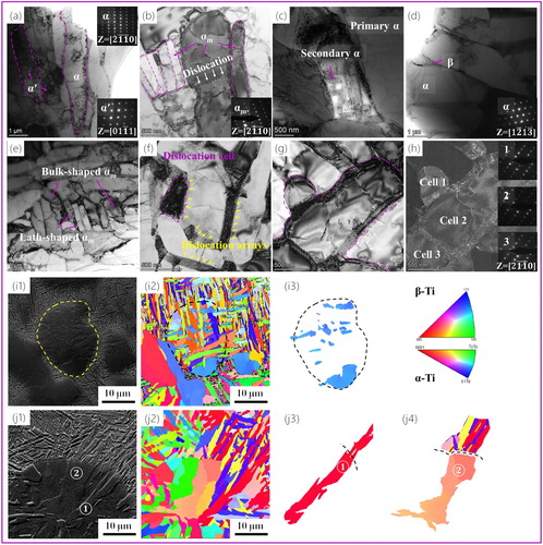
It should be noted that αm is particularly observed (Figure (d)), which has not yet been found in the BZ during HM Ti-6Al-4V [Citation17,Citation18]. To identify α/α′/αm in the BZ clearly, TEM observations (Fig S3(a)) display that α′ possesses a compressed version of a hcp lattice compared to α, which is obtained as a result of the diffusionless shear-type martensite transformation [Citation19]. The α′ martensite in Figure (a) and Fig S3(e) bears a high density of tangled dislocations that can effectively accommodate martensite transformation. α phase in the WSZ (Figure (d)) shows no dislocation. According to Figure (b,e) and Fig S3(f-g), the αm consists of bulk-shaped αm with minor dislocations and lath-shaped αm being about 200 nm wide stripes. Interestingly, the formation of dislocation arrays is observed (labeled with white arrows) in Figure (b). The ordered dislocation arrays form from the dislocation cell walls (Figure (f)), which is a typical static recovery process during the annealing treatment [Citation20]. Such a process is generally associated with the annihilation of the dislocation cell walls when deformation-induced dislocations rearrange themselves [Citation21]. And the dislocations arrays present a much stable configuration than the cells since they may greatly diminish the long range stress field [Citation22]. With a longer annealing time during the pseudo-isothermal annealing (PIA) stage, dislocation arrays in αm begin to appear. Figure (h) shows that the selected area diffraction patterns for the different regions in αm (surrounded by dislocations cells 1-3) have the same diffraction pattern as a symbol of nearly identical orientation. These connected dislocation arrays will transform into the low or high angle boundaries. The EBSD analysis was further performed on αm phases. Figure (i1-i3) shows the microstructure circled with the dotted line on behalf of transformed primary α. A part of primary α phase (marked in blue) was retained after β transformation and embodied the same crystal orientation in the pole figures (Figure (i3)). In Figure (j1), two typical types of αm phases are marked as and
. Figure (j3) shows this lath-shaped αm throughout the primary α, which transformed from β in the boundary since these αm phases show almost the same orientation angle. As shown in Fig S4(b), the orientation angle of αm
spreads about 4° in {0001} pole. More bulk-shaped αm phases (like αm
) grow inside the primary α (Figure (j4)), whose misorientation falls in a wide range from 5 to 25° [Citation17]. The orientation angle of αm
covers about 11° (Fig S4(c)) as well as the massive transformations in other alloys [Citation23]. And this misorientation can be identified as a low angle boundary, which is consistent with the transformation of the dislocation arrays in αm.
Figure 3. TEM images from BZ-I to the WSZ: (a) α′/α; (b) αm; (c) primary α and secondary α; (d) α and β; (e) bulk-shaped αm and lath-shaped αm; (f) Dislocations arrays (labeled with yellow arrows) and dislocations cells (circled with purple line) in αm; (g-h) Bright field image and dark field image of dislocations cells 1–3 in αm; (i1,j1) The α grains in BZ-II were extracted using Channel 5 software; (i2-i3) Inverse pole figure (IPF) color map of untransformed α (circled with dotted line); (j2-j4) IPF maps of transformed α ( and
).
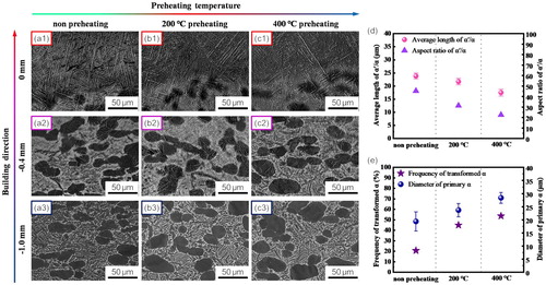
The heterogeneous microstructure is associated with the massive transformation and martensitic transformation, which is contributed to the thermal history. Therefore, preheating plays a crucial role in its formation. The pre-heated samples show similar phase compositions with the non-preheated (NP) sample (Figure (a-c). However, a distinct difference in size and the volume fraction of phases was caused by preheating. The average length of α/α′ phases decreases from 23.8 μm (NP) to 17.5 μm after 400 °C preheating (Figure (e)). Meanwhile the aspect ratio of the α/α′ phases reduces from 45.43 to 22.56. The α′ phases have a large aspect ratio resulting from high CR than α phases [Citation19]. With preheating, α gradually took over in α/α′ phases. So this descending change shows the less production or more decomposition of α′ (Figure (d)). Figure (e) indicates that the frequency of αm increases from 20.7% (NP) to 53.7% (400 °C preheating) in BZ-II. This inconsistency is due to partial αm in place of α′ after preheating. The Ms temperature of martensitic transformation is accepted to be 800 °C, and that of massive transformation will rise along with the lower CR. The starting temperature of β→αm is higher than the martensitic one. With preheating, a massive transformation is more likely to happen. Moreover, Figure (e) suggests that preheating causes a coarsening of primary α phases from about 19.3 μm to 28.4 μm wide in BZ-III. There are almost no changes in the WSZ before and after preheating (Fig S5(a-b)), which further indicates that low-temperature preheating can tailor the microstructure of the BZ and preserve the microstructure of other zones.
Figure 4. (a-c) SEM micrographs of HMed Ti-6Al-4V: (a1-a3) Without preheating; (b1-b3) 200 °C; (c1-c3) 400 °C; (d) Preheating resulting average length and aspect ratio of α/α′; (e) Influence of preheating on the frequency of αm and the diameter of globular α.
The preheating treatment also resulted in the change of phase distribution at mesoscale in Figure (a-c). The width of the BZ decreases from 1,000 μm to 350 μm with 400 °C preheating. During the heating stage, the zone affected by heat source expands shown in Figure (d). Although the heat affected zone was enlarged by preheating, the region of the BZ where phase transformation happens distinctly became narrower.
Figure 5. (a-c) EBSD Euler maps of the BZ: (a) Without preheating; (b) 200 °C; (c) 400 °C; (d) The simulated results at the beginning of deposition; (e) Thermal history of first 20 deposition layers in 0 mm; (f) Dependent cooling rates during the cooling process and the mean annealing temperature (Tmean) during the PIA process.
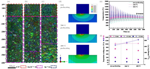
Owing to heat dissipation, the mean PIA temperature in P1 (NP) is about 698.5 °C, which is similar with that after preheating. While preheating elevates the PIA temperature in P2 by ∼170 °C (Figure (f)) and promotes the formation of secondary α (Figure (c)). In Fig S5(f), NP tensile samples for the BZ have a yield tensile strength (YTS∼892 MPa) and ultimate tensile strength (UTS∼941 MPa) with 9.0% elongation (EL). YTS, UTS and EL of the 400 °C-preheating samples are 937, 989 MPa and 8.4%, respectively. Their higher YTS and UTS compared to the NP samples and annealing (850 °C/2 h) samples may be attributed to the strengthening effect of the generated secondary α phases [Citation24]. As mentioned in heterostructured materials, a good combination of strength and ductility of the BZ samples can also be achieved by controlling the volume fraction of martensite and morphology of each phase [Citation25]. All in all, the pre-heat treatment can be a convenient approach to tailoring the heterogeneous microstructure in the BZ.
4. Conclusion
HMed Ti-6Al-4V components are achieved on forging substrate and the microstructure and phase transformation of the BZ at different preheating temperatures were investigated. The main finding can be summarized below:
A numerical simulation model is developed for thermal analysis of the BZ. Solidification and solid-state phase transformation of Ti-6Al-4V are associated with respective thermal history during HM process, leading to a heterogeneous microstructure consisting of α′, αm, α and β phases from BZ-I to BZ-III. α′ bears a high density of tangled dislocations that can effectively accommodate martensite transformation. αm consists of dislocation arrays, which form from the dislocation cell walls and can transform into low angle boundaries during the pseudo-isothermal annealing (PIA) stage.
The high cooling rate (
410 °C/s) triggers martensite transformation in BZ-I. Martensite transformation is superseded by massive transformation in BZ-II because of the decreasing cooling rate. The width of the BZ decreases with the enhancing temperature at a mesoscale. The established cooling rate-phase transformation-microstructure relationships provide us even more convenient approach to tailor the heterogeneous microstructure.
Preheating can decrease the cooling rate to manipulate the size, volume fraction and distribution of α′/αm phases. In addition, preheating can increase the PIA temperature to generate secondary α phases. These changes of the heterogeneous microstructure improve the strength of HMed Ti-6Al-4V.
Supplemental Material
Download MS Word (7.2 MB)Disclosure statement
No potential conflict of interest was reported by the author(s).
Additional information
Funding
References
- Peters M, Hemptenmacher J, Kumpfert J, et al. Structure and properties of titanium and titanium alloys. Titanium and Titanium Alloys. 2005;1:1–36.
- Banerjee D, Williams JC. Perspectives on titanium science and technology. Acta Mater. 2013;61(3):844–879.
- Gisario A, Kazarian M, Martina F, et al. Metal additive manufacturing in the commercial aviation industry: A review. J. Manuf. Syst. 2019;53:124–149.
- Froes FH, Dutta B. The additive manufacturing (AM) of titanium alloys. Adv Mater Res. 2014;1019:19–25.
- Huang CJ, Yan XC, Chen CY, et al. Additive manufacturing hybrid Ni/Ti-6Al-4V structural component via selective laser melting and cold spraying. Vacuum. 2018;151:275–282.
- Hernández-Nava E, Mahoney P, Smith CJ, et al. Additive manufacturing titanium components with isotropic or graded properties by hybrid electron beam melting/hot isostatic pressing powder processing. Sci Rep. 2019;9:4070.
- Dharmendra C, Shakerin S, Ram GDJ, et al. Wire-arc additive manufacturing of nickel aluminum bronze/stainless steel hybrid parts – interfacial characterization, prospects, and problems. Materialia. 2020;13:100834.
- Bermingham MJ, StJohn DH, Krynen J, et al. Promoting the columnar to equiaxed transition and grain refinement of titanium alloys during additive manufacturing. Acta Mater. 2019;168:261–274.
- Shrestha S, Panakarajupally RP, Kannan M, et al. Analysis of microstructure and mechanical properties of additive repaired Ti–6Al–4V by direct energy deposition. Mater Sci Eng A. 2021;806:140604.
- Shim DS, Lee H, Son Y, et al. Effects of Pre- and post-repair heat treatments on microstructure and tensile behaviors of 630 stainless steel repaired by metal additive manufacturing. J Mater Res Technol [Internet. 2021;13:980–999.
- Shipley H, McDonnell D, Culleton M, et al. Optimisation of process parameters to address fundamental challenges during selective laser melting of Ti-6Al-4V: A review. Int J Mach Tools Manuf. 2018;128:1–20.
- Meng W, Xiaohui Y, Zhang W, et al. Additive manufacturing of a functionally graded material from Inconel625 to Ti6Al4V by laser synchronous preheating. J Mater Process Technol. 2020;275:116368.
- Xu W, Lui EW, Pateras A, et al. In situ tailoring microstructure in additively manufactured Ti-6Al-4V for superior mechanical performance. Acta Mater. 2017;125:390–400.
- Vrancken B, Buls S, Kruth J-P, et al. Influence of preheating and oxygen content on Selective Laser Melting of Ti6Al4V. Proc 16th RAPDASA Conf. 2015.
- Yang T, Xu D, Chen W, et al. Microstructure evolution and deformation resistance of heavy-thickness Ti-6Al-4V narrow-gap welded joints. Mater Lett. 2019;250:116–118.
- Zafari A, Barati MR, Xia K. Controlling martensitic decomposition during selective laser melting to achieve best ductility in high strength Ti-6Al-4V. Mater Sci Eng A. 2019;744:445–455.
- Lu SL, Qian M, Tang HP, et al. Massive transformation in Ti-6Al-4V additively manufactured by selective electron beam melting. Acta Mater. 2016;104:303–311.
- Massalski TB. Massive Transformations Revisited. 2002;33:2277–2283.
- Yang J, Yu H, Yin J, et al. Formation and control of martensite in Ti-6Al-4V alloy produced by selective laser melting. Mater Des. 2016;108:308–318.
- Wang B, Tang B, You C, et al. Dislocation arrays, precipitate bands and free zones in forged Mg-Gd-Y-Zr alloy. Mater Sci Eng A. 2020;775:138789.
- Hong C, Huang X, Winther G. Dislocation content of geometrically necessary boundaries aligned with slip planes in rolled aluminium. Philos Mag. 2013;93:3118–3141.
- You C, Liu C, Wan Y, et al. Dislocations-induced precipitates and their effect on mechanical properties of Mg-Gd-Y-Zr alloy. J Magnes Alloy Internet. 2019;7:414–418.
- Plichta MR, Williams JC, Aaronson HI. On the existence of the β→αm transformation in the alloy systems Ti-Ag, Ti-Au, and Ti-Si. Metall Trans A. 1977;8(12):1885–1892.
- Ma J, Zhang Y, Li J, et al. Microstructure and mechanical properties of forging-additive hybrid manufactured Ti–6Al–4V alloys. Mater Sci Eng A. 2021;811:140984.
- Zhu Y, Ameyama K, Anderson PM, et al. Heterostructured materials: superior properties from hetero-zone interaction. Mater Res Lett Internet. 2021;9:1–31.