
 ?Mathematical formulae have been encoded as MathML and are displayed in this HTML version using MathJax in order to improve their display. Uncheck the box to turn MathJax off. This feature requires Javascript. Click on a formula to zoom.
Abstract
Titania nanotube arrays are an exceptionally adaptable material for various applications ranging from energy conversion to biomedicine. Besides electronic properties, structural morphology on nanometre scale is essential. It is demonstrated that ion implantation constitutes a versatile method for the synthesis of tailored nanotube morphologies. Experimental-phenomenological observations reveal a successive closing behaviour of nanotubes upon ion implantation. Employing molecular dynamics calculations in combination with analytical continuum models, the physical origins of this scenario are unravelled by identifying ion bombardment induced viscous flow driven by capillarity as its underlying mechanism besides minor contributions from sputtering and redeposition. These findings enable the tailoring of nanotube arrays suitable for manifold applications.
GRAPHICAL ABSTRACT
IMPACT STATEMENT
This work presents a unified framework for understanding and predicting ion-induced effects in nanotube structures by a combination of experiments, modelling and analytical theory.
Introduction
Titania (TiO2) nanotubes have attracted tremendous interest during the past decade as they combine the versatility of TiO2 with an exceptionally ordered nanoscale geometry and an enormous surface to volume ratio for novel applications in a broad range of areas [Citation1]. Synthesis is usually realized by self-organized structure formation during electrochemical anodization, such that detailed ‘recipes' for the desired properties are formulated [Citation2,Citation3]. Besides fingerprints on morphologies, synthesis parameters also leave their mark on the molecular structure, both of which severely affect materials functionality due to modified chemical or physical characteristics (e.g. surface free energy or electronic structure) [Citation4]. Exploiting specifically optimized features, superior properties become feasible, especially unprecedented biocompatibility, protein adsorption, cell adhesion or bioactivity in tissue culturing [Citation5–8]. Furthermore, the photocatalytic activity and photocurrent density of nanotube arrays can be regulated [Citation9–11]. While doping with electronic defect states [Citation12–14] constitutes one way of modifying electronic structure after synthesis, methods to morphologically modify synthesized nanotube arrays either on a global or local scale are not established at this point. As we will demonstrate in the following, ion beam bombardment constitutes an attractive tool not only for doping, but also for morphological optimization—globally (using a homogeneous ion beam, as shown by us in the following) as well as spatially resolved (when applying masks or focused ion beams). As our modeling approach indicates, morphological shaping within the presently applied implantation energy regime is largely goverend by relaxation of introduced point defects; we thus expect comparable physics for different ion species, energies and fluences when normalized to point defect production yield. Hence, we concentrate on carbon implantation to retain the excellent biocompatibility of the amorphous TiO2 nanotube arrays.
Previous work on the application of ion beams primarily focused on the impact of dopants on electronic properties, while morphology optimization had not been in the focus. For instance, Ghicov et al. demonstrated [Citation15], that annealing and nitrogen implantation of TiO2 nanotubes yielded higher photocurrents. However, they observed that implanting nitrogen into amorphous TiO2 nanotubes would cause unfavourable changes in the surface topography [Citation16]. They obtained ‘sponge-like’ morphologies that were explained as an irradiation-induced destruction of the structure due to introduced defects and vacancies. Contrasting these results, Zhou et al. in 2016 did not report about morphological changes of nitrogen implanted amorphous TiO2 nanotubes [Citation12]. Recently, a systematic approach to determine the effects of nitrogen ion bombardment of magnetron sputtered TiO2 thin films was given by Panepinto et al. [Citation17]. However, a concise picture of the material effects on a sub-nanometre-scale was not drawn.
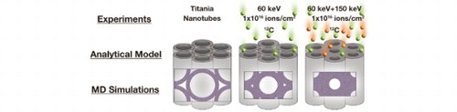
In the following, we first report about our experimental finding on the impact of energetic ion bombardment on nanotube morphology that is characterized by a successive shrinking of tube radius. Employing large-scale molecular dynamics (MD) simulations and analytical continuum models, we subsequently unravel the physics behind these experimental observations and highlight the prominent role of capillarity-driven radiation-induced viscous flow in pattern shaping during ion beam postprocessing.
Materials and methods
TiO2 nanotube array fabrication
TiO2 nanotube arrays in two different shapes were prepared at room temperature using electrochemical anodization, as detailed in Supplemental Material. Free standing nanotube (NT) arrays are comprised of single nanotubes and synthesized in one step, while nanoporous (NP) arrays with connected tube walls and a pore-like morphology require two subsequent anodizations.
Scanning electron microscopy
Using scanning electron microscopy (SEM, Quanta FEG 200, FEI company, 10 keV acceleration voltage and 5–6 mm working distance, Everhart–Thornley secondary electron detector), we analyzed the dimensions of the NT and NP topography, as well as the structural homogeneity on large areas. The average outer diameters ± standard deviation of NT and NP were obtained from SEM images with Fiji software [Citation18] with at least 25 measurements per sample.
Ion implantation
Implantation of mass separated 12C ions was realized using an IMC-200 ion implanter (Ion Beam Services, France) with acceleration voltages of 60 keV or 150 keV. The samples were implanted at a standard tilt angle of 7° to prevent channeling effects. Energy deposition during implantation was small enough to restrict substrate heating to ca. 50°C or less. Either a fluence of 1 × 10¹⁶ ions/cm2 at 60 keV was applied, or a combination of both acceleration voltages (60 and 150 keV) with a fluence of 1 × 10¹⁶ ions/cm2 each was chosen.
Molecular dynamics (MD) computer simulations
We numerically solve the classical multiparticle problem for TiO2 by integrating the equations of motions for the Matsui and Akaogi empirical potential [Citation19], truncated beyond a cutoff of 9 Å with a method due to Wolf et al. [Citation20], using a 5th order Gear predictor–corrector scheme [Citation21] (1.63 fsec time step) as implemented in our group maintained code [Citation22]. Details are given in Supplemental Material.
Results and discussion
Experimental phenomenology
Two different types of regular amorphous TiO2 nanostructures, viz. free-standing nanotube (NT) and nanopore (NP) arrays were synthesized by self-organization during anodization, as detailed in the Materials and Methods section. Representative scanning electron microscopy (SEM) topographs of the as prepared samples are shown in Figure . 12C doping is subsequently realized by ion implantation using energies either of 60 keV or a combination of 60 keV and 150 keV.
Figure 1. SEM measurements of NT and NP arrays before and after implantation. The diameters of both NT and NP decrease with increasing carbon fluence.
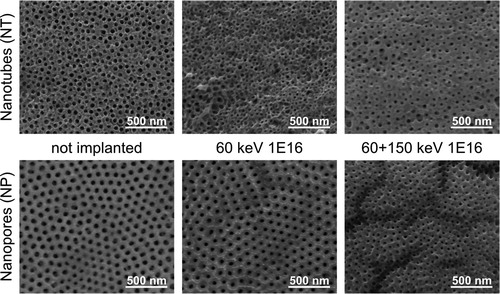
The SEM topographs in Figure illustrate our key experimental finding: We analyzed dimensions of the NT and NP topography before and after implantation. The average outer diameters (± standard deviation) of pristine NT and NP amounted 80.3 ± 8.6 nm and 123.4 ± 9.0 nm, while the inner pore diameters were averaged to 55.1 ± 3.2 nm and 66.5 ± 5.4 nm, respectively. After applying a fluence of 1 × 10¹⁶ ions/cm2 the walls of single standing NT merge and diameters decrease. By combining 60 keV and 150 keV with a fluence of 1 × 10¹⁶ ions/cm2 each, the NT morphology changes to a pore-like structure. NT pore diameter drastically decreases by 44% to 30.9 ± 8.3 nm. NP arrays show similar tendencies, at a fluence of 1 × 10¹⁶ ions/cm2 at 60 keV the pore diameter decreases by 45% to 36.6 ± 5.5 nm, whereas the wall thickness increases. The combined implantation of 60 keV and 150 keV induces further closure of the pore diameter to 29.1 ± 7.8 nm. In NP arrays, pore shrinkage is accompanied by the formation of groove-like surface patterns on a length scale approximately an order of magnitude larger than the NP (see Figures S1 and S2 in Supplemental Material). It is reminiscent of crack nucleation, and it occurs most prominently after dual implantation (60 keV + 150 keV), but also—at a reduced level—after single implantation (60 keV) with a fluence of 1016 ions/cm2, respectively.
60 keV implantation yielded dopant enrichment in proximity of the surface (depth ≈ 125 nm), whereas with dual implantation of 60 keV + 150 keV a reasonably uniform dopant (Figure (a and b)) and defect (Figure (c), Figure S3 in Supplemental Material) concentration throughout a moderate depth (≈350 nm) of the arrays was achieved. Using dual implantation with a total fluence of 2 × 10¹⁶ ions/cm2 a typical defect dose of ≈4 displacements per atom (dpa) is reached.
Figure 2. Dual implantation of 60 keV and 150 keV carbon ions into a unit cell of a hexagonally arranged NP array, as modelled with a customized version of IRADINA [Citation23], see Supplemental Material. While (a) and (b) illustrate the resulting implantation profile, the atomic displacement and relocation distributions along the target depth as function of nanotube diameter are depicted in (c) and (d). Negative and positive values in (d) correspond to atom removal and deposition; ion and recoil transport through the vacuum of the NP, as well as relocation of material by sputtering and redeposition that are also included.
![Figure 2. Dual implantation of 60 keV and 150 keV carbon ions into a unit cell of a hexagonally arranged NP array, as modelled with a customized version of IRADINA [Citation23], see Supplemental Material. While (a) and (b) illustrate the resulting implantation profile, the atomic displacement and relocation distributions along the target depth as function of nanotube diameter are depicted in (c) and (d). Negative and positive values in (d) correspond to atom removal and deposition; ion and recoil transport through the vacuum of the NP, as well as relocation of material by sputtering and redeposition that are also included.](/cms/asset/f9f72a07-3854-40cf-a82c-3c4c03ecd216/tmrl_a_1976294_f0002_oc.jpg)
During implantation, we limited the ion current to keep the substrate temperature below an estimate of 50°C to reduce temperature-induced crystallization. Moreover, sputtering near the surface is expected to be insignificant. As shown in Table , for the example of a NP array, sputtering yield proves to increase with increasing pore/tube diameter for implanting both 60 keV and 150 keV C ions, but, is generally at a very low level and thus of negligible relevance. In fact, for the maximum fluence (2 × 10¹⁶ ions/cm2) only about 2–7 atomic layers are expected to be sputtered.
Table 1. Effective sputtering yield determined for a complete hexagonal nanopore unit cell (Figure ) as function of pore diameter and ion energy, as obtained with IRADINA [Citation23], detailed in supplemental material.
In terms of mechanism accompanying implantation, increased sputtering yields are expected within the NT/NPs due to gracing incidence angles of the ions and their intersection with collision cascades. A detailed description of these processes can be found in Kupferer et al. [Citation24]. In short, particles sputtered from the NT/NP walls will be redeposited, predominantly deeper within the NT/NPs; sputtering and redeposition thus constitute a translational ballistic transport mechanism through vacuum and can be regarded as the manifestation of relocations—just as relocations within collision cascades within a solid. The net effect of both manifestations of relocations are visualized in Figure (d), that can be described by a ballistic material transport from the surface of the NT/NP array towards the interior. However, in terms of magnitude ballistic transport is not dominant, yielding only a volume change less than 0.4% for the maximum doses applied presently and thus particularly cannot explain the observed NT/NP shrinking. We therefore hypothesize that a different mechanism is at play; viz. radiation induced viscous flow whose relevance in many instances was proposed by us previously [Citation25].
Radiation induced viscous flow as morphology shaping mechanism
Molecular dynamics calculations
To get a grasp of the physics underlying implantation inducing NT and NP shrinking, two different types of unit cells of hexagonally arranged titania NT and NP arrays with a height of 61 Å as well as outer and inner diameters of 272.8 Å and 208 Å, respectively, were prepared in accord with different types of morphologies observed experimentally [Citation8]. Periodic boundaries with either zero stress in all spatial directions or only along the NT/NP axis were applied to mimic freestanding and substrate-attached arrays, respectively. Ion implantation at 300 K is modelled as insertion of displacement induced Frenkel pairs at random locations within the cell; the latter is consequently quantified in terms of defect dose, Φ, viz. displacements per atom (dpa).
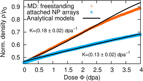
As visualized for freestanding arrays in Figure as well as Videos S-V1 and S-V2, NT and NP arrays reveal a pronounced densification with increasing defect dose, that is manifested by a shrinking inner tube diameter and can be quantified by the volume reduction of the unit cell, or, equivalently, volume density, ρ. The latter is exemplarily plotted as a function of dose in Figure for a freestanding and substrate-attached NP array; as the corresponding curves for densification of NT arrays do not reveal a qualitative difference except for slightly faster densification, they are not shown here for clarity.
Figure 3. Configurational snapshots of two dimensional cross sections normal to the pore axis taken from three dimensional simulations of NT and NP arrays with shrinking diameter as function of introduced defect density are shown. Titanium atoms are grey, oxygen is purple. The size of the unit cell decreases with progressing pore closure since zero stress is maintained in all spatial directions.
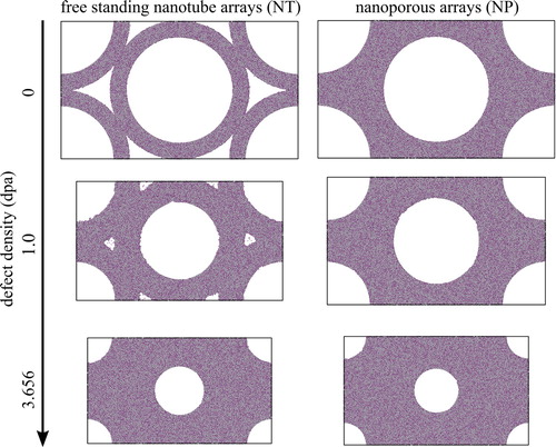
Figure 4. Evolution of density ρ normalized to the density of the non-porous solid ρ0, as a function of dose Φ for freestanding and substrate-attached NP arrays. While the individual data points are directly extracted from MD runs, the solid lines represent fits to the continuum model predictions.
Analytical continuum model
We previously reported that radiation-induced point defects induce viscous flow in metallic glasses [Citation24]. Hence, we suspect a similar mechanism to be at play presently. Based on this hypothesis, we first probed, whether radiation-induced point defects can induce viscous flow also in titania. As presented in detail in Supplemental Material (see Figures S4 and S5), this surmise not only proves to be true, but the radiation-induced fluidities η−1 = (2.831 ± 0.002) (GPa dpa)−1 for unconstrained cells are in good quantitative accord with the universal value of ≈3 (GPa dpa)−1 proposed by us back in 2003 [Citation24]. However, in contrast to unconstrained cells, biaxially constrained cells (that reflect substrate-attached systems) reveal a reduced fluidity of only η−1 = (1.26 ± 0.1) (GPa dpa)−1 due to self-induced shear stresses generated by interaction of the finite defect formation volume with the biaxial boundary constraints.
Our demonstration and quantification of radiation-induced viscous flow in titania clearly suggests pore closure to be driven by capillarity, viz. surface stress f, paired with radiation-induced viscous flow. We challenge this notion by employing two continuum models—one for substrate-attached and the other one for freestanding NP array—that are based on the assumption of an incompressible fluid, subject to Newtonian flow. For substrate-attached NP arrays, the problem has already been solved (nevertheless within a completely different scope) by Scherer and Garino [Citation26], who predict for the temporal evolution of density
(1)
(1) where
and r2 denotes the outer radius of the pore, assumed to be constant.
Analogous, we derive in Supplemental Material for freestanding NP arrays with zero average stress in every spatial direction
(2)
(2) where r10 = r1(Φ = 0) denotes the inner radius of the pore prior to irradiation treatment.
Both equations—(1) and (2)—are fitted to the MD data in Figure with reasonable agreement; deviations primarily occur in the limit of high ion fluences, respective displacement doses (Figure ), which does not seem to be a large surprise, as the geometry proves to be increasingly at odds with the model assumptions. Excellent agreement between fit and MD data can be obtained at reasonably moderate doses (Φ ≤ 2 dpa), yielding the fit values for K given in Figure .
As a summary, Table compares the continuum model predictions for K with these fit data for K, yielding an excellent agreement. The latter clearly corroborates the hypothesis that capillary driven radiation-induced viscous flow governs morphological evolution.
Table 2. Comparison of continuum model predictions and fit, assuming radiation induced viscous flow as governing mechanism. f, η, r10, r2 are extracted directly from MD.
Groove formation in NP arrays—an Asaro-Tiller-Grinfeld-Srolovitz instability?
We now focus on groove formation that occurs on a length scale about an order of magnitude larger than the pore radius and accompanies shrinking in NP arrays (see Figures S1 and S2 in Supplemental Material). As the nanotubes exert a tensile stress on the NP array, which constitutes a coherent entity just as a thin film or layer (in contrast to NT arrays that are incoherent), the Asaro-Tiller-Grinfeld-Srolovitz (ATGS) instability provides a promising candidate for its physical origin [Citation27–29]. While in the original works stress introduces an additional contribution to the chemical potential that biases surface diffusion and counteracts curvature driven smoothing, the formally very same scenario is expected to occur in presence of surface viscous flow [Citation30]. In presence of stress-induced roughening and curvature induced surface smoothing, both mediated by two-dimensional transport along the surface, the initial length scale of groove formation is given by
(3)
(3) where B, σ and γA denote the biaxial modulus, stress and surface energy of the NP array, respectively. To check the plausibility of our hypothesis that an ATGS instability governs groove formation in NP arrays, we estimate σ ≈ γ/r = 0.07 GPa (using a tube radius r ≈ 15 nm and employing the MD result for γ ≈ 1 J/m2; in presence of radiation induced viscous flow we assume γ = f for high enough fluences here – see Supplemental Material), γA ≈ γ/2 (approximately half of the surface consists of NP) and insert B ≈ 2 GPa4, yielding λ ≈ 850 nm. As this is just about the characteristic length scale of the groove pattern, it strongly corroborates that an ATGS instability is, in fact, at play.
Conclusions
To conclude we have demonstrated the capabilities of ion bombardment for tailoring the fine structure of nanotube arrays by changing the pore size. This scenario is reproduced by extensive molecular dynamics calculations that hint at implantation induced viscous flow due to defect generation. While demonstrated experimentally, analytical continuum models quantitatively confirm the nanoarray density evolution as a function of defect dose. Hence, a completely consistent picture of experiments, computer modelling and theory is provided. Pore shrinking in NP arrays is accompanied by the formation of a groove pattern that is identified as a potential Asaro-Tiller-Grinfeld-Srolovitz instability. Thus, ion bombardment constitutes a highly versatile tool for modifying the nanotube or nanopore morphology in a postprocessing approach. As future vision, we regard spatially resolved patterning using a focused ion beam or templates as a promising next step for additional novel functionality.
Supplemental Material
Download Zip (11.3 MB)Acknowledgements
The experimental part of this research was performed within the Leipzig Graduate School of Natural Sciences ‘BuildMoNa'. We acknowledge support from Leipzig University for Open Access Publishing.
Disclosure statement
No potential conflict of interest was reported by the author(s).
Additional information
Funding
References
- Roy P, Berger S, Schmuki P. TiO2 nanotubes: synthesis and applications. Angew Chem Int Ed. 2011;50:2904–2939.
- Regonini D, Bowen CR, Jaroenworaluck A, et al. A review of growth mechanism, structure and crystallinity of anodized TiO2 nanotubes. Mater Sci Eng R. 2013;74:377–406.
- Sopha H, Tesar K, Knotek P, et al. TiO2 nanotubes grown on Ti substrates with different microstructure. Mater Res Bull. 2018;103:197–204.
- Fischer K, Mayr SG. In-plane mechanical response of TiO2 nanotube arrays – intrinsic properties and impact of adsorbates for sensor applications. Adv Mater. 2011;23:3838–3841.
- Roguska A, Belcarz A, Zalewska J, et al. Metal TiO2 nanotube layers for the treatment of dental implant infections. ACS Appl Mater Interfaces. 2018;10:17089–17099.
- Kallendrusch S, Merz F, Bechmann I, et al. Long-term tissue culture of adult brain and spleen slices on nanostructured scaffolds. Adv Healthcare Mater. 2017;6:1601336.
- Mayazur Rahman S, Reichenbach A, Zink M, et al. Mechanical spectroscopy of retina explants at the protein level employing nanostructured scaffolds. Soft Matter. 2016;12:3431–3441.
- Dallacasagrande V, Zink M, Huth S, et al. Tailoring substrates for long-term organotypic culture of adult neuronal tissue. Adv Mater. 2012;24:2399–2403.
- Paramasivam I, Jha H, Liu N, et al. A review of photocatalysis using self-organized TiO2 nanotubes and other ordered oxide nanostructures. Small. 2012;8:3073–3103.
- Cho IS, Choi J, Zhang K, et al. Highly efficient solar water splitting from transferred TiO2 nanotube arrays. Nano Lett. 2015;15:5709–5715.
- Chen B, Hou J, Lu K. Formation mechanism of TiO2 nanotubes and their applications in photoelectrochemical water splitting and supercapacitors. Langmuir. 2013;29:5911–5919.
- Zhou X, Häublein V, Liu N, et al. TiO2 nanotubes: nitrogen-ion implantation at low dose provides noble-metal-free photocatalytic H2 – evolution activity. Angew Chem Int Ed. 2016;55:3763–3767.
- Chatzitakis A, Grandcolas M, Xu K, et al. Assessing the photoelectrochemical properties of C, N, F codoped TiO2 nanotubes of different lengths. Catal Today. 2017;287:161–168.
- Liu N, Häublein V, Zhou X, et al. “Black” TiO2 nanotubes formed by high-energy proton implantation show noble-metal-co-catalyst free photocatalytic H2-evolution. Nano Lett. 2015;15:6815–6820.
- Ghicov A, Macak JM, Tsuchiya H, et al. Ion implantation and annealing for an efficient N-doping of TiO2 nanotubes. Nano Lett. 2006;6:1080–1082.
- Ghicov A, Macak JM, Tsuchiya H, et al. TiO2 nanotube layers: dose effects during nitrogen doping by ion implantation. Chem Phys Lett. 2006;419:426–429.
- Panepinto A, Cossement D, Snyders R. Experimental and theoretical study of the synthesis of N-doped TiO2 by N ion implantation of TiO2 thin films. Appl Surf Sci. 2021;541:148493.
- Schindelin J, Arganda-Carreras I, Frise E, et al. Fiji: an open-source platform for biological-image analysis. Nat Methods. 2012;9(7):676–682.
- Matsui M, Akaogi M. Molecular dynamics simulation of the structural and physical properties of the four polymorphs of TiO2. Mol Simul. 1991;6(4-6):239–244.
- Wolf D, Keblinski P, Phillpot SR, et al. Exact method for the simulation of coulombic systems by spherically truncated, pairwise r−1 summation. J Chem Phys 1999;110(17):8254–8282.
- Gear CW. Numerical initial value problems in ordinary differential equations. Prentice-Hall Series in Automatic Computation; 1971.
- Mayr SG. Activation energy of shear transformation zones: a key for understanding rheology of glasses and liquids. Phys Rev Lett. 2006;97(19):195501.
- Borschel C, Ronning C. Ion beam irradiation of nanostructures – a new 3D Monte Carlo simulation code. Nucl Instr Meth Phys Res B. 2011;269:2133.
- Kupferer A, Holm A, Lotnyk A, et al. Compositional patterning in carbon implanted Titania nanotubes. Adv Funct Mater. 2021;31:2104250.
- Mayr SG, Ashkenazy Y, Albe K, et al. Mechanisms of radiation-induced viscous flow: role of point defects. Phys Rev Lett. 2003;90:55505.
- Scherer GW, Garino T. Viscous sintering on a rigid substrate. J Am Ceram Soc. 1985;68:216–220.
- Asaro RJ, Tiller WA. Interface morphology development during stress corrosion cracking. Part I. Via surface diffusion. Metall Mater Trans B. 1972;3(7):1789–1796.
- Grinfeld MA. Instability of the interface between a nonhydrostatically stressed elastic body and a melt. Dokl Akad Nauk. 1986;290:1358–1363.
- Srolovitz DJ. On the stability of surfaces of stressed solids. Acta Metall. 1989;37(2):621–625.
- Vauth S, Mayr SG. Relevance of surface viscous flow, surface diffusion, and ballistic effects in keV ion smoothing of amorphous surfaces. Phys Rev B. 2007;75:22.