
 ?Mathematical formulae have been encoded as MathML and are displayed in this HTML version using MathJax in order to improve their display. Uncheck the box to turn MathJax off. This feature requires Javascript. Click on a formula to zoom.
Abstract
The harmonic structure is a recently introduced concept paving the way for engineering metallic materials to achieve excellent mechanical performance. They consist of soft coarse-grained regions (Core) that are three-dimensionally surrounded by a connected network of hard ultra-fine grained regions (Shell). The interaction in these Core–Shell regions produces a synergistic effect, during plastic deformation, leading to superior mechanical properties that are extremely important in practical applications. The current review paper is aimed at providing a critical assessment on this novel concept of microstructure design. It also involves the identification and critical discussion of key issues which deserve additional studies.
GRAPHICAL ABSTRACT

1. Introduction
The development of materials science is indispensable for building a sustainable, safe and secure society. In particular, metallic materials have enriched our lives. In the field of metallic materials, extensive research over the past several decades has established the importance and role of dislocations on the development of the science of strengthening materials. Furthermore, significant advancement has been made on the effect of interlinking of dislocations and microstructural features, such as grain size and its distribution, on strengthening metallic materials. However, the continued emergence of new discoveries and expansion of the unknown world of materials has been providing a sustained driving force for the persistent and challenging research efforts to enrich our understanding on metallic materials. Particularly, continued discoveries, that overturn conventional wisdom, have been made one after another. For example, the conventional Hall-Petch relationship, as presented in most of the textbooks, states that the strength is proportional to the reciprocal of the square root of the grain size. However, the Hall-Petch relationship has recently been found to have an extra hardening phenomenon, which shifts from the proportional relationship to the high strength side at submicron sizes [Citation1–3]. Another example could be the occurrence of the yield point depression phenomenon in aluminum, which is generally observed only in steels [Citation2].
In recent years, there has been a great emphasis on the development of stronger and more flexible metallic materials, leading to smaller and lighter structural materials which would directly contribute to resource and energy conservation, reduction of carbon dioxide emissions, and so on. Therefore, a lot of research has been carried out to make materials stronger and tougher. However, the major barrier standing in the way is the trade-off between strength and ductility, wherein higher strength is achieved at the expense of ductility. The challenge to overcome this problem, which is said to be the fate of conventional metallic materials, has begun with a new concept of ‘hetero-structure design’, which stems from nature. In nature, there are countless heterostructures in our daily life, such as the microscopic laminated structure of shells, the honeycomb structure of beehives, and the fiber structure of plants, where both ‘strength and toughness’ are demonstrated.
The ‘hetero-structure design’ enables to achieve both high strength and high ductility, i.e. ‘strength and toughness’, in structural metallic materials [Citation3,Citation4]. High strength and high toughness are directly related to weight reduction, resource-saving, energy-saving, high reliability, etc., because the target mechanical properties can be achieved with reduced cross-section. ‘Hetero-structure design’ is different from the conventional microstructure design method, which aims at ‘more uniform and homogeneous microstructure design’. Harmonic microstructure, bimodal microstructure [Citation5], lamellar (layered) microstructure [Citation6], and surface refinement microstructure [Citation7] are well-known heterostructures, where a common histologic feature is grain size gradient. In the well-known lamellar structure, grain size gradients exist in the stacking direction, whereas isotropic grain size gradients are arranged periodically in three dimensions in the relatively new harmonic structure. The above-mentioned smart heterostructures aim to achieve both strength and toughness, and could lead to the development of new structural metallic materials by resolving the ‘paradox of strength and ductility’, which has been a barrier experienced by conventional materials.
This paper presents the development and evaluation of metallic materials with a novel and controlled heterostructure called ‘harmonic microstructure’, and introduces the mechanism of balancing ‘strength and toughness’ by harmonic microstructure control. In addition, the effect of such microstructural design on the various aspects of metallic materials and the mechanism involved thereof has been comprehensively discussed.
2. An idea that overturns conventional wisdom
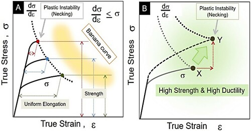
Figure shows a schematic diagram of the true stress/strain lines for material A, which shows a similar work hardening rate even with higher strength, and material B, which shows an increase in work hardening rate with higher strength. If the work-hardening rate is not increased, the higher is the strength of material A, the more plastic instability occurs at lower strains, and cracking begins. In other words, if work hardening is at the same level, the higher is the strength, the lower is the ductility. This is the reason for a trade-off between strength and ductility in conventional materials. On the other hand, if the work-hardening rate is increased along with high strength, as in material B, both tensile strength and ductility increase as the starting point of plastic instability changes from X to Y. The area of the stress/strain diagram indicates the energy absorbed by the material before fracture, i.e. the toughness. Therefore, such high-strength and high-ductility materials are also high-strength and high-toughness materials at the same time. The idea of increasing the work hardening of the material and controlling the microstructure so that uniform elongation can be maintained up to higher strains is the starting point for the development of high-strength, high-ductility, and high-toughness materials.
Figure 1. A schematic illustration of relationships between true stress/strain diagram and work hardening rate curve from tensile test.
3. A new method of microstructure control: harmonic microstructure
Then, how can we control the microstructure so that work hardening is increased? Recently, from the viewpoint of microstructure control, the heterogeneous (hetero-) structure materials, which are different from the conventional homogeneous (Homo) structure materials, have been attracting attention [Citation3]. In materials with a single-phase and uniform grain size, such as pure metals, it is difficult to achieve both high strength and high ductility/toughness because plastic instability occurs early even when the strength is increased, as mentioned above. In contrast, it has become clear that hetero-structured materials can achieve both high strength and high ductility/toughness. In addition to work hardening, there are materials exhibiting high strength and ductility due to Transformation Induced Plasticity (TRIP) [Citation8] and Twinning Induced Plasticity (TWIP) [Citation9]. However, these occur only in a limited number of materials. Work hardening, which occurs in all metallic materials, is a universal phenomenon and is extremely important. The work hardening is closely related to the generation and accumulation of dislocations. In the Homo materials, work hardening progresses mainly at grain boundaries and their vicinity, while in the hetero-materials, such as the harmonic structure (HS) materials, work hardening is larger than in the Homo materials because the generation and accumulation of dislocations are accelerated. Hence, the hetero deformation-induced (HDI) strengthening takes place by increased geometrically necessary dislocations (GND) in the soft phase side close to the heterostructure interface [Citation4].
As shown in Figure , the HS is a collection of units in which the hard phase (fine-grain structure), called the shell, envelops the soft phase (coarse-grain structure), called core [Citation10]. Each unit is originally a metal powder that has been severe-plastic deformed (SPDed) on the surface by ball milling, attrition, high-pressure gas jet milling, shot peening, and other methods. When such SPD is carried out, dislocations are repeatedly introduced and grains are divided by plastic deformation near the surface of the powder, and finally, an ultra-fine grain structure with nanoscale is formed. The power unit with a nanocrystal grain structure near the surface and a coarse grain structure inside is sintered to fabricate HS material. This process is an application of conventional powder metallurgy and is highly versatile.
Figure 2. Schematic diagram of a harmonic structure material [Citation10].
![Figure 2. Schematic diagram of a harmonic structure material [Citation10].](/cms/asset/87793c57-76a5-4035-9c0c-d8e041769d5d/tmrl_a_2057203_f0002_ob.jpg)
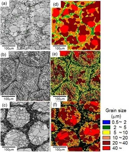
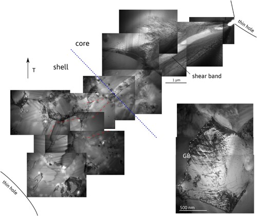
As a result of the HS design of various pure metals and alloys, it has become clear that the HS can be classified into three patterns based on differences in the microstructure formation process [Citation11]. Figure shows examples of these three classifications. The left column (a), (b), and (c) are IQ (Image Quality) images by EBSD (Electron Back Scatter Diffraction), and the right column (d), (e), and (f) are grain size images showing the difference in grain size. The first classification is the case of pure metals and single-phase alloys, which are the ‘grain growth type’ where fine-grained shells are formed by the growth of nanocrystalline grains generated by surface SPD. Figures (a) and (d) show examples of pure titanium belonging to the ‘grain growth type’. The second type of classification is the ‘diffusion transformation type’, which involves the precipitation of a second phase occurring in multi-phase alloys. Metal powders are rapidly solidified during production by atomization and other methods. In the SPD processed powders, grain growth, recovery, recrystallization, and precipitation of the second phase occur simultaneously during the sintering process. In the ultrafine-grained structure, the two-phase structure is formed in a shorter time than the precipitation by normal heat treatment because the grain boundary area is large. The diffusion of solute elements is fast in the ultrafine-grained structure and there are large numbers of nucleation sites for the second phase. Therefore, precipitation occurs first at the top surface consisting of the nano-grain structure of the powder, which finally becomes a shell after sintering. As a result, a slightly larger fine-grained shell is formed outside the ultrafine-grained shell. These are called ‘Mid-Shell’ and ‘Outer-Shell’. Figures (b) and (e) show examples of a Ti-6Al-4V (Ti64) alloy, where clear Mid-Shell and Outer-Shell can be observed. The third classification is the ‘deformation-induced transformation type’, in which the phase transformation occurs due to the surface SPD. In the SUS304L metastable austenitic stainless steel shown in Figures (c) and (f), processing favors martensitic transformation, and a fine-grained structure is formed on the surface of the powder. After that, it undergoes reverse transformation to austenite by sintering to form a fine-grained shell. The characteristic of this type is that it requires only a short period of SPD processing. A Co-Cr-Mo alloy, which is often used for medical devices, falls in this type [Citation12]. In all of these cases, the final grain size gradient is bimodal and composed of fine-grain Shell and coarse grain Core. The Shell is periodically developed in three-dimensional space. The recent brief assessment of achievements in understanding HS materials and their applications has been recently published [Citation4,Citation13]. However, it requires a more comprehensive update in view of recent publications.
Figure 3. Three classifications of the harmonic structure. (a), (d): pure titanium, (b), (e): Ti64 alloy, (c), (f): SUS304L.
4. Mechanical properties of HS materials
Figure shows a tensile strength-elongation balance diagram of SUS316L stainless steel compacts. Black square plots indicate strength and elongation balance line of the homogeneous (Homo) structure SUS316L with different grain sizes, and grey circles indicate the harmonic structure SUS316L with different ultra-fine grain (UFG) Shell fraction. As can be seen, the homo counterpart shows a typical ‘Banana curve’ which proves the strength-ductility paradox. It is noteworthy that the HS compact also shows a tendency of the strength-ductility paradox, though its strength-ductility balance is much superior to the Homo counterpart. In addition, almost the half of UFG fraction in HS compacts seems to have the best strength-ductility balance, and it is interesting that the law of mixture is not applicable to the tensile property of the HS compact.
Figure 4. Tensile strength-elongation balance of SUS316L compacts.
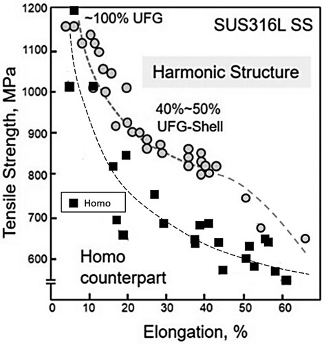
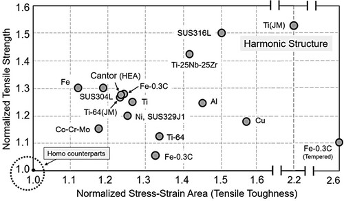
Figure shows the results of tensile strength and tensile toughness of various HS compacts, normalized by the data of each Homo counterpart compacts. The tensile toughness was evaluated as the absorbed energy to failure, which was calculated from the area of the stress–strain curve of the tensile test. Both normalized tensile strength and normalized toughness of all the HS compacts exceeded the value of 1.0 for the standard Homo counterparts, indicating that strength, ductility, and toughness were improved simultaneously. These data are not necessarily the results of the highest values, but they vary much depending on the grain size of each of the components of the HS compacts, i.e. Shell and Core, the fraction of Shell, and the sizes of the Shell/Core unit. For example, in the case of pure titanium, the result of ‘Ti (JM)’ produced by the high-pressure gas jet milling shown at the upper right end of the figure shows better properties than the result of ‘Ti’ shown in the middle of the figure, due to both smaller grain size and unit and larger Shell fraction [Citation14]. Many researches on the HS materials have proven the compatibility of strength and ductility at the same time [Citation15–25].
Figure 5. Mechanical properties of various harmonic microstructure materials.
The details of these mechanical properties are shown in Figure in the case of pure Ni HS compact [Citation4]. Figures (a), (b), (c) and (d) show the IQ image at low magnification, the inverse pole figure image at high magnification, the tensile test results, and the work hardening rate curves calculated from the tensile test results, respectively. In the case of pure Ni, a harmonic microstructure is also formed, and from Figure (b) it can be seen that the Shell has an ultrafine-grained structure. The shell average grain size is 2.3 µm, while the core average grain size is 29.2 µm. The shell area ratio is approximately 45%, while the grain size of the Homo counterpart compact is 2.8 µm. From the tensile test results of the Homo and the HS compacts, it can be seen that the later has higher tensile strength, and also better ductility and toughness. It is worth noting that although there is no significant difference in yield strength between the two compacts. The HS compact shows greater work hardening, as mentioned above, resulting in superior mechanical properties. This result of superior mechanical properties due to larger work hardening is a universal characteristic common to the various HS compacts as shown in Figure .
Figure 6. Microstructure and tensile test results of pure Ni HS and Homo compacts.
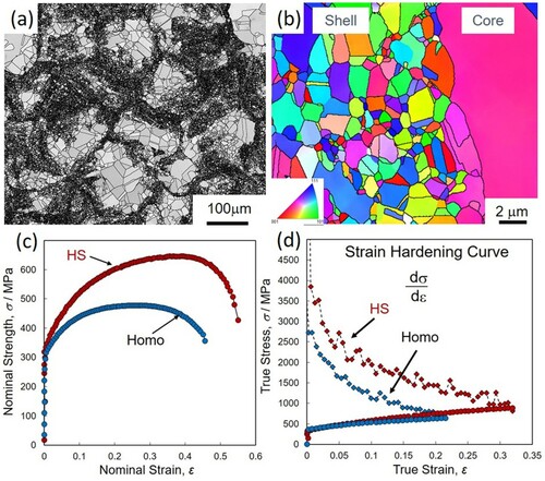
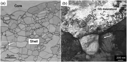
Figure is an EBSD and a TEM images showing the microstructure change during deformation. These images were taken after tensile deformation of pure Ni harmonic material by 5%. After TEM thin foil was prepared, the EBSD IQ image (Figure (a)) was obtained, and the TEM image (Figure (b)) was captured from the area indicated by the white dotted square in Figure (a). The white arrows in Figure (a) and (b) pointing to the same Shell grain. Although the shell average grain size is 2.7 µm, a slightly wide grain size spread in the shell can be confirmed. Many GNDs are observed especially in the grain boundary region. Hence, it implies that comparatively harder shell also plays an important role in the dislocation generation.
Figure 7. An EBSD and a TEM images showing the microstructure after tensile deformation of pure Ni harmonic material by 5%.
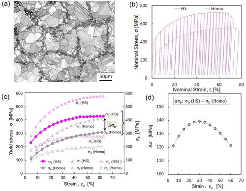
Such unusual GND accumulation can generate large back stress near the Shell and Core interface regions. Figures (a)–(d) indicate results of unloading-reloading tests of a HS and a Homo SUS304L stainless steels. As shown in Figure (a), the HS sample has a typical Shell (UFG) network structure, and average Shell grain size and Core grain size are 1.3 µm and 16.2 µm, respectively, and the Shell fraction is 22.6%. The average grain size of the Homo sample has been measured to be 31.7 µm. Figures (b) and (c) indicate the results of the unloading-reloading test, which has followed experiments reported by M. Yang [Citation26]. Those σr, σu and σb represent ‘reload stress’, ‘unload stress’ and ‘back stress’, respectively. These stresses have been calculated using 20% slope reduction from effective Young’s modulus. Figure (d) indicates differences in the back stress values, Δσb, between HS and Homo samples, and it is noteworthy that Δσb rapidly increases in the early stage of deformation and then decreases to almost the same at the end of the deformation. There should exist a different deformation mechanism in the early stage of deformation of those samples. Although the average grain size of the HS-Core is approximately half of that of the Homo, the rapid increase of Δσb seems not to be attributed to the grain size difference. The drastic increase in Δσb implies that many GNDs could have generated in the characteristic Shell network structure and its neighborhood. Thus, strain hardening can be enhanced more in the HS sample compared to the Homo counterparts. Yang et al. [Citation26] have pointed out that a stress transit, from compressive lateral stress to tensile lateral stress in nanolayers of a nano-coarse grain layer structured interstitial-free steel, causes a strain gradient and thus leads to a larger strain hardening. Moreover, Nagata et al. [Citation15] have reported that the strain hardening rate of various grain-sized Homo-Ni samples is almost independent of grain size, while it strongly depends on the Shell fraction of the HS-Ni samples. It can be understood that the three-dimensional expanse of the Shell network structure has been attributed to a multiaxial stress mode and strain gradient, and such a complicated strain gradient is expected to increase a larger strain hardening. Also, Li et al. [Citation27] have confirmed the simultaneously high strength and strain hardening rate (SHR) in the HS FeMnCoCr high entropy alloy (HEA). It is reported that the enhanced strength of the HS FeMnCoCr HEA is due to the combined effect of grain size strengthening and precipitation strengthening, whereas the enhanced SHR is attributed to the hetero-deformation induced hardening as well activation and interaction of multiple deformation mechanisms within the shell.
Figure 8. (a) An initial EBSD microstructure of a SUS304L HS sample. (b) The unloading-reloading curves. (c) Change of unloading yield stress σu, reloading yield stress σr, and back stress σb. Solid and open marks represent HS and Homo samples, respectively. (d) Variation of differences of the back stress with deformation between HS and Homo samples.
5. Role of the Shell network structure
Compared to other hetero-structure materials, one of the remarkable features of the harmonic structure materials is its Shell fine-grain network [Citation4]. In order to clarify the role of the network structure, a ‘partial-harmonic’ structure in which the network structure of the harmonic structure material has been partially interrupted and subjected to tensile tests.
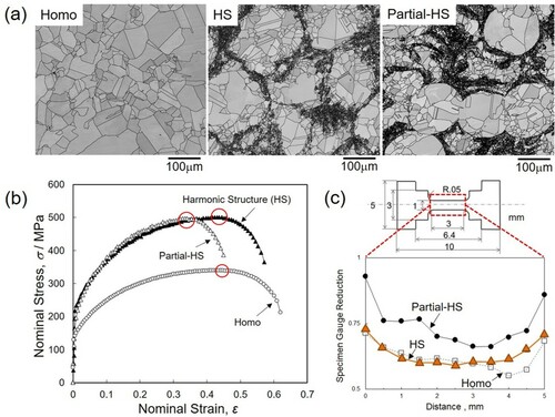
Figures (a)–(c) shows the results of a Ni case. (a) EBSD images of the Homo, the HS, and the partial-HS materials, (b) tensile test results of these materials, and (c) the results of cross-sectional reduction rate of the specimen after interrupting the tensile test near the maximum stress of both materials. Miniature specimens were used, and the gauge had dimensions of 1 mm × 1 mm × 3 mm. The shell area fractions of the harmonic and ‘partial-HS’ materials are 33.5% and 36.0%, respectively, whereas, the Core and Shell grain sizes are 31.7 µm and 35.8 µm, respectively, and the Shell grain size is approximately 3.0 µm for both materials, indicating that they have almost the same microstructure factors. However, as shown in Figure (b), both materials show similar stress–strain curves. However, the ‘partial-HS’ material has fractured early. As shown in Figure (c), in the vicinity of the strain at which necking begins, the gauge section of the harmonic material decreases almost evenly, whereas the partial-HS material shows a localized decrease in section. This suggests that if imperfections exist in the network structure, local deformation easily occurs in such imperfect regions, leading to premature fracture. This indicates that high strain hardening, and a highly complete network structure are important to obtain high strength and high ductility.
Figure 9. (a) EBSD images of the Homo, the HS, and the partial-HS materials, (b) tensile test results, and (c) the cross-sectional reduction rate.
6. Analytical and finite-element modeling of HS materials
Although great progress has been achieved in applying the HS design to different metals, the fundamental mechanisms of deformation, strengthening and damage of HS materials have not been well understood. This issue is of crucial importance in optimizing the microstructure design and quantitative prediction on mechanical properties. Analytical and numerical modeling can play an important role in these processes. In this section, we present one analytical and three finite-element models developed specifically for analyzing materials with the HS.
6.1. Analytical modeling
The analytical model for analyzing the mechanics of HS materials has been built elsewhere [Citation28]. As explained in the previous section, HS material can be presented as a continuous network of UFG phase with embedded CG phase regions (Figure or Figure (c) and (f)). For the sake of simplicity in describing the form factor of CG regions, they can be represented by circles in this work.
It is reasonable to assume that the uniaxial loading of the HS specimens leads to the elongation of CG regions in one direction along with their shrinkage in the orthogonal ones. At the same time, the areas of the UG phase in immediate contact with the CG phase deform along the CG regions while interstitial node areas (i.e. UFG regions in the triple junctions of the sintered powder particles) remain virtually undeformed. In other words, since the deformation of the UFG phase takes place along CG regions periphery, it does not contribute significantly to the change of original specimen shape.
The equation describing the dependence of effective flow stress in the HS material on strain while taking into account the volume fraction of the CG phase ρ is derived as follows [Citation28]:
(1)
(1) where ε is accumulated engineering strain in the HS specimen,
and
are the flow stresses of 100% CG and 100% UFG materials, respectively;
is a proportionality coefficient in the range
since internal stresses in the CG phase cannot exceed its flow stress;
is another coefficient also laying in the range
and proportional to the volume fraction of UFG phase deforming plastically. The magnitude of the parameters
can be found experimentally based on the accurate analysis of micro-stresses and micro-strains in the CG and the UFG phases. These can be carried out (i) on the specimen surface through the combination of electron backscatter diffraction and digital image correlation analyses or (ii) in the specimen volume through high-resolution synchrotron-based X-ray diffraction analysis.
An alternative phenomenological approach can be based on the fitting of experimental stress–strain curves using this model, which allows the calculation of strain partitioning and back stress development in the uniaxial loading of the Harmonic Structure materials of any type. The results of using this approach in the analysis of experimental data reported in [Citation29] are presented in Figure . It can be seen that HS promotes a favorable strain partitioning between the CG and the UFG phases and the build-up of back stress in the vicinity of their interfaces. In the very beginning, strain-hardening rate in the HS material is virtually equivalent to that in the CG phase. Then, it rapidly accelerates due to strain partitioning, i.e. larger strains in the CG phase, and the strain hardening of the UFG phase. These effects are further amplified by the increasing absolute value of back stress. The coefficients C1 = 0.12 and C2 = 0.43 as derived from the fitting suggest that the back stress in the HS-Ni with 40%UFG saturates at approximately 12% of a flow stress in the CG phase, while the fraction of UFG phase deforming plastically is only 0.43. The rest of the UFG phase located in the interstitial positions remains deforming elastically only.
Figure 10. Experimental stress-strain curve for HS nickel shown alongside the results of analysis based on its fitting using the eq.(1) [Citation28]. The latter reveals the evolution of stresses and strains in CG and UFG phases as well as the build-up of back stresses on the interface of core-shell regions.
![Figure 10. Experimental stress-strain curve for HS nickel shown alongside the results of analysis based on its fitting using the eq.(1) [Citation28]. The latter reveals the evolution of stresses and strains in CG and UFG phases as well as the build-up of back stresses on the interface of core-shell regions.](/cms/asset/510595e1-2615-4650-9bf8-00acdb00ca4c/tmrl_a_2057203_f0010_oc.jpg)
Thus, the practical importance of the obtained model can be defined in the abilities to (i) evaluate absolute values and stress/strain partitioning between CG and UFG phases, and (ii) estimate the magnitude of back stress along with the volume fraction of UFG phase deforming plastically. This approach to calculating back stress is very interesting since it requires a rather simple procedure based on the monotonic uniaxial testing of the HS materials and ‘calibration’ testing of 100% UFG and 100% CG counterparts, even if such calibration data are not available from the literature already. An alternative approach proposed in [Citation26] for all heterogeneous materials is based on deformation cycling, which is more complicated in practical execution, while respective data are not readily available from the literature. Nevertheless, the relative values and trends obtained using the approach [Citation26] for different materials are similar to those obtained using the model from [Citation28], as can be seen in comparative results presented in Figures and . This suggests a complementarity in the approaches giving experimentalists more universal tools for data evaluation and further analysis using more sophisticated tools for material simulations.
A software code for fitting experimental data based on the proposed model and further calculations were built in MATLAB. Now, it is made available for download at: https://www.material.lth.se/research/research-projects/hs/. Since it is reasonably user-friendly and is open access, researchers are invited for using it independently or in collaboration with the developers.
6.2. Finite-element (FE) modeling of HS materials
As the HS design is quite a new concept, relative theoretical and numerical modeling are still scarce so far in the literature. In such a landscape, even simple FE models can be very useful for developing a qualitative understanding of plastic flow and failure in the HS materials. The first 3D model of this kind was developed in [Citation30]. Although details and implications were discussed in [Citation30], the results were limited by rather a coarse meshing of the 3D-FE model.
Therefore, another 2D-FE model with the significantly higher spatial resolution was recently developed in [Citation31]. That study sheds a lot of light on the importance of topological UFG / CG distributions and the continuity of the UFG skeleton in heterogeneous materials. Representative results from the reference [Citation31] are illustrated in Figure .
Figure 11. Distribution of local equivalent strain (PEEQ) in the harmonic structure (HS) and heterogeneous (Hetero) materials with 40% UFG fraction at uniaxial tensile strain levels ε = 4% and ε = 10%. Note, at ε = 4% high-magnification areas are shown to illustrate local strain gradients, while at ε = 10% low-magnification areas are shown to cover the entire specimen cross-section with a global crack in Hetero.
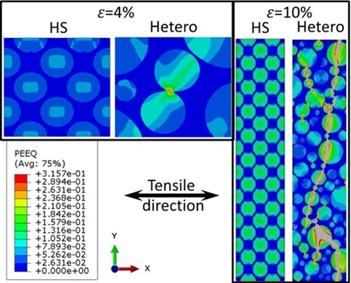
In particular, it shows that during plastic deformation, the HS material demonstrates regular (homogeneous) stress–strain distributions at macroscale along with significant local variations. While the former remains homogeneous to relatively high global strain levels, the later significantly increases in amplitude and gradient around the center of soft CG cores and their interfaces with hard continuous UFG shells. Such strain partitioning leads to strain hardening rates significantly exceeding those in homogeneous materials. The strain hardening rates are primarily controlled by the CG phase at the low plastic strains and by UFG at the larger straining. At the intermediate stages of loading, strain partitioning between increasingly constraint CG phase and hardened-to-saturation UFG skeleton, plays a key role in the composite-like material strengthening behavior. The HS design provides synergetic effect significantly exceeding expectations from the rule of mixtures, especially for material ductility.
By contrast, material lacking the HS design, i.e. simply hetero-structure, develops heterogeneities in stress–strain distributions at all scale levels (the lack of macroscale homogeneity in other words) immediately upon loading. This leads to rapidly developing strain concentrations and premature global plastic instability. These observations are consistent, and further explain the experimental results presented in Section 5 above.
Although the FE model developed in [Citation31] fully captures and explains qualitatively the experimental results, further development of FE-based models is necessary for quantitative predictions. The most advanced approach in achieving this goal is 3D Crystal Plasticity based modeling.
6.3. 3D crystal plasticity study of HS materials
Among different approaches for studying the mechanics of various materials, the crystal plasticity theory is an efficient tool for modeling the nonlinear behavior and revealing the strengthening mechanisms of these materials. Different polycrystalline models can be used in numerical analyses. The most popular method is the so-called crystalline plasticity finite element method (CPFEM) in which a real polycrystal mesh is generated by using the Voronoi tessellation method, describing the heterogeneous deformation at the levels of single grain and grains aggregate as well as the grain orientation rotation. However, the CPFEM becomes less efficient for the harmonic microstructures because of the huge contrast between the grain sizes in the core and shell regions. Under such conditions, an effective representative volume element must contain an extremely large number of grains essentially in the shell region, and this makes the finite element model excessively large.
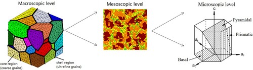
In order to overcome this difficulty, a multi-scale schema was developed for numerical analyses of the HS materials [Citation32–35]. This multi-scale approach includes essentially 3 operating levels, as schematically illustrated in Figure ;
The macroscopic level is defined by a finite element model. The finite element model can be a mono-modal or bimodal representative volume element (RVE). For the bimodal HS materials, the core and shell regions are separately meshed.
The mesoscopic level is defined at each Gauss point. At this level, a RVE including a large number of grains of different sizes is built.
The microscopic level is defined by the crystallographic slip systems in each grain.
Figure 12. Schematic representation of the multiscale approach.
At the microscopic level, the behavior of the material is taken into account through a phenomenological crystal plasticity law proposed by Méric and Cailletaud [Citation36]. The evolution of the plastic slip rate (i being the number of the current slip system) driven by the following visco-plastic evolution equation:
In this equation, and
are material parameters,
is the resolved shear stress according to the normal to the slip plane and the slip direction.
is the yield function of the
slip system defined as:
where
is the back stress and
is the critical shear stress. These variables can be considered dependent of the grain size d according to the Hall-Petch law.
The resolved shear stress on each slip system can be evaluated by using a localization model called ‘
-rule’ proposed by Cailletaud and Pilvin [Citation37–39]. According to this model, the granular stress tensor
can be related to the macroscopic stress tensor
, as follows:
where
and
are material parameters, and
denotes the volume fraction for every grain.
represents the granular plastic strain rate, tot denotes the corresponding total number of slip systems. The macroscopic plastic strain rate can be estimated as the weighted average of the granular plastic strain rate as follows:
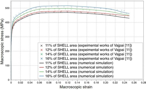
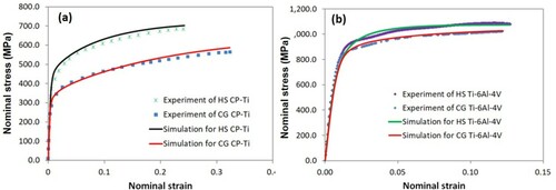
Liu et al. were the first to implement this multi-scale schema into a finite element code for the assessment of the strengthening of pure titanium caused by the HS design [Citation32]. Figure presents a FE model of the harmonic structured pure Ti RVE including 50 core regions separated by the shell regions. The volume fraction of the shell regions is controlled by the thickness of the shells. This FE model is subjected to a tensile loading. Comparison with experimental data [Citation40] is shown in Figure . From this figure, we can remark that the proposed numerical model predicts successively the constitutive behavior of HS Ti specimens under tensile loads. The agreement between the predicted macroscopic behavior and the experimental results is satisfactory. The strengthening effect of the shell region and the softening by damage evolution are correctly described.
Figure 13. Harmonic microstructure mesh.
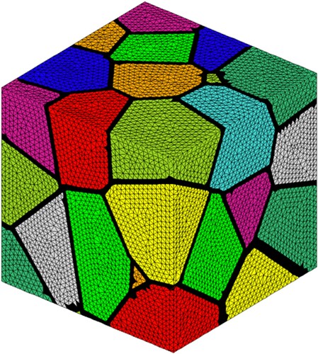
Figure 14. Simulation results and comparison experimental data.
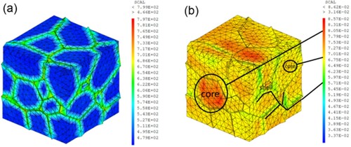
In [Citation33], a revised version of the previous model has been extended to consider the cyclic behavior of pure CG Ti and HS Ti. A nonlinear kinematic hardening rule has been introduced to represent the nonlinear stress–strain evolution and to model the Bauschinger effect. The simulation results are compared with the experimental data obtained in situ from shear tests involving cyclic loading. Figure illustrates this comparison and shows their good agreement. Figures (a), (b) show the stress and strain distributions in the RVE. We can clearly observe the sharp contrast between the stresses in the shell and in the core. On the contrary, the major deformation takes place in the core regions. These numerical results enable to highlight that the shell region contributes proportionally more to the general strength of the material while the global ductility is guaranteed by the core deformation.
Figure 15. Comparison of simulated hysteresis loops and experimental data for HS CP-Ti.
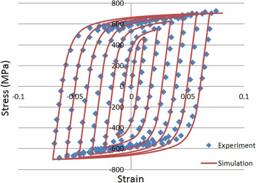
Figure 16. Distributionsc of (a) Effective shear strain fields and (b) effective strain fields in HS CP-Ti RVE.
In [Citation34], numerical simulations were performed based on crystal plasticity and beta-rule for a titanium alloy Ti64. The microstructure of this alloy is more complicated than that in pure Ti. The coarse grains (CG) are composed of α + β lamellar colonies, in which a successive stacking of α (hcp) laths and β (bcc) laths can be found as schematically shown in Figure .
Figure 17. Schematic illustrating (a) Burgers orientation relationship in lamellar α + β colonies and (b) lamellar colony length scales.
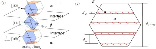
Due to the special microstructure of the α + β colonies and the Burgers orientation relation, the entire laminar α + β colony can be considered as a single super grain in the crystal plasticity analysis as proposed in Goh et al. [Citation41] and Mayeur [Citation42]. In fact, the slip systems having a slip direction intersecting the α/β interfaces are difficult to activate. The threshold stresses of these slip systems are governed by α lath width and the β rib width respectively through a Hall-Petch type relation. On the contrary, slip systems which slide parallel to the phase interfaces or bear parallel slip planes in two phases are not affected by the interfaces’ obstacles to slip transmission. Integration of these features into the crystal plasticity analysis of the super grain allows the establishment of a numerical model for HS Ti64 alloy.
Numerical simulations show that the contrast between stresses and strains in shell regions and in core regions observed in HS Ti64 is hardly noticeable (Figure ). The effect of the harmonic structure compared to coarse grains is not as pronounced as it was for pure titanium (Figure ). The different reinforcing mechanisms of the HS design on pure Ti and on Ti64 have been thoroughly discussed in [Citation4] through systematic simulation works. It has been found that for the HS materials, the fundamental sources of strengthening effect are mainly the length scale effect and the special arrangement of the FG and the CG regions. Meanwhile, the strengthening of the HS materials is also directly influenced by the grain orientations, the number of grains (or colonies) in the CG regions and the anisotropy of slip system strength. These mechanisms produce a significant enhancement of material strength for pure Ti. However, for Ti64, the improvement in the mechanical properties generated by the HS design is not as significant as expected. The main reason for this counter performance is the hard deformation mode which exists in lamellar α + β colonies when the slip direction intersects the α/β interfaces. In fact, the small microstructure lengths in lamellar α + β colonies, i.e. the widths of α and β laths are similar to the average size of equiaxed α grains in the FG regions. Therefore, the strengthening effect of the FG regions is largely hidden, resulting in a slight improvement of material strength.
Figure 18. Distributions of (a) effective shear stress field and (b) effective shear strain field at the overall strain of 12.7% predicted by the simulation for HS Ti64.
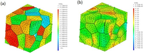
Figure 19. Stress-strain curves showing the strengthening of (a) pure Ti and (b) Ti64 caused by the HS design. The experimental and numerical data are plotted for comparison.
7. Dislocation dynamics of the harmonic structured materials
In order to assess the origin of mechanical strength, complementary observations of plastic deformation at the nanoscale were carried out in both Ti64 and Ti-25wt%Nb-25wt%Zr (TNZ: Ti-25Nb-25Zr) harmonic alloys by in-situ Transmission Electron Microscopy (in-situ TEM) [Citation43]. This technique indeed allows the observation of the dislocation dynamics while straining a thin foil. Because of the heterogeneous nature of the materials and large differences in grain sizes, observations have been mainly performed in areas containing a limited number of grains, i. e. in the shell part. In some occasions discussed below, the interface between core and shell has also been investigated. In the following, we would like to address two questions related to the exceptional mechanical behavior of harmonic alloys.
First, the origin of strengthening mechanisms at the nanoscale and their relative contributions to effective stress are discussed. It can be shown that in Ti64, despite sparse and localized observations, an estimation of the effective stress in agreement with macroscopic mechanical tests can be retrieved. Secondly, we will tentatively address the question of strain transmission between core and shell from observations at this interface in a TNZ alloy.
7.1. Mechanical strength estimation from dislocation dynamics observations in Ti64
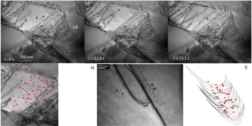
Under stress, a-type dislocations are emitted mainly at the alpha/beta interfaces although standard spiral sources can also be seen in larger grains. They move both in basal and prismatic planes but with a strong screw character, as seen in coarse grain alloys [Citation44], suggesting the existence of large lattice friction. More surprisingly here, some edge dislocations appear globally straight, while mixed dislocations are more rounded, leading sometimes to the formation of squared loops. Figure is an illustration of dislocation glide. It is composed of bright field images extracted from video sequences taken under stress. Figures (a)-(c) show the operation of a dislocation spiral source (S) in a prismatic plane, while Figure (e) is a snapshot from a mixed dislocation gliding in a basal plane. As the dislocation spirals around the source (Figures (a)-(c)), dislocation segments move forward. As the spiral is cut by free surfaces, long straight screw segments are mainly visible here. The dislocation dynamics shows that the screw parts are largely less mobile (about ten times) compared to the edge parts, as seen during the expansion of the spiral in Figure (b). Therefore, the motion of the screw is the rate-limiting mechanism. All segments exhibit a marked pining. Figures (d), (f) show the pinning points identified during the dislocation motion for both screw and edge/mixed dislocations. Interestingly, the dislocations move jerkily (see movies in the Supplementary materials), which is not expected in the case of movement controlled by lattice friction. This thus indicates that pinning should control the motion. Other mechanisms have also been reported in our observations: short-range order strengthening, and dislocation pilling at the grain boundary. The first one is typical in Ti alloys and is thought to be due to the local atomic clustering which is broken by the dislocation motion, leading to strengthening. After the passing of two dislocations that are initially paired in the virgin material (Figure (e)), the short-range order is destroyed here, and this tends to localize the deformation in bands [Citation45]. Thus, dislocation pilling at grain boundaries appears to be favored as seen for instance in Figures (a)-(c). The back stress due to these pile-ups is expected to play a role in the building of the internal stresses as revealed in the shear stress tests [Citation46]. This latter effect is expected to get enhanced in the shell because of the ease of dislocation motion in small pile-ups [Citation47].
Figure 20. (a)–(c) are images extracted from an in-situ video sequence showing the operation of a source s in a prismatic plane. The source expands when a critical distance dc is reached. a-type dislocation exhibits screw segments with pinning points along their path (marked in (d), (e)) shows a pair of mixed dislocation in the basal plane, also highly pinned (f).
The strength contribution due to these two mechanisms in the shell is far less than the yield stress (see the estimation in the Supplementary materials). Thus, the controlling mechanism could plausibly due to the dislocation pinning on solute atoms. The edge dislocations are also pinned (Figure (e)), and this indicates that this effect is strong, and contributes to a very large fraction of the effective stress [Citation48]. This solute stress can be estimated in two different ways by measuring either the mean distance between anchoring points along the line, or the critical distance for dislocation loop expansion (the distance dc in Figure (b)). Detailed calculations are shown in the Supplementary Materials. They follow an approach similar to the one described in a previous study in the harmonic structure TNZ [Citation43] and in other BCC solid solutions [Citation49]. Here, the measurements lead to an estimated effective stress ranging from 247 to 345 MPa. This has to be compared to the mechanical shear tests, which allow a partition of the stress [Citation23]. They yield to an effective stress of the order of 200 MPa at 3% strain (taking into account a typical Taylor factor of 1.5) almost constant with the deformation.
Two conclusions can be drawn here. First, in the overall, stress estimates derived at nanoscale and macroscale are of the same order, indicating that the major strengthening mechanism in the Ti64 harmonic material is due to solute hardening as in coarse grain materials. Second, the fact that stress estimated at the nanoscale is higher can be interpreted partly by a size effect, as observations are made in thin foils, and in the shell regions. Thus, we can reasonably expect that shell is stronger in virtue of a Hall Petch effect. The nature of the solute atoms/clusters is not known but is probably a combination of substitutional (Al, V) and interstitial atoms (O), that may be incorporated during powder milling.
7.2. Strain propagation at core/shell interface in TNZ
The question of strain propagation and incompatibility between the core and shell is central. Figure shows a thin foil area in a TNZ sample bridging two holes, where both shell and core are visible. Indeed, the right part is composed of a single grain, and the left part of micron size grains. Upon straining, the stress concentrates first on the right area, and rapidly leads to dense shear bands. On its border straight and pinned screw dislocations that have cross-slipped can be seen. Dislocations eventually do pile up in front of the shell region. With increased straining, the shell is deformed by emitting dislocations from grain boundaries. The inset in Figure indeed shows several slip traces originating from the left grain boundary (GB). At variance with the deformation in the core, deformation in the shell occurs by multiple slip traces that gradually fill grains. In the overall, grains in the shell are strained simultaneously far ahead of the incoming shear bands, and each grain develops several slip systems as reported by the red dotted lines in Figure .
Figure 21. Overview of deformation at the shell-core interface between two holes in a TEM foil. In the core a marked shear band develops leading to a delocalized deformation in the shell. Inset: zoom in a shell grain showing numerous slip traces from the grain boundary (GB).
From this observation we infer that, in the bulk material, large shear bands are expected to occur in conjunction with strong pile-ups and accumulation of dislocations close to the shell. This certainly would contribute to the rise of internal stresses compared to usual coarse grain materials. Eventually, the shell is supposed to yield, but with the development of a more homogeneous/delocalized plastic deformation occurring by dislocation emission from grain boundaries.
8. On the dynamic behavior of harmonic-designed materials: application to pure Ti and Ti64
As described extensively in this chapter, the study of the mechanical behavior of materials having a harmonic structure shows overall improved properties in terms of mechanical strength and ductility, compared to the conventional structures counterparts, when loaded at room temperature (R.T.), especially within the quasi-static regimes. Materials’ high strain rate behavior is essential in many applications, from microelectronics to ballistic applications, where the harmonic structures could be good candidates because of improved mechanical properties, including fatigue properties (see section 7 below). However, the study of the mechanical behavior of the harmonic structures (HS) in the regime of high strain rates (and large strains) is not standard and remains limited, both from the macroscopic point of view and from the microstructure evolution. Therefore, because of the specific microstructural characteristics of the HS-designed materials, their high strain rate behavior is worth an investigation. We have chosen to illustrate here the case of both pure titanium and Ti64 alloy because of their importance in various application fields ranging from transport to biomedical, where high strain rate loadings such as impact loading can be encountered.
8.1. Macroscopic behavior by direct impact loading of HS pure Ti and Ti64 alloy
In a previous study, Dirras et al. [Citation25] have studied mechanical behavior, and microstructural evolution of a HS designed pure Ti exposed to various strain rates (and strain). The high strain rate regime has been carried out through direct impact loading (Direct Impact Hopkinson Pressure Bar, DIHPB) condition at R.T. [Citation50]. Typical examples of the evolution of the mechanical behavior under dynamic stress of the HS-designed pure Ti are presented in Figures (a) and (c) respectively. It is interesting to note that the averaged data for all the investigated samples underlines a trend of a positive work hardening as no macroscopic softening behavior is observed (Figure (a)). The flow stress as a function of the strain rate (in logarithm scale) displays two domains, named I and II in Figure (c) (lower curve). The domain I is the so-called thermally activated regime, dominated by dislocations overcoming obstacles (see section 5 above). The second one, at a very high strain rate (the dynamic regime), is the so-called viscous domain, dominated by dislocation-phonon interactions. As in the conventional materials, it displays a substantial increase in the flow stress.
Figure 22. True stress versus true plastic deformation of the harmonic-structured (a) Ti and (b) Ti64 at R.T. (The strain rates in the dynamic regime for the different samples are shown in the inserts on figures (a) and (b), for Ti and Ti64). Evolution of the yield stress versus the strain rate of both Ti (‘Ti yield’) and Ti64 (‘Ti64 yield’) is shown in (c).
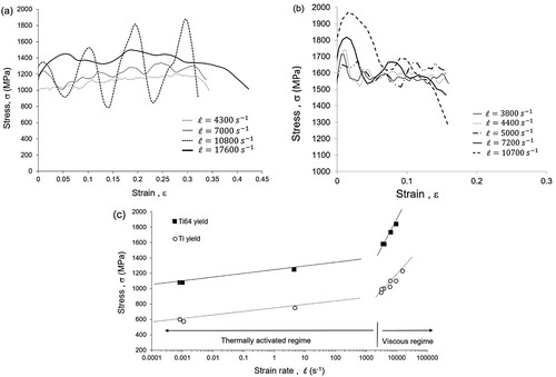
Zerilli and Armstrong [Citation51] have suggested that this behavior could be more accurately interpreted because of an increase in dislocation and twin formation rates. The transition between the two domains occurs here around 103 s−1. A similar trend is also observed in the Ti64 HS, as illustrated in Figure (c) (upper curve). These curves illustrate a very high strain hardening rate and strain rate sensitivity of the flow stress at low strains. Assuming relationship between the flow stress and the strain rate, the strain rate sensitivity of the flow stress coefficient,
, computed in these two areas are about 0.59 and 0.67, respectively, and this means a higher flow stress sensitivity of the HS Ti64 compared to the pure HS Ti in the dynamic regime.
Departing from the behavior of pure HS Ti, after a rapid hardening rate, a stress peak is quickly reached, followed by a marked drop for the HSÓ Ti64 counterpart (Figure (b)). This softening behavior can be linked to catastrophic failure by shear banding. Indeed, an analytical model proposed in [Citation52] shows that the overall hardening behavior of a material exposed to a given stress state leading to catastrophic failure can be expressed as:
Softening via shear band formation occurs when the thermal component in the above equation takes the lead over the strain and strain rate hardening effects (represented by the first and the second quantities, respectively). In the following, it is demonstrated that while adiabatic effects during dynamic loading are present in both the pure HS Ti and the HS Ti64, the softening effect is less pronounced in the HS Ti due to the peculiarities of the adiabatic shear bands (ASB) structures. Furthermore, compiled data by Zezhou et al. [Citation53] show that the conventional pure Ti possesses a higher hardening component and a lower thermal softening parameter compared to the Ti64 counterparts in the range 200–1200 K. Therefore, it is expected that the level of the thermal contribution to the macroscopic softening would be less pronounced in the pure Ti, as it is observed here in the pure HS Ti compared to the HS-Ti64 counterparts. Indeed, a study by Rittel and Wang [Citation54] have challenged the efficiency of thermal softening processing concerning ASB formation, which seems to be material dependent if the HS Ti64 and pure HS Ti are compared.
Compression tests were conducted on cylindrical specimens with a diameter of 5.9 mm and a height of 3 mm cut from the as-consolidated HS designed disks. The DIHPB set up located at Nexter Munitions (Bourges, France) was used for high strain rate loading experiments. Tests were conducted on cylindrical specimens with a diameter of 5.9 mm and a height of 3 mm cut from the as-consolidated HS designed disks. Note that this section will not discuss the thermally activated regime associated with quasi-static and intermediate strain-rate tests. More details concerning the DIHPB procedure have already been given elsewhere [Citation55].
8.2. Microstructure feature at high strain rate regime behavior DIHPB loading of HS pure Ti
As reported in various studies, Ti and its alloys usually display a microstructure dominated by the formation of localized deformation bands identified as ASB when loaded in the dynamic regime. These bands could later be the site of material softening and further ruin via crack formation. Figure compares dynamically loaded pure conventional and harmonic Ti. The formation of a straight localized deformation band (Figures (b)–(c)) believed to be of ASB-type can be observed in the pure Ti. Indeed, due to the adiabatic heating, dynamic recrystallization sets in within the localized band as illustrated by the formation of equiaxed ultra-fine grains (UFG) having a random crystallographic texture.
Figure 23. Microstructure of pure HS Ti. (a): IPF + Boundary map; (b) Homogeneous Ti after DHPB loading: IPF showing an ASB: (c) Zoom of (b); (d)–(f); DHPB loading on HS pure Ti under various conditions. Figures (g)–(i) give the details on the formation mechanism of an ASB in pure Ti. (g): IPF map; (h) Grain boundary map: (i) Grain orientation spread (GOS) map. Figure (h), in particular, reveals the presence of LAGBs, which means the UFG grains continue to bear a considerable amount of plastic deformation, as reported by [Citation25]. (See text for details).
![Figure 23. Microstructure of pure HS Ti. (a): IPF + Boundary map; (b) Homogeneous Ti after DHPB loading: IPF showing an ASB: (c) Zoom of (b); (d)–(f); DHPB loading on HS pure Ti under various conditions. Figures 23 (g)–(i) give the details on the formation mechanism of an ASB in pure Ti. (g): IPF map; (h) Grain boundary map: (i) Grain orientation spread (GOS) map. Figure 23 (h), in particular, reveals the presence of LAGBs, which means the UFG grains continue to bear a considerable amount of plastic deformation, as reported by [Citation25]. (See text for details).](/cms/asset/9a748d9f-7e48-46dd-a80c-18d6b8460ad5/tmrl_a_2057203_f0023_oc.jpg)
Nevertheless, in the case of HS Ti (Figures (d)–(f)), the deformation substructure remains dominated by twinning, and the occurrence of localized deformation bands is postponed till higher compression rates and strain rate (Figures (e)–(f)). In addition, it is interesting to note that the morphology of the localized deformation band seems to match its HS design, more specifically that of the shell. This would indicate that the stored energy necessary to trigger the recrystallization phenomenon is more significant near the shell by GNDs accumulation at the core/shell interfaces as usually observed in the quasi-static deformed HS materials (see section A). Such curved UFG rims are not observed in the conventional pure Ti. It is interesting to point out here the work by Rittel [Citation56], who emphasizes the prevalence of the dynamically stored energy (of cold work) on ASB formation.
A detailed structure of a portion of an ASB in the HS Ti is presented in Figures (g)–(i). Three regions A, B, and C having different microstructural characteristics can be identified in Figure . The region A is a portion of the core, the region B is the recrystallized part of the ASB, and the region C, which is a not yet recrystallized part, displays elongated grains indicative of intense shearing. As illustrated, both the regions A and C have a high fraction of low angle dislocation boundaries compared to the region B, which is mostly defect-free (Figures (g)–(i)).
As Wang et al. [Citation57] have reported that the various microstructure changes in ASB include dynamic recovery [Citation58–60], among others. The formation of equiaxed UFG grains via dynamic recrystallization is generally accepted [Citation61]. A rough estimation of the temperature increase during the impact loading has been computed by use of the Taylor-Quinney relationship:
Where β is the Quinney constant (0.9 is used here assuming that 90% of the plastic work is converted to heat), Wp is the plastic strain work per unit mass, ρ mass the mass density, and Cp the specific heat at constant pressure. For the actual material and experimental conditions (15,000 s−1, 90% compression strain), a value of about ΔT = 1050 K has been obtained, and this is higher than the recrystallization temperature for pure Ti (assuming a 0.4 Tm, where Tm is the melting temperature of pure Ti).
Some details in Figure allow us to underline the mechanism of formation of equiaxed grains from elongated and strongly deformed grains. In fact, it can be noted in Figure (g) that the grain G1 has an orientation close to the [2-1-10] axis and is in fact made up of ultra-fine sub-grains as shown by the same grain in Figure (f). Grain denoted G2 delineated by an ellipse, also located at the interface between elongated and recrystallized grains, is an advanced stage in structuring elongated grains into UFG grains.
Low local disorientation levels shown by the measured GOS values indicate that most UFG grains are recrystallized (blue grains). Wang et al. [Citation57] have proposed an explanation for the formation of UFG grains from elongated grains of ASB based on the rotational dynamic recrystallization concept. Indeed, Hines et al. [Citation58] have shown that the grains with LAGBs, such as G1 in our case, could rotate, causing an increase in subgrain misorientation. Thus, the elongated grains such as G1 are proposed to be the first stage of severe shear deformation and further break up into small ultrafine-grained grains. Interestingly, the UFG grains continue to bear plastic deformation, as illustrated by the high number of LAGBs shown in Figure (h), thus maintaining the overall work hardening as illustrated in Figure (a).
8.3. Microstructure feature at high strain rate regime behavior DIHPB loading of HS Ti64
Figure illustrates the case of the HS Ti64, dynamically deformed. For the sake of clarity and because of the complex microstructure, the monitoring of the microstructure evolution has been carried out by analyzing local disorientation (GOS), both from the impacted surface (perpendicular to the impact direction) and the transverse section (parallel to the impact direction).
Figure 24. (a)–(d): Microstructural evolution in terms of GOS analysis. Apart from flattening the core-shell structure (Figs. b and d), the microstructure changes little qualitatively, whatever the dynamic strain rate. (The insert represents GOS values of the initial state). (e)–(g): HS Ti64 impacted at 3600 s−1 and 50% compression strain. An ASB is seen, shearing the ultrafine-grained background microstructure formed through dynamic recrystallization. (e): SEM; (f) IPF; (g) Grain size map. (See text for details). (h-i): Heterogeneity of the deformation (view on the edge) on either side of an adiabatic shear band. Note the damage occurs within the shear band. 50% dynamic compression at a strain rate of 3800 s−1. (See text for details)
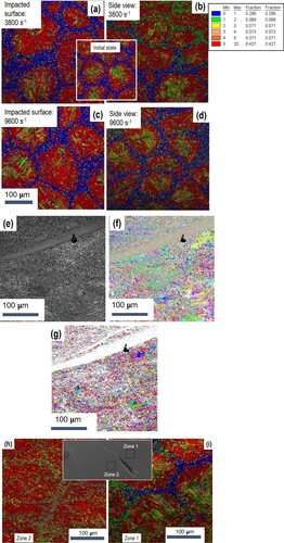
Figures (a)–(d) shows the evolution of the microstructure of the HS-designed Ti64 alloy after impacts at 3800 and 9600 s−1. Very little evolution between the two loading states has been observed. Indeed, for a fixed strain of about 20%, whatever the analyzed surface, apart from a flattening of the core–shell structure when seen on the wafer, the level of GOS parameter within or at the vicinity of the shell remains very little disturbed, on average, and thus demonstrating the stability of the 3D shell network under the applied dynamic conditions.
Figures (e)–(f) illustrate an aspect different from that previously observed. Further increase of the controlled strain at 50% has resulted in the occurrence of a deformation band which is superimposed on a microstructure made of ultra-fine grains. A GOS analysis (not presented) here shows a very high level compared to the rest of the matrix, thus indicating a strong localization of the deformation in the band. The matrix is essentially made up of ultra-fine grains exhibiting a random crystallographic texture. This very likely indicates the occurrence of dynamic recrystallization, helped by the increase of ‘cold work’ energy. This result makes it possible to affirm that the dynamic recrystallization precedes the formation of the adiabatic shear band and serves as a support for its growth. This observation agrees with a recent discussion by Rittel [Citation55], who has examined the link between thermal softening and ASB formation. Indeed, it has been shown that in the conventional Ti64 alloy, dynamic recrystallization occurs at a modest homologous temperature increase of 0.19, long before the failure by ASB. In the present case, a calculation carried out using the above equation shows that for a plastic strain rate of 3800 s−1 and a plastic strain of 2% (before the stress peak as shown in Figure (b) or of 10% after the stress peak and in the softening domain as shown in Figure (b), the temperature increase is about 14 K and 65 K, respectively. These results agree with those of Rittel [Citation55].
Figures (h)–(i) show another interesting aspect of the HS Ti64 alloy upon high strain loading. In the absence of the generalized dynamical recrystallization phenomenon as described above, the damage is observed via the formation of numerous shear bands (inclined at 45° to the impact direction). It is impossible, as it stands, to know whether the observed damage results from strain incompatibility between zone 1 and zone 2 (see the insert) or that it is the ASB that generates the microstructural heterogeneity as observed here.
To summarize, in this section, the behavior in dynamic regimes of the HS pure Ti and HS Ti64 alloy have been discussed in relation to the microstructure evolution. Under the experimental conditions of the present studies, it can be observed that some peculiarities seem to be specific to the harmonic design, while some mechanisms may be applicable in the conventional materials. One can cite, for example, the dynamic recrystallization, which takes place mainly from the shell in the case of Ti and whose capacity to take subsequent plastic deformation makes it possible to maintain a strain hardening in the material without rupture by the ASB. In the HS Ti64, the salient fact is the stability of the 3D structure of the shell, up to generalized recrystallization, which precedes the formation of the ASB. In the absence of dynamic recrystallization, a failure of the material occurs by generalized shearing, undoubtedly linked to the strain incompatibilities which are developed during straining.
9. Fatigue behavior of the harmonic structured materials
9.1. S-N characteristics
In previous sections, metallic materials with a harmonic structure (HS) have exhibited high strength and high ductility compared to their homogeneous counterparts because stress and strain localization are suppressed in the HS. Furthermore, it can be confirmed that the harmonic structured materials exhibit a superior dynamic response. We have focused on the fatigue properties of a CP titanium [Citation20,Citation62–64], a Ti–6Al–4V alloy [Citation21,Citation65–69], and an austenitic stainless steel [Citation22,Citation70,Citation71] with HS to achieve sufficient performance for practical applications in the engineering fields. This is important since most machines and structural parts are subjected to repetitive or fluctuating stress. In this chapter, we introduce the mechanism of fatigue fracture, fatigue cracks initiation and propagation, in the HS materials.
Figure shows the results of four-point bending fatigue tests for the Ti–6Al–4V alloy compacts (untreated and HS series). A stress amplitude, σa, has been applied to the specimen surface as a function of the number of cycles to failure, Nf [Citation21]. The fatigue limit, σw, for the HS series is higher than that for the untreated series. The fatigue limit tends to increase with the volume fraction of the fine-grained structure in the HS, in addition to the tensile strength and 0.2% proof stress [Citation68], and with decreasing the specimen size due to the size effect [Citation69]. Zhang et al. have reported a similar trend of fatigue properties of austenitic stainless steels with the harmonic structure [Citation22]. Furthermore, the fatigue life for the HS series is longer than those for the untreated series, although the HS series have a large fatigue life scatter. As a result of statistical analysis by applying the three-parameter Weibull distribution concept, it has been confirmed that a harmonic structure design increases the fatigue life of Ti64 alloy [Citation21]. Consequently, the harmonic structured materials exhibit superior fatigue properties rather than the material with coarse acicular microstructure.
Figure 25. Results of four-point bending fatigue tests, showing stress amplitude as a function of cycles to failure explaining that HS series (Ti64) has the higher fatigue limit and fatigue life [Citation21].
![Figure 25. Results of four-point bending fatigue tests, showing stress amplitude as a function of cycles to failure explaining that HS series (Ti64) has the higher fatigue limit and fatigue life [Citation21].](/cms/asset/85eace8f-27de-48a9-9be8-3975a3ad33aa/tmrl_a_2057203_f0025_oc.jpg)
9.2. Fatigue crack initiation
To clarify the microstructure near the crack initiation site, EBSD analysis has been conducted for the facets observed on the fracture surfaces of the HS specimen [Citation21,Citation62,Citation63,Citation66–70]. Therefore, three-dimensional fracture surfaces are produced using MeX software (Alicona) for 3D-fracture surface reconstruction to calculate the angle of the fracture surfaces. Figure shows plan views of both fracture surfaces of the HS series (Ti64). Figure shows SEM micrographs of the analysis areas and inverse pole figure (IPF) maps obtained using EBSD for both the fracture surfaces near the crack initiation site. The facets at the crack initiation sites of both the fracture surfaces are α-phase, and have the same crystal orientation with grain sizes of ca. 15 µm. This result indicates that a fatigue crack is initiated at the facet of the coarse-grained structure in the HS.
Figure 26. Plan views of the both fracture surfaces of the HS series (Ti64). (a) Fracture surface 1 (b) Fracture surface 2 [Citation68].
![Figure 26. Plan views of the both fracture surfaces of the HS series (Ti64). (a) Fracture surface 1 (b) Fracture surface 2 [Citation68].](/cms/asset/95e23c55-175e-4c1b-b66e-7657c46a8e9c/tmrl_a_2057203_f0026_oc.jpg)
Figure 27. SEM micrographs and IPF maps obtained by EBSD analysis for the facet observed in the fracture surfaces of the HS series (Ti64). (a) Fracture surface 1 (b) Fracture surface 2 [Citation68].
![Figure 27. SEM micrographs and IPF maps obtained by EBSD analysis for the facet observed in the fracture surfaces of the HS series (Ti64). (a) Fracture surface 1 (b) Fracture surface 2 [Citation68].](/cms/asset/a92cfc37-89d1-466e-bb21-42a104a76396/tmrl_a_2057203_f0027_oc.jpg)
The initiation of fatigue cracks has also been observed in the zones associated with coarse grains in other metals with the harmonic structures, including CP titanium [Citation62,Citation63] and austenitic stainless steel [Citation71]. As well, the CP titanium having ultrafine grains in which the grains are recrystallized via annealing following severe plastic deformation tends to exhibit an exceptional balance between ductility and strength. Thus, the fatigue strength of the CP titanium having a harmonic structure can be greatly improved by the refinement of coarse-grained zones. This refinement, in turn, can be accomplished by heat treatment with subsequent cold rolling, representing a type of thermo-mechanical processing (TMP) [Citation63]. The fatigue crack initiation life and the fatigue life associated with the TMP-HS samples (CP titanium) are both longer than those for the HS series when testing has been performed with the same σa value [Citation63]. Therefore, the TMP appears to improve the resistance of the HS materials to fatigue crack initiation. The paths of these cracks have been examined in detail based on EBSD data to establish the mechanism by which small fatigue cracks are initiated in the TMP-HS specimens. the IPF maps produced from EBSD data in the vicinities of crack initiation sites for the samples from both series are shown in Figure [Citation63]. Here, white lines indicate the crack profiles, although every crack seems to have started in a coarse-grained structure. The TMP-HS samples have smaller grain sizes as a result of grain refinement due to the TMP. Thus, it is apparent that the fatigue life of the CP titanium having a harmonic structure is improved by the TMP due to greater resistance to the initiation of a fatigue crack.
Figure 28. IPF maps obtained by EBSD analysis for (a) HS and (b) TMP-HS series (CP titanium) near the crack initiation sites [Citation63].
![Figure 28. IPF maps obtained by EBSD analysis for (a) HS and (b) TMP-HS series (CP titanium) near the crack initiation sites [Citation63].](/cms/asset/e348f7d2-4593-457c-887a-7061592f4888/tmrl_a_2057203_f0028_oc.jpg)
9.3. Fatigue crack propagation
In the previous section, it has been shown that a fatigue crack initiates at the coarse-grained structure in the HS. Another important aspect of the fatigue properties of the HS material is a near-threshold crack propagation dependent on the microstructure.
Figure shows the diagram of the crack growth rate da/dN against the stress intensity range ΔK, for the Untreated and the HS specimens (austenitic stainless steel) tested at various stress ratios [Citation71]. In each series, the threshold stress intensity range ΔKth tends to decrease, and da/dN increases at a given applied ΔK value with an increase of R. Furthermore, the crack growth rates for the HS series are constantly higher than those for the Untreated specimens at comparable ΔK levels. This result indicates that the resistance to long fatigue crack propagation in the SUS304L is reduced by the HS. Furthermore, the effects of the HS at near-threshold levels are attributed to crack closure and to grain size. This same effect has been previously observed for the CP titanium [Citation20,Citation72] and the Ti64 alloy [Citation65,Citation67]. In addition, the volume fraction of the fine-grained structure does not influence the fatigue threshold of the HS materials [Citation67].
Figure 29. Relationship between da/dN and ΔK for the HS and untreated series (austenitic stainless steel) tested at R = 0.1 and 0.8 [Citation71].
![Figure 29. Relationship between da/dN and ΔK for the HS and untreated series (austenitic stainless steel) tested at R = 0.1 and 0.8 [Citation71].](/cms/asset/9193b12e-87a6-4214-8ded-1f1eeaaabb88/tmrl_a_2057203_f0029_oc.jpg)
Fatigue crack paths have been analyzed to discuss the mechanism of fatigue crack growth for HS stainless steel [Citation71]. Figure (a) and (b) respectively show the SEM micrograph corresponding to the EBSD analysis area and the IPF map around the crack obtained using EBSD for the HS sample after testing at a stress ratio of 0.1. The grain size color map in the regions with grains smaller than 4 µm is shown in Figure (c), and the crack profile is shown as a white line in Figure (b) and (c). Fatigue cracks could not avoid propagation in the coarse-grained structure, and cracks also could not preferentially propagate near the fine-grained structure. These results show that the fatigue crack profile is not influenced by the HS. The roughness-induced crack closure is not increased by the HS.
Figure 30. (a) SEM micrograph, (b) IPF map, and (c) grain size color map of a region near a crack profile (white lines) for the HS series (austenitic stainless steel) tested at R = 0.1 [Citation71].
![Figure 30. (a) SEM micrograph, (b) IPF map, and (c) grain size color map of a region near a crack profile (white lines) for the HS series (austenitic stainless steel) tested at R = 0.1 [Citation71].](/cms/asset/f6a5538a-2d08-4de6-8a2b-abc7e189d8b2/tmrl_a_2057203_f0030_oc.jpg)
Although there is less resistance to the propagation of long cracks in the HS materials, their fatigue strength increases because the resistance of the material to the initiation of fatigue cracks is improved by the grain refinement associated with the sintering of mechanically milled powders.
10. Wear and corrosion behavior of the harmonic structured materials
Wear is one of the important properties of structural materials due to the fact that it accounts for more than 50% loss of materials in service [Citation73]. In load-bearing applications, the inherent vibrations in some components during service life have led to fretting wear, resulting in catastrophic failure. There are various machine elements which are prone to failure by fretting wear, such as assembly of the disc and hub to the rotating shaft, bolted and riveted joints, bearing, etc. Fretting wear has also been found as one of the causes for the failure of bio-implants, wherein the debris due to wear can also result in the problems of toxicity and inflammation, etc. There have been constant efforts to improve the wear resistance of materials through microstructural modifications. It has been demonstrated that grain-refining leads to a lower coefficient of friction (COF) and improved fretting wear resistance primarily due to increased hardness [Citation74–77]. In this context, the wear behavior of harmonic structured materials was also investigated, particularly the fretting wear behavior of 304L and 316L grades of stainless steels due to their widespread engineering applications such as bio-implant materials, automotive components, and high-pressure vessels.
For the harmonic structured 304 L and 316 L, the wear behavior was evaluated using fretting wear tests at three different loads, i.e. 2N, 5N, and 10N [Citation78,Citation79]. The values of the coefficient of friction and wear volume of the harmonic structured samples were found to follow similar trend, as compared to those of the homogeneous conventional and sintered non-harmonic steel samples, with increasing load up to 10N loading conditions. The wear volume at lower load, i.e. 2N, was found to be almost the same for all the three sheets of steel. However, at an intermediate load of 5N, the harmonic structured stainless steel exhibited minimum wear volume as compared to that of the non-harmonic and the conventional stainless steels. Interestingly, the wear volume was found to be maximum for the harmonic structured steel at 10N as compared to that of the non-harmonic and the conventional stainless steel. The significantly superior wear resistance of the harmonic structured steels up to 5N load was attributed to its unique bimodal microstructure consisting of uniformly distributed fine-grained shell region, wherein the fine-grained shell region offered more resistance to wear than the coarse-grained core region for the applied load up to 5N. The increasing COF and wear volume, with increasing load from 5N to 10N, of the harmonic structured samples were attributed to the sharper debris formed at the highest load. Nevertheless, these studies clearly demonstrate that the harmonic structure design exhibits enhanced wear properties along with other mechanical properties.
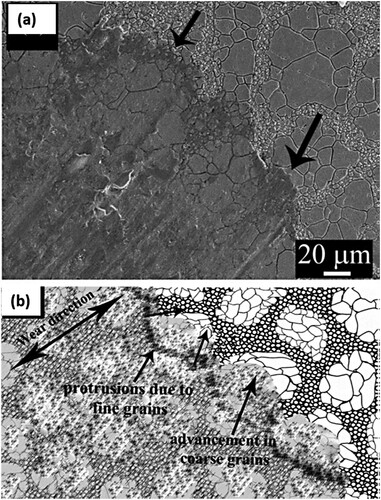
The mechanism of wear in harmonic structured stainless steel is shown in Figure . Figure (a) represents the SEM image of the scar after wear, whereas Figure (b) displays the wear mechanism through schematic of the worn-out surface. Due to the higher hardness, the fine grain region offered higher resistance to wear, leading to the formation of protrusions, and relatively more wear in the coarse-grained region. It appears that the relatively harder shell region and the protrusions suppress the removal of material up to a certain limit, followed by the removal of material in the form of debris beyond this limit and more abrasion.
Figure 31. (a) SEM micrograph of the wear scar after fretting wear, and (b) schematic showing mechanism of wear, in the harmonic structure stainless steel.
Apart from mechanical properties, the degradation of structural materials due to corrosion is also an important aspect to assess the service life of components. In general, the corrosion behavior is related to the electrochemical nature of the materials and their chemical response towards the service environment. However, the microstructure of the materials, such as grain size, grain size distribution, and presence of different phases, also affect the corrosion behavior of the materials to great extent. Generally, it is postulated that the grain refinement could lead to poor corrosion properties due to the presence of a higher amount of grain boundaries which are highly reactive sites in the materials. However, various studies on the effect of grain size on corrosion behavior have yielded contradictory results, i.e. both positive and negative effects of grain refinement on corrosion resistance [Citation80–83].
Apart from load-bearing structural applications, austenitic steels are also used in chemical processing equipment, beverages industries, dairy industry, and bio-implants due to their excellent corrosion resistance [Citation16,Citation84]. Since the harmonic structured austenitic steels consist of both fine-grained and coarse-grained regions in the microstructure, the corrosion behavior of the austenitic steels (304 L and 316 L grade) was also evaluated in view of their widespread applications in aforementioned engineering applications. The corrosion behavior was examined in 3.5% NaCl solution (electrochemical tests and salt fog tests), and Hanks simulated body fluid solution. It was observed that harmonic structured steels exhibited better corrosion resistance as compared to non-harmonic and conventional austenitic steels [Citation85,Citation86]. The highest corrosion resistance was attributed to its unique microstructure consisting of uniform distribution of the fine- and coarse-grained regions, higher fractions of grain boundaries, and negligible porosity. The fine-grained shell region of the harmonic structure was found to corrode more as compared to the coarse-grained core region, and the relatively higher rate of corrosion of the shell region was attributed to the presence of the larger amount of grain boundaries in this region. However, at the same time, the harmonic steel exhibited the higher pitting resistance as compared to the non-harmonic steel due to its peculiar microstructure due to the formation of extremely fine pits in the harmonic steels as compared to the larger pits formed in the non-harmonic and conventional steels. In general, the better passivation ability and the presence of a large fraction of passive α-FeOOH, due to continuous formation and destruction of the passive layer along the fine-grained sections leading to more uniform type corrosion mode, was found to be one of the important reasons for the better corrosion resistance of the harmonic structured steels as compared to non-harmonic austenitic steels.
11. Effect of thermo-mechanical treatment on the microstructure and properties
Varieties of processing steps such as mechanical plastic deformation, thermal, thermo-mechanical processing, or a combination of them, are required to prepare metallic components of useful shape such as plates, sheets, body panels, rods, wires, and any other complex shape. As a consequence, a wide range of microstructural features evolves in the products depending on the processing history and parameters, such as the nature of plastic deformation, processing temperature, time of heat treatment, and the sequence of the various steps. Therefore, the processing history has a significant effect on the microstructure and mechanical properties of the finished product. Therefore, the effect of thermomechanical processing (TMP), consisting of cold rolling followed by annealing, on the microstructure and mechanical properties of the Harmonic Structure designed materials was studied, wherein harmonic structured pure Ti (HS–Ti) was taken as model material [Citation87]. The thermomechanical processing of the sintered Homo-Ti and HS-Ti specimens involved cold rolling of the specimens from 10% to 30% thickness reduction at room temperature followed by their annealing at 873 K for 1.8 ks under argon atmosphere [Citation87].
It has been observed that the plastic deformation of heterogeneous HS-Ti is accompanied by localization of strain due to the formation and accumulation of dislocations in preferential areas of the Shell and Shell–Core interface region both at 10% as well as 30% degree of deformation. Further, the subsequent heat treatment of the plastically deformed HS-Ti exhibits the occurrence of peculiar preferential recrystallization localized in the Shell region of the HS-Ti specimens due to the aforementioned preferential strain localization in the Shell during plastic deformation. It has also been observed that an increasing degree of plastic deformation results in a gradual increase in the grain size and the volume fraction of the Shell region whereas no significant effect of degree of deformation can be observed on the grain size of the core. Based on the results, the mechanism of microstructural development in the TMP HS-Ti specimens is proposed, as depicted in the Figure . The development of preferentially recrystallized Shell can be explained through the accommodation of deformation gradients by the generation of Geometrically Necessary Dislocations (GNDs) to keep compatibility among neighboring grains [Citation26,Citation88]. Therefore, it can be expected that the heterogeneity of microstructure in the Shell–Core and gradient structured Shell induces a significant strain gradient at the Shell–Core interfaces and Shell, which results in the larger number of GNDs accumulation near the Shell–Core interface areas and inside the Shell [Citation89]. Consequently, as the degree of deformation due to thickness reduction by cold rolling increases, an enhanced pile-up, and multiplication of dislocations near the Core–Shell interface can be expected. Such a deformation behavior leads to the formation of a wider deformed region, which finally transforms to the broader recrystallized shell region after the annealing treatment. The Thermo-mechanically treated HS-Ti specimens exhibit considerably higher strength values and comparable ductility with respect to its Homo-Ti and as-sintered HS-Ti counterparts, wherein the yield strength and ultimate tensile strength also increase with increasing volume fraction of recrystallized shell region caused by an increasing degree of plastic deformation (Figure ).
Figure 32. The schematic diagram shows the development of the Shell structure from the as-sintered state to successive thermo-mechanically processed (TMP) states.
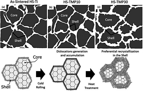
Figure 33. The nominal stress-strain curves of (a) Homo-Ti and (b) HS-Ti, respectively.
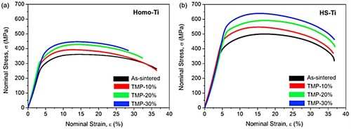
12. Future research directions
Wu and Zhu [Citation90] presented the perspectives in terms of mechanical properties and, more particularly, the synergy between mechanical strength and ductility of heterogeneous structures. In particular, it is theorized that a high density of interfaces is a necessary condition to induce back stress, a key for a better combination of mechanical properties. Thus, to enhance the strengthening due to the harmonic structure design as developed here, a strategy that introduces shape anisotropy into the structure could be a future development path. Such microstructures can be achieved in Laser Powder Bed Fusion (LPBF) technology. Figure shows an as-processed LPBF microstructure of a Ti-Nb-Zr (Ta, Mo) high entropy alloy. The significant variability of the development parameters in the LPBF could make it possible to generate a heterogeneous structure with both spacing between the domain interfaces large enough to allow an effective dislocation pile-up in the soft domains at least, and ideally in both soft and hard parts, but also with different grain size morphologies in the core. This is quite close to the lamellar structures [Citation90].
Figure 34. IPF and grain boundary map of structure of additively manufactured a heterogeneous Ti-Nb-Zr (Ta, Mo) high entropy alloy. (Courtesy Prof. G. Dirras).
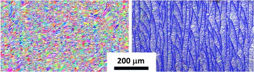
The aging population in our modern societies and the increased risk of bone diseases or bone accidents are constantly growing, and the development of long-lasting implantable osteosynthesis materials is a sustained drive to cater to the above health issue. Indeed, titanium and conventional titanium alloys are widely used in medical implants, since they offer a good combination of optimal strength as well as bio-compatibility. Nevertheless, these devices’ mechanical properties, including fatigue impact resistance, can be further improved based on incorporation of the harmonic structure design, as demonstrated in this review. It would be necessary to prove that the harmonic structure offers possibilities of chemical and biochemical functionalization at least equivalent to that of conventional alloys. Thus, a possible direction for future research should focus on the functionalization of bulk biomaterials (Ti alloys in this case) with the harmonic structure, such as a pure Ti parts with the harmonic structure, as shown in Figure . In reality, such studies have recently begun [Citation91]. However, their scope is still insufficient and needs sufficient drive.
Figure 35. A set of pure Ti bolt and nut with the harmonic structure.
13. Summary & conclusions
Although the harmonic structure material is a hetero-structure material, it deforms more uniformly than the conventional materials, resulting in high ductility and toughness along with high strength. This can be achieved by work hardening due to dislocation generation, accumulation, and movement in the nanoscale region and large uniform deformation as a result of suppression of deformation localization in the macroscale region. This attributes to the result of the superposition of nanoscale and macroscale microstructure contributing to the mechanical properties. In addition, stress concentration in shells can cause selective phase transformation and recrystallization even in small deformations. In the process of microstructure formation from nanocrystalline grains, not only grain size gradients but also constituent phase gradients due to elemental distribution are generated. In addition, the HS materials also demonstrate good wear and corrosion properties [Citation78,Citation88].
These unique phenomena create a synergy between nano- and macro-scale phenomena, and this is the goal of nano-engineering leading to the development of innovative mechanical properties, which are extremely important in practical applications. There are still many unknown phenomena between nano and macro scales, and critical and sustained effort in the elucidation of these unique phenomena would lead to new material innovations.
Recently, Shimokawa et al. [Citation92] have performed atomic and dislocation simulations on analysis models that render the three main characteristics of the HS materials: heterogeneous distribution of stress, core–shell interface, and shell network. They have investigated the mechanism of the excellent mechanical properties of the HS materials. It has been reported that the HS materials exhibit synergistic effects owing to the coexistence of Core and Shell regions, and this is caused by the heterogeneous evolution of lattice defects near the core–shell interface. Core regions having larger grains and lower strength plastically deform before the Shell regions having higher strength. The plastic deformation propagation from the core to shell regions is hindered by the core–shell interfaces because of the back stress induced by the transmitted dislocations in the shell. It increases the dislocation density of the core regions in contact with the interface, resulting in an increased strength and work-hardening rate in the core regions. The former contributes to the high strength in the harmonic structure materials, and the latter can suppress the plastic instability of the shell regions, resulting in higher ductility of the HS materials.
Supplemental Material
Download PDF (1.7 MB)Disclosure statement
No potential conflict of interest was reported by the author(s).
Additional information
Funding
References
- Wu XL, Jiang P, Chen L, et al. Extraordinary strain hardening by gradient structure. Proc Natl Acad Sci USA. 2014;11(20):7197–7201.
- Tsuji N, Ito Y, Saito Y, et al. Strength and ductility of ultrafine-grained aluminum and iron produced by ARB and annealing. Scripta Mater. 2002;47(12):893–899.
- Ma E, Zhu T. Towards strength–ductility synergy through the design of heterogeneous nanostructures in metals. Mater Today. 2017;20(6):323–331.
- Zhu Y, Ameyama K, Anderson PM, et al. Heterostructured materials: superior properties from hetero-zone interaction. Mat Res Lett. 2021;9:1–31.
- Wang YM, Chen M, Zhou F, et al. High tensile ductility in a nanostructured metal. Nature. 2002;419:912–915.
- Wu X, Yang M, Yuan F, et al. Heterogeneous lamella structure unites ultrafine-grain strength with coarse-grain ductility. PNAS. 2015;112:14501–14505.
- Yin Z, Yang X, Ma X, et al. Strength and ductility of gradient structured copper obtained by surface mechanical attrition treatment. Mater Des. 2016;105:89–95.
- Fischer FD, Reisner G, Werner E, et al. A new view on transformation induced plasticity (TRIP). Int J Plast. 2000;16:723–748.
- Cooman BCD, Estrin Y, Kim SK. Twinning-induced plasticity (TWIP) steels. Acta Mater. 2018;142:283–362.
- Sharma B, Dirras G, Ameyama K. Harmonic structure design: a strategy for outstanding mechanical properties in structural materials. Metals. 2020;10(12):1615.
- Vajpai SK, Ota M, Zhang Z, et al. Three-dimensionally gradient harmonic structure design: an integrated approach for high performance structural materials. Mater Res Lett. 2016;4:191–197.
- Vajpai SK, Sawangrat C, Yamaguchi O, et al. Effect of bimodal harmonic structure design on the deformation behaviour and mechanical properties of Co-Cr-Mo alloy. Mater Sci Eng C. 2016;58:1008–1015.
- Orlov D, Ameyama K. Critical assesment 37: harmonic-structure materials – idea, status and perspectives. Mater Sci Technol. 2020;36(5):517–526.
- Ota M, Vajpai SK, Imao R, et al. Application of high pressure Gas Jet mill process to fabricate high performance harmonic structure designed pure titanium. Mater Trans. 2015;56:154–159.
- Nagata M, Horikawa H, Kawabata M, et al. Effects of microstructure on mechanical properties of harmonic structure designed pure Ni. Mater Trans. 2019;60:1914–1920.
- Zhang Z, Vajpai SK, Orlov D, et al. Improvement of mechanical properties in SUS304L steel through the control of bimodal microstructure characteristics. Mater Sci Eng A. 2014;598:106–113.
- Vajpai SK, Ota M, Watanabe T, et al. The development of high performance Ti-6Al-4V alloy via a unique microstructural design with bimodal grain size distribution. Metal Mater Trans A. 2015;46A:903–914.
- Sharma B, Yagi K, Vajpai SK, et al. A novel bimodal milling (BiM) approach to achieve harmonic structured SUS316L with controlled microstructure and outstanding mechanical performance. Powder Technol. 2022;399:117188.
- Ameyama K, Kawabata M, Sharma B. The 29th international ocean and polar engineering conference, Honolulu, Hawaii, USA, June 2019: ISOPE-I-19-101.
- Kikuchi S, Mori T, Kubozono H, et al. Evaluation of near-threshold fatigue crack propagation in harmonic-structured CP titanium with a bimodal grain size distribution. Eng Fract Mech. 2017;181:77–86.
- Kikuchi S, Kubozono H, Nukui Y, et al. Statistical fatigue properties and small fatigue crack propagation in bimodal harmonic structured Ti-6Al-4V alloy under four-point bending. Mater Sci Eng A. 2018;711:29–36.
- Zhang Z, Ma H, Zheng R, et al. Fatigue behavior of a harmonic structure designed austenitic stainless steel under uniaxial stress loading. Mater Sci Eng A. 2017;707:287–294.
- Dirras G, Tingaud D, Ueda D, et al. Dynamic Hall-Petch versus grain-size gradient effects on the mechanical behavior under simple shear loading of β-titanium Ti-25Nb-25Zr alloys. Mater Lett. 2017;206:214–216.
- Dirras G, Ueda D, Hocini A, et al. Cyclic shear behavior of conventional and harmonic structure-designed Ti-25Nb-25Zr β-titanium alloy: back-stress hardening and twinning inhibition. Scripta Mater. 2017;138:44–47.
- Dirras G, Ota M, Tingaud D, et al. Microstructure evolution during direct impact loading of commercial purity α-titanium with harmonic structure design. Matér Tech. 2015;103/311:1–9.
- Yang M, Pan Y, Yuan F, et al. Back stress strengthening and strain hardening in gradient structure. Mater Res Lett. 2016;4:145–151.
- Li G, Liu M, Lyu S, et al. Simultaneously enhanced strength and strain hardening capacity in FeMnCoCr high-entropy alloy via harmonic structure design. Scripta Mater. 2021;191:196–201.
- Orlov D, Kulagin R, Beygelzimer Y. Strain partitioning and back-stress evaluation in harmonic-structure materials. Mater Lett. 2020;275:128126.
- Orlov D, Zhou J, Hall S, et al. Advantages of architectured harmonic structure in structural performance. IOP Conf Ser: Mater Sci Eng. 2019;580(012019):265–272.
- Yu H, Watanabe I, Ameyama K. Deformation behavior analysis of harmonic structure materials by multi-scale finite element analysis. Adv Mater Res. 2015;1088:853–857.
- Shokry A, Ahadi A, Ståhle P, et al. Improvement of structural efficiency in metals by the control of topological arrangements in ultrafine and coarse grains. Sci Rep. 2021;11(1):17445.
- Liu J, Li J, Dirras G, et al. A three-dimensional multi-scale polycrystalline plasticity model coupled with damage for pure Ti with harmonic structure design. Int J Plast. 2018;100:192–207.
- Wang X, Cazes F, Li J, et al. A 3D crystal plasticity model of monotonic and cyclic simple shear deformation for commercial-purity polycrystalline Ti with a harmonic structure. Mech Mater. 2019;128:117–128.
- Wang X, Li J, Cazes F, et al. A three-dimensional microstructure-based crystal plasticity model for coarse-grained and harmonic-structured Ti–6Al–4V under monotonic and cyclic shear loading. Acta Mech. 2020;231:4991–5005.
- Wang X, Li J, Cazes F, et al. Numerical modeling on strengthening mechanisms of the harmonic structured design on CP-Ti and Ti–6Al–4V. Int J Plast. 2020;133:102793.
- Meŕic L, Poubanne P, Cailletaud G. Single crystal modeling for structural calculations: part 1—model presentation. J Eng Mater Technol. 1991;113:162–170.
- Cailletaud G. Une Approche Micromécanique Phénoménologique du comportement Inélastique des Métaux, Thèse d’état, Université Pierre et Marie Curie, Paris 6, 1987.
- Pilvin P. Approches multi-échelles pour la prévision du comportement anélastique des métaux. PhD thesis, Université Pierre et Marie Curie, Paris 6, 1990.
- Cailletaud G, Pilvin P. Utilisation de modéles polycristallins pour le calcul par éléments finis. Rev Eur Eléments Finis. 1994;3:515–541.
- Vajpai SK, Yu H, Ota M, et al. Three-dimensionally gradient and periodic harmonic structure for high performance advanced structural materials. Mater Trans. 2016;57:1424–1432.
- Goh CH, Neu RW, McDowell DL. Crystallographic plasticity in fretting of Ti-6Al-4V. Int J Plast. 2003;19:1627–1650.
- Mayeur JR. M.S. Thesis, Georgia Institute of Technology, Atlanta (2004).
- Mompiou F, Tingaud D, Chang Y, et al. Conventional vs harmonic-structured β-Ti-25Nb-25Zr alloys: a comparative study of deformation mechanisms. Acta Mater. 2018;161:420–430.
- Castany P, Pettinari-Sturmel F, Crestou J, et al. Experimental study of dislocation mobility in a Ti–6Al–4V alloy. Acta Materialia. 2007;55:6284–6291.
- Neeraj T, Mills MJ. Short-range order (SRO) and its effect on the primary creep behavior of a Ti–6wt.%Al alloy. Mater Sci Eng A. 2001;319-321:415–419.
- Hocini A. Comparative study of the mechanical behavior and deformation mechanisms under simple and cyclic shear of titanium alloys produced by powder metallurgy: harmonic structures versus conventional alloys, PhD thesis, University Sorbonne Paris North, 2017.
- Mompiou F, Caillard D, Legros M, et al. In situ TEM observations of reverse dislocation motion upon unloading in tensile-deformed UFG aluminium. Acta Mater. 2012;60:3402–3414.
- Caillard D. A TEM in situ study of alloying effects in iron. II—solid solution hardening caused by high concentrations of Si and Cr. Acta Mate. 2013;61:2808–2827.
- Caillard D. A TEM in situ study of the softening of tungsten by rhenium. Acta Mater. 2020;194:249–256.
- Couque H. The use of the direct impact Hopkinson pressure bar technique to describe thermally activated and viscous regimes of metallic materials. Philos Trans R Soc A. 2014;372:20130218.
- Zerilli FJ, Armstrong RW. The effect of dislocation drag on the stress-strain behavior of F.C.C. metals. Acta Metall Mater. 1992;40:1803–1808.
- Recht RF. Catastrophic thermoplastic shear. J Appl Mech. 1964;31:186–193.
- Li Z, Zhao S, Alotaibi SM, et al. Adiabatic shear localization in the CrMnFeCoNi high-entropy alloy. Acta Mater. 2018;151:424–431.
- Wang ZG, Rittel G. Thermomechanical aspects of adiabatic shear failure of AM50 and Ti-6Al-4V alloys. Mech Mater. 2008;40(8):629–635.
- Dirras G, Couque H, Gubicza J, et al. Fine-grained nickel deformed by direct impact at different velocities: microstructure and mechanical properties. Mater Sci Eng A. 2010;527:4128–4135.
- Rittel D. A different viewpoint on adiabatic shear localization. J Phys D Appl Phys; 42(21):214009.
- Wang B, Yao XR, Liu L, et al. Mechanical properties and microstructure in a fine grained Ti-5Al-5Mo-5V-1Cr-1Fe titanium alloy deformed at a high strain rate. Mater Sci Eng A. 2018;736:202–208.
- Hines JA, Vecchio KS. Recrystallization kinetics within adiabatic shear bands. Acta Mater. 1997;45:635–649.
- Li Z, Wang B, Zhao S, et al. Dynamic deformation and failure of ultrafine-grained titanium. Acta Mater. 2017;125:210–218.
- Wang B, Sun J, Wang X, et al. Adiabatic shear localization in a near-beta Ti–5Al–5Mo–5V–1Cr–1Fe alloy. Mater Sci Eng A. 2015;639:526–533.
- Nesterenko V, Meyers M, LaSalvia JC, et al. Shear localization and recrystallization in high-strain, high-strain-rate deformation of tantalum. Mater Sci Eng A. 1997;229:23–41.
- Nukui Y, Kubozono H, Kikuchi S, et al. Fractographic analysis of fatigue crack initiation and propagation in CP titanium with a bimodal harmonic structure. Mater Sci Eng A. 2018;716:228–234.
- Osaki K, Kikuchi S, Nakai Y, et al. The effects of thermo-mechanical processing on fatigue crack propagation in commercially pure titanium with a harmonic structure. Mater Sci Eng A. 2020;773:138892.
- Nakai Y, Kikuchi S, Osaki K, et al. Effects of rolling reduction and direction on fatigue crack propagation in commercially pure titanium with harmonic structure. Int J Fatigue. 2021;143:106018.
- Kikuchi S, Imai T, Kubozono H, et al. Evaluation of near-threshold fatigue crack propagation in Ti-6Al-4V alloy with harmonic structure created by mechanical milling and spark plasma sintering. Frat Integrita Strutt. 2015;34:261–270.
- Kikuchi S, Takemura K, Hayami Y, et al. Evaluation of the 4-points bending fatigue properties of Ti-6Al-4V alloy with harmonic structure created by mechanical milling and spark plasma sintering. J Soc Mat Sci. 2015;64:880–886.
- Kikuchi S, Imai T, Kubozono H, et al. Effect of harmonic structure design with bimodal grain size distribution on near-threshold fatigue crack propagation in Ti-6Al-4V alloy. Int J Fatigue. 2016;92:616–622.
- Kikuchi S, Hayami Y, Ishiguri T, et al. Effect of bimodal grain size distribution on fatigue properties of Ti-6Al-4V alloy with harmonic structure under four-point bending. Mater Sci Eng A. 2017;687:269–275.
- Guennec B, Ishiguri T, Kawabata M, et al. Investigation on the durability of Ti-6Al-4V alloy designed in a harmonic structure via powder metallurgy: fatigue behavior and specimen size parameter issue. Metals. 2020;10:636.
- Kikuchi S, Nakatsuka Y, Nakai Y, et al. Evaluation of fatigue properties under four-point bending and fatigue crack propagation in austenitic stainless steel with a bimodal harmonic structure. Frat Integrita Strutt. 2019;48:545–553.
- Kikuchi S, Nukui Y, Nakatsuka Y, et al. Effect of bimodal harmonic structure on fatigue properties of austenitic stainless steel under axial loading. Int J Fatigue. 2019;127:222–228.
- Kikuchi S, Ueno A, Akebono H. Combined effects of low temperature nitriding and cold rolling on fatigue properties of commercially pure titanium. Int J Fatigue. 2020;139:105772.
- Rabinowicz E. Friction and wear of materials. 2nd ed New York: Wiley-Interscience; 1995.
- Rai PK, Shekhar S, Mondal K. Effect of grain size gradients on the fretting wear of a specially processed low carbon steel against AISI E52100 bearing steel. Wear. 2018;412-413:1–13.
- Zhang YS, Han Z, Wang K, et al. Friction and wear behaviors of nanocrystalline surface layer of pure copper. Wear. 2006;260:942–948.
- El-Raghy T, Blau P, Barsoum MW. Effect of grain size on friction and wear behavior of Ti3Si3C. Wear. 2000;238:125–130.
- Wang XY, Li DY. Mechanical, electrochemical and tribological properties of nanocrystalline surface of 304 stainless steel. Wear. 2003;255:836–845.
- Rai PK, Shekhar S, Nakatani M, et al. Wear behavior of harmonic structured 304L stainless steel. J Mater Eng Perform. 2017;26:2608–2618.
- Rai PK, Shekhar S, Yagi K, et al. Fretting wear mechanism for harmonic, non-harmonic and conventional 316L stainless steels. Wear. 2019;424-425:23–32.
- Mahesh BV, Singh Raman RK. Role of nanostructure in electrochemical corrosion and high temperature oxidation: a review. Metall Mater Trans A. 2014;45:5799–5822.
- Ralston KD, Birbilis N. Effect of grain size on corrosion: a review. Corrosion. 2010;66:075005-5013.
- Ralston KD, Fabijanic D, Birbilis N. Effect of grain size on corrosion of high purity aluminium. Electrochimica Acta. 2011;56:1729–1736.
- Oguzie EE, Li Y, Wang FH. Effect of surface nanocrystallization on corrosion and corrosion inhibition of low carbon steel: synergistic effect of methionine and iodide ion. Electrochimica Acta. 2007;52:6988–6996.
- Xavior MA, Adithan M. Determining the influence of cutting fluids on tool wear and surface roughness during turning of AISI 304 austenitic stainless steel. J Mater Process Technol. 2009;209:900–909.
- Rai P, Shekhar S, Nakatani M, et al. Effect of harmonic microstructure on the corrosion behavior of SUS304L austenitic stainless steel. Metall Mater Trans A. 2016;47:6259–6269.
- Rai PK, Shekhar S, Yagi K, et al. Corrosion behavior of harmonic structured 316L stainless steel in 3.5% NaCl and simulated body fluid solution. J Mater Eng Perfor. 2019;28:7554–7564.
- Sharma B, Miyakoshi M, Vajpai SK, et al. Extra-strengthening in a harmonic structure designed pure titanium due to preferential recrystallization phenomenon through thermomechanical treatment. Mater Sci Eng A. 2020;797:140227.
- Demir E, Raabe D, Zaafarani N, et al. Investigation of the indentation size effect through the measurement of the geometrically necessary dislocations beneath small indents of different depths using EBSD tomography. Acta Mater. 2009;57:559–569.
- Park HK, Ameyama K, Yoo J, et al. Additional hardening in harmonic structured materials by strain partitioning and back. Mater Res Lett. 2018;6:261–267.
- Wu X, Zhu Y. Heterogeneous materials: a new class of materials with unprecedented mechanical properties. Mater Res Lett. 2017;5:527–532.
- Amokrane G, Hocini A, Ameyama K, et al. Functionalization of new biocompatible titanium alloys with harmonic structure design by UV irradiation. IRBM. 2017;4:190–197.
- Shimokawa T, Hasegawa T, Kiyota K, et al. Heterogeneous evolution of lattice defects leading to high strength and high ductility in harmonic structure materials through atomic and dislocation simulations. Acta Mater. 2022;226:117679.