
Abstract
Cold spray (CS) has emerged as a representative of solid-state additive manufacturing (AM) via supersonic impact. It enables a high deposition rate of solid-state microparticles. Delamination, however, tends to occur when depositing too thick; this remains to be conquered. Here, a CS-like process, warm spray (WS), was presented. Interestingly, it was found that the appropriate increase in particle temperature can effectively reduce the residual stress amplitude, relieving the concentrated tensile stress and safeguarding the additively manufactured components from interfacial delamination even when depositing too thick. The key role of temperature on delamination was identified in solid-state AM via supersonic impact.
GRAPHICAL ABSTRACT
IMPACT STATEMENT
It makes a clear understanding of the delamination issue in solid-state AM via supersonic impact, providing scientific guidance for technological/equipment upgrading and safeguarding the structural integrity of complex, large-size components.
1. Introduction
Additive manufacturing (AM) has been under rapid development owing to the great flexibility for personalized, lightweight, and complex designs of end-use products [Citation1,Citation2]. Over the past decades, various fusion-based AM processes, using laser [Citation3], arc [Citation4], or electron beam [Citation5] as heat sources for melting-solidification of metals to form deposits, have been extensively researched as mainstream. Adequate melting of metals ensures metallurgical bonding among deposited layers, whereas their rapid solidification is prone to bring problems with high thermal stress [Citation6], grain growth [Citation7], phase transformation [Citation8], and chemical degradation [Citation9]. DebRoy et al. [Citation10] reviewed AM of metallic components, highlighting the mainstream status of fusion-based AM processes while specifying the above problems to be solved. The advent of solid-state AM processes via supersonic impact, represented by cold spray (CS), signals a new direction. The formation of deposits relies on supersonic impact-induced extreme deformation rather than metal melting; hence, solidification-related problems can be minimized. Moreover, the nature of supersonic impact gives the benefits of high deposition rate and efficiency [Citation11,Citation12], making them of great interest to the scientific and industrial communities.
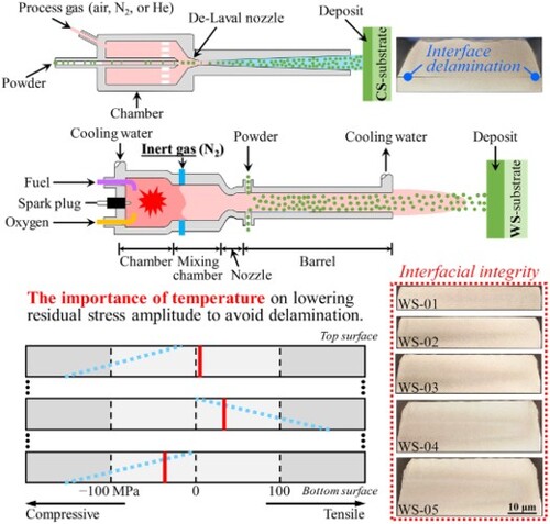
CS is currently the most representative solid-state AM process via supersonic impact, which has been written into the ASTM F2792-12A standard [Citation13]. During CS, the heated and pressurized process gas (generally air, N2, or He) passes through the de-Laval nozzle to create a near-room temperature supersonic flow to accelerate microparticles to supersonic speeds (Figure (a)). This process is similar to shot peening and tends to induce compressive residual stresses in favor of structural integrity. Moreover, it was recognized as having no deposition thickness limitation due to the lack of thermal stress (near-room in-process temperature). In practice, however, delamination frequently occurs for thick deposits [Citation14–19], compromising component integrity and restricting the widespread application of CS as AM process. Vargas-Uscategui et al. [Citation15] explicitly displayed the delamination issue of thick pure Ti deposits additively manufactured by CS. Currently, this issue might be mitigated by optimizing the CS parameters, but the underlying cause remains unclear. Warm Spray (WS) is a CS-like process that utilizes the combustion gas produced by reacting fuel with oxygen as a supersonic flow and mixes inert gas (generally N2) to control the temperature (Figure (b)). It gives microparticles not only high-impact velocities like CS but also high temperatures below the melting point, which is more friendly to hard-to-deform materials. More interestingly, delamination rarely occurs in WS.
Figure 1. Schematic illustrating the differences between (a) cold spray and (b) warm spray systems [Citation20].
![Figure 1. Schematic illustrating the differences between (a) cold spray and (b) warm spray systems [Citation20].](/cms/asset/cc877dc6-60bc-4f3d-9e16-93e2a68b3723/tmrl_a_2227221_f0001_oc.jpg)
2. Materials and methods
Ni and its alloys are versatile and exhibit excellent performance in high-temperature and corrosive environments. It is of great significance to advance their AM for energy conservation and sustainability. Usually, common and well-known materials are preferred to avoid extraordinary phenomena caused by complex compositions. Hence, pure Ni was chosen as the target material in this study. Gas-atomized pure Ni microparticles with good sphericity (AMPERIT® 176.001, Höganäs Germany GmbH, Germany) were used for solid-state deposition, and pure Ni sheets (Kiguchi Technics Inc., Japan) cut to the 100 mm × 50 mm × 5 mm size were heat-treated and sandblasted as substrates. Pure Ni deposits of different thicknesses were additively manufactured by WS. For comparison, thick pure Ni deposits were also made by CS. The average impact velocities of microparticles during CS and WS were set to ∼700 m/s, measured by the particle image velocimetry method. Only during WS, the average temperature of microparticles was governed by N2 to ∼1000°C, while the substrate temperature was maintained at ∼300 °C by a temperature control fixture. In general, geometric distortion correlates closely with residual stresses. A portable X-ray diffraction (XRD) analyzer (μ-X360s, Pulstec Industrial Co.,Ltd., Japan) was employed to measure the surface residual stresses of deposits based on the cosα approach. The internal residual stresses were mapped by the contour method in three steps: (1) plane of interest cut with wire electrical discharge machining (AG360L, Sodick Co.,Ltd., Japan); (2) deformed contours of cut surfaces measured with wide-area 3D measurement system (VR-5000, KEYENCE Corp., USA); and (3) residual stress reproduced by an elastic finite element program JWRIAN developed by authors [Citation21–23].
3. Results and discussion
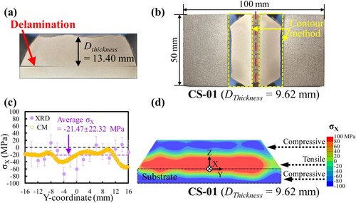
Figure shows the thick pure Ni deposits made by CS. It is evident that the tendency to delamination increases with increasing deposition thickness. Visible delamination was noticed at the deposit-substrate interface when the deposition thickness reached 13.40 mm (Figure (a)). For a thinner deposit, the interfacial integrity suggests that delamination is driven primarily by in-process stress release. To clarify, a residual stress analysis was performed for a non-delaminated deposit with a thickness of 9.62 mm (slightly less than 13.40 mm, Figure (b)). The insets in Figure (b) indicate the symmetrical cutting surfaces implemented by the contour method, with the cutting position marked by the red dash-dotted line. The results of both XRD and contour methods show that compressive residual stresses prevail on the deposit surface and fluctuate with position (Figure (c)). This is a typical feature of CS residual stresses without further details here. It is worth noting that the cross-sectional residual stress mapping through the contour method (Figure (d)). From top to bottom, the distribution pattern of residual stresses is compressive-tensile-compressive. High compressive residual stresses over 100 MPa exist close to the top surface, attributed to the peening effect accumulation of microparticles. The greater the deposition thickness, the higher the compressive residual stresses [Citation16,Citation24,Citation25]. Compressive residual stress is beneficial to the mechanical properties and service reliability of components. Nevertheless, the residual stresses are balanced in individual components. High compressive stresses concentrated near the top surface can lead to high tensile stresses concentrated in the interior shown in Figure (d), driving delamination. As a result, lowering the residual stress amplitude is essential to avoid delamination.
Figure 2. Delamination tends to occur when depositing (a) too thick pure Ni (Dthickness = 13.40 mm) via cold spray. Residual stress analysis for a cold-sprayed pure Ni deposit without delamination (CS-01) showing high residual stress amplitude dependent on delamination: (b) specimen photograph; (c) surface residual stresses obtained by the XRD and contour methods; (d) cross-sectional residual stress mapping through the contour method. CM refers to the contour method.
The pure Ni deposits of different thicknesses were additively manufactured by WS, as shown in Figure . The deposition thicknesses are 3.15 mm (Figure (a)), 6.06 mm (Figure (b)), 8.75 mm (Figure (c)), 12.83 mm (Figure (d)), and 15.05 mm (Figure (e)) in sequence. Symmetrical cross-sections obtained by cutting along red dash-dotted lines are presented as insets. As we all know [Citation26–28], the deposition inclination is usually noticeable in the thick deposits by CS owing to inadequate deformation of peripheral microparticles (e.g. Figure (a and b)). Compared to CS, WS tends to form thicker deposits with less inclination. The major difference between CS and WS in this study is the temperature. Correspondingly, the above comparison is a side-by-side reflection of the role of temperature in promoting particle deformation as well as interfacial bonding. What is more, no delamination was detected regardless of the deposition thickness (even exceeding 13.40 mm), indicating the superiority of WS in the AM of thick components. Likewise, the WS residual stresses were evaluated by a combination of XRD and contour methods. The measurement positions of the XRD method and the subsequent cutting position implemented by the contour method are identical and marked with red dash-dotted lines.
Figure 3. Specimen photographs showing no delamination of warm-sprayed pure Ni deposits with increasing thickness: (a) WS-01; (b) WS-02; (c) WS-03; (d) WS-04; (e) WS-05. Cutting positions of contour method implementation are marked with red dash-dotted lines.
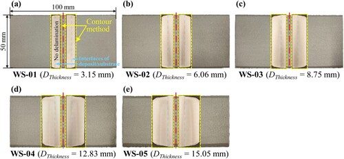
Figure (a) displays the residual stresses on the deposit surfaces of different thicknesses measured by the XRD and contour methods. The surface residual stresses fluctuate around zero and are less than those in CS (Figure (c)). This is because the microparticles in WS have higher temperatures, which relieves the compressive stresses caused by the peening effect. As the deposition thickness increases, there is a tendency for the surface residual stress to shift from compressive to tensile due to the enhanced temperature effect. Residual stresses were measured over the entire surface, and the conclusion is consistent. Incidentally, the results obtained by the two methods agree well to support the validity of the contour method.
Figure 4. Residual stress analysis for warm-sprayed pure Ni deposits with increasing thickness in Figure showing the critical role of temperature in lowering residual stress amplitude to avoid delamination: (a) surface residual stresses obtained by the XRD and contour methods; (b–f) cross-sectional residual stress mapping through the contour method.
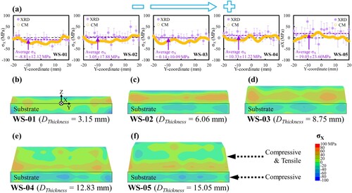
More importantly, the cross-sectional residual stress distributions in the deposits of different thicknesses were mapped by the contour method, as shown in Figure (b–f). Similar to CS, the distribution pattern of residual stresses from top to bottom is compressive/tensile-compressive. Unlike CS, the residual stress amplitude does not increase with increasing deposition thickness. The low compressive/tensile residual stresses exist near the top surface and are attributed to the compromise between the peening and temperature effects. Towards the interior, the internal heat of deposits was continuously accumulated (maintained at ∼300 °C), and tensile residual stresses were ubiquitous. The temperature of deposits was maintained at a low level (∼300 °C) during WS, so the induced tensile residual stresses are low. The sum of residual stresses is zero. As a result, there are compressive residual stresses near the bottom surface of deposits. Regardless of the deposition thickness, the residual stress amplitude does not exceed 50 MPa. The deposit-substrate interface is often the weakest bonding position in the entire deposit [Citation14–16,Citation29,Citation30]. The low residual stresses at this position provide support for component integrity. In other words, this finding further supports that reducing the residual stress amplitude is the key to avoiding delamination. Meanwhile, it is direct evidence of the critical role of temperature on delamination in solid-state AM via supersonic impact.
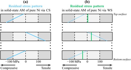
Hereafter, Figure schematizes the pattern differences of residual stress distributions in solid-state AM of pure Ni via CS and WS. Emphasis is placed on thick deposits. The residual stress distribution pattern of thick pure Ni deposits fabricated by CS is generalized in Figure (a). It is compressive-tensile-compressive from top to bottom. High compressive residual stresses near the top surface (caused by the peening effect accumulation in thick deposits) can effectively retard crack initiation/propagation and, thus, significantly improve fatigue performance. Nonetheless, the high compressive residual stresses mean high tensile residual stresses in the interior, especially at the deposit-substrate interface, triggering delamination. WS adds the significant influence of temperature on the basis of CS, which transforms the residual stress distribution pattern from Figure (a and b), as follows:
Near-zero low tensile residual stresses are predominant near the top surface owing to the compromise between the peening and temperature effects (∼1000 °C of particle temperature);
Internal tensile residual stresses are generated by heat accumulation, and the temperature is maintained at a low level (∼300 °C), resulting in low tensile residual stresses, which is the key to avoiding delamination;
Due to stress balance, there are low levels of compressive residual stresses near the bottom surface.
Figure 5. Schematics of the distribution pattern differences of residual stresses in solid-state additive manufacturing of pure Ni via (a) cold spray and (b) warm spray, illustrating the importance of temperature on delamination.
4. Conclusions
In summary, a distinct comparison of CS versus WS was given, identifying the key role of temperature on delamination in solid-state AM via supersonic impact. This work leads to new insights into the delamination issue. High compressive residual stresses on the surface favor improved fatigue performance. Due to stress balance, however, high tensile residual stresses inside can result in interface delamination. Temperature is conventionally regarded as an adverse factor. Nevertheless, it is found that the appropriate in-process temperature can effectively relieve the high compressive residual stresses caused by the accumulation of peening effects and keep the stress amplitude at a low level, which contributes to the structural integrity of large-size components subjected to solid-state AM via supersonic impact. This finding is guiding the AM of thick Inconel 718 deposits. In the future, the temperature-stress-delamination relationship will be quantified based on a multi-scale modeling strategy to provide scientific guidance for safeguarding the structural integrity of complex, large-size components.
Disclosure statement
No potential conflict of interest was reported by the author(s).
Additional information
Funding
References
- Herzog D, Seyda V, Wycisk E, et al. Additive manufacturing of metals. Acta Mater. 2016;117:371–392.
- Ngo TD, Kashani A, Imbalzano G, et al. Additive manufacturing (3D printing): a review of materials, methods, applications and challenges. Compos Pt B-Eng. 2018;143:172–196.
- Tan C, Weng F, Sui S, et al. Progress and perspectives in laser additive manufacturing of key aeroengine materials. Int J Mach Tools Manuf. 2021;170:103804.
- Cunningham CR, Flynn JM, Shokrani A, et al. Invited review article: strategies and processes for high quality wire arc additive manufacturing. Addit Manuf. 2018;22:672–686.
- Körner C. Additive manufacturing of metallic components by selective electron beam melting—a review. Int Mater Rev. 2016;61:361–377.
- Luo Z, Zhao Y. A survey of finite element analysis of temperature and thermal stress fields in powder bed fusion additive manufacturing. Addit Manuf. 2018;21:318–332.
- Yang M, Wang L, Yan W. Phase-field modeling of grain evolutions in additive manufacturing from nucleation, growth, to coarsening. npj Comput Mater. 2021;7:1–2.
- Guo Q, Qu M, Chuang CA, et al. Phase transformation dynamics guided alloy development for additive manufacturing. Addit Manuf. 2022;59:103068.
- Powell D, Rennie AE, Geekie L, et al. Understanding powder degradation in metal additive manufacturing to allow the upcycling of recycled powders. J Clean Prod. 2020;268:122077.
- DebRoy T, Wei HL, Zuback JS, et al. Additive manufacturing of metallic components–process, structure and properties. Prog Mater Sci. 2018;92:112–224.
- Luo XT, Li CX, Shang FL, et al. High velocity impact induced microstructure evolution during deposition of cold spray coatings: a review. Surf Coat Technol. 2014;254:11–20.
- Bagherifard S, Kondas J, Monti S, et al. Tailoring cold spray additive manufacturing of steel 316 L for static and cyclic load-bearing applications. Mater Des. 2021;203:109575.
- Flynn JM, Shokrani A, Newman ST, et al. Hybrid additive and subtractive machine tools–research and industrial developments. Int J Mach Tools Manuf. 2016;101:79–101.
- Phuong V, Stephen Y, Wilson W. Is cold spray additive manufacturing? Conference of Metallurgists (COM) 2020, August 24–27, 2020, Toronto, Canada, 2020.
- Vargas-Uscategui A, King PC, Styles MJ, et al. Residual stresses in cold spray additively manufactured hollow titanium cylinders. J Therm Spray Technol. 2020;29:1508–1524.
- Singh R, Schruefer S, Wilson S, et al. Influence of coating thickness on residual stress and adhesion-strength of cold-sprayed Inconel 718 coatings. Surf Coat Technol. 2018;350:64–73.
- White BC, Story WA, Brewer LN, et al. Fracture mechanics methods for evaluating the adhesion of cold spray deposits. Eng Fract Mech. 2019;205:57–69.
- Vargas-Uscategui A, King PC, Yang S, et al. Toolpath planning for cold spray additively manufactured titanium walls and corners: effect on geometry and porosity. J Mater Process Technol. 2021;298:117272.
- Lett S, Quet A, Hémery S, et al. Residual stresses development during cold spraying of Ti-6Al-4V combined with in situ shot peening. J Therm Spray Technol. 2022;32:1018–1032.
- Kuroda S, Kawakita J, Watanabe M, et al. 7 – Current status and future prospects of warm spray technology. In: Espallargas N, editor. Future development of thermal spray coatings: types, designs, manufacture and applications. Cambridge: Elsevier; 2015. p. 163–206.
- Wang Q, Luo X, Tsutsumi S, et al. Measurement and analysis of cold spray residual stress using arbitrary Lagrangian–Eulerian method. Addit Manuf. 2020;35:101296.
- Huang W, Wang Q, Ma N, et al. Distribution characteristics of residual stresses in typical wall and pipe components built by wire arc additive manufacturing. J Manuf Process. 2022;82:434–447.
- Muhammad NA, Geng P, Wu C, et al. Unravelling the ultrasonic effect on residual stress and microstructure in dissimilar ultrasonic-assisted friction stir welding of Al/Mg alloys. Int J Mach Tools Manuf. 2023;186:104004.
- Boruah D, Ahmad B, Lee TL, et al. Evaluation of residual stresses induced by cold spraying of Ti-6Al-4V on Ti-6Al-4V substrates. Surf Coat Technol. 2019;374:591–602.
- Marzbanrad B, Toyserkani E, Jahed H. Customization of residual stress induced in cold spray printing. J Mater Process Technol. 2021;289:116928.
- Li Y, Wei Y, Luo X, et al. Correlating particle impact condition with microstructure and properties of the cold-sprayed metallic deposits. J Mater Sci Technol. 2020;40:185–195.
- Pattison J, Celotto S, Morgan R, et al. Cold gas dynamic manufacturing: a non-thermal approach to freeform fabrication. Int J Mach Tools Manuf. 2007;47:627–634.
- Wu H, Xie X, Liu M, et al. Stable layer-building strategy to enhance cold-spray-based additive manufacturing. Addit Manuf. 2020;35:101356.
- Wu H, Xie X, Liu S, et al. Bonding behavior of Bi-metal-deposits produced by hybrid cold spray additive manufacturing. J Mater Process Technol. 2022;299:117375.
- Tan AW, Sun W, Phang YP, et al. Effects of traverse scanning speed of spray nozzle on the microstructure and mechanical properties of cold-sprayed Ti6Al4 V coatings. J Therm Spray Technol. 2017;26:1484–1497.