
 ?Mathematical formulae have been encoded as MathML and are displayed in this HTML version using MathJax in order to improve their display. Uncheck the box to turn MathJax off. This feature requires Javascript. Click on a formula to zoom.
Abstract
Severe plastic deformations under high pressure are used to produce nanostructured materials but were studied ex-situ. Rough diamond anvils are introduced to reach maximum friction equal to yield strength in shear and the first in-situ study of the evolution of the pressure-dependent yield strength and radial distribution of nanostructural parameters are performed for severely pre-deformed Zr. ω-Zr behaves like perfectly plastic, isotropic, and strain-path-independent and reaches steady values of the crystallite size and dislocation density, which are pressure-, strain- and strain-path-independent. However, steady states for α-Zr obtained with smooth and rough anvils are different, causing major challenge in plasticity theory.
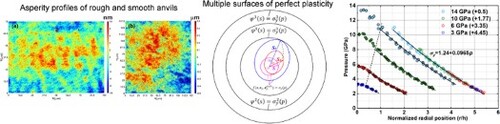
GRAPHICAL ABSTRACT
IMPACT STATEMENT
In-situ study of severe plastic deformation of ω-Zr with rough diamond anvils revealed that pressure-dependent yield strength, crystallite size, and dislocation density are getting steady and plastic strain- and strain-path-independent.
1. Introduction
Processes involving severe plastic deformations (SPD) under high pressure are common in producing nanostructured materials [Citation1–8], in functional materials experiencing extreme stresses under contact friction, collision, and penetration, and in geophysics [Citation9,Citation10]. The effects of SPD under high pressure on microstructure evolution are mostly studied with high-pressure torsion (HPT) with metallic or ceramic anvils [Citation1–4]. Stationary states after SPD in terms of torque, hardness, grain size, and dislocation density are well-known in literature, particularly after HPT, along with many cases where they were not observed [Citation1–8, Citation11]. However, all these results were not observed in-situ but obtained postmortem after pressure release and further treatment during sample preparation for mechanical and structural studies (see supplementary material). The direct effect of pressure and the combined effect of pressure and plastic straining on the yield strength, crystallite size, and dislocation density were not determined. This is very important because, as one will see, the yield strength of the ω-Zr doubles at ∼13 GPa, but hardness and, consequently, yield strength after pressure release are independent of the pressure at HPT [Citation12]. The only paper [Citation13] studies in situ the microstructure evolution in Ni and amorphization and a reverse martensitic transformation in NiTi during HPT in a single peripheral region (see details in supplementary material). During pressure release after HPT of Ni, crystallite size increases, and dislocation density decreases by a factor of 2 [Citation13]. Similar results were obtained for Zr under hydrostatic loading [Citation14].
Robust method for measurement of the yield strength in compression under high pressure p is lacking. The main difficulty in studying plasticity, structural changes, and contact friction is that they depend on five components of the plastic strain tensor
and its entire path
, making an unspecifiable number of combinations of independent parameters. The yield surface in the 5D deviatoric stress
space
depends on
,
, and
, demonstrating strain hardening/softening and strain-induced anisotropy. This complexity makes it impossible to determine the complete evolution of the yield surface, even at small strains and ambient condition. For measurement of yield strength at high pressure, all methods [Citation15–17] treat the yield surface as
, i.e. like for perfectly plastic material (for which the yield surface is independent of
and
, i.e. is fixed in the 5D stress space), and dependence on
and
is neglected and merged in pressure, which causes large error. One of the methods to determine the yield strength in shear
in diamond anvil cell (DAC) is based on applying the simplified equilibrium equation
assuming the anvil-sample contact friction stress
[Citation16–18] (see supplement). Here,
is the pressure averaged over the sample current thickness h. However, recent experiments [Citation15, Citation19] show that
. Coupled simulations and experiments demonstrate that
only in a small region, even above 100 GPa [Citation20]. Rough diamond anvil (rough-DA), whose culet is roughly polished to increase friction (Figure ), is introduced. It is demonstrated that maximum friction
is reached for rough-DA, which allowed us to robustly determine
and plastic friction.
Figure 1. Surface asperity profile of a smooth-DA and a rough-DA. (a) Traditional smooth-DA with an asperity profile range [−10 nm; 10 nm] and (b) rough-DA with range [−500 nm; 500 nm].
![Figure 1. Surface asperity profile of a smooth-DA and a rough-DA. (a) Traditional smooth-DA with an asperity profile range [−10 nm; 10 nm] and (b) rough-DA with range [−500 nm; 500 nm].](/cms/asset/785598cd-345d-42d2-8ec9-77353cee2a57/tmrl_a_2231983_f0001_oc.jpg)
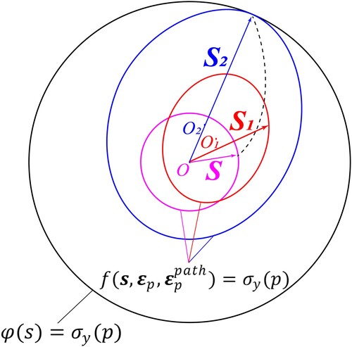
It was hypothesized in [Citation18] that, above some level of plastic strain in monotonous straining (straining path without sharp changes in directions), the initially isotropic polycrystalline materials deform as perfectly plastic and isotropic with a strain path-independent surface of the perfect plasticity (Figure ). Some qualitative supportive arguments for the perfect plastic behavior are presented in [Citation18], but the quantitative experimental proof is lacking for any material. Here, commercial Zr is severely pre-deformed by multiple rolling until saturation of its hardness. It is shown that after the α-ω phase transformation, for four different compression stages (i.e. for very different
and
), all pressure distributions of ω-Zr are described by single function
. This is possible only if the material behaves like perfectly plastic, isotropic, and independent of
and
. Similarly, friction stress
is also independent of
and
. The perfectly plastic state is connected to reaching a steady nanostructure, determined here by in-situ synchrotron XRD in terms of crystallite (grain) size d and dislocation density
, which do not change under successive plastic straining. For rough-DA in α-Zr at the beginning of α-ω phase transformation,
is smaller, and
is larger than those from smooth anvils, i.e. rough-DA produces a different, more refined steady nanostructure. The steady nanostructure for ω-Zr after phase transformation is the same for smooth and rough-DAs and is pressure-independent.
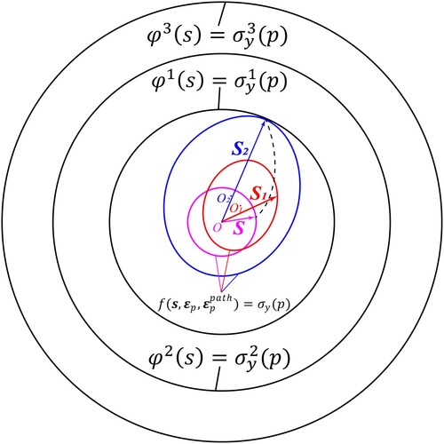
Figure 2. Evolving yield surface and fixed surface of perfect plasticity. Schematic of the evolution of the yield surface until it reaches the fixed surface of perfect plasticity
in ‘5D’ space of deviatoric stresses
at fixed p. The initial yield surface and
are isotropic (circles). Two other yield surfaces depend on
and
, and acquire strain-induced anisotropy, namely shifted centers O1 and O2 (back stress) and ellipsoidal shape due to texture. When the yield surface reaches
, the material deforms like perfectly plastic, isotropic with the fixed surface of perfect plasticity.
2. Materials and methods
The commercially pure (99.8%) α-Zr was heavily pre-deformed to reach the saturation of its hardness. Any method can be used; here, it is obtained by putting a Zr slab with an initial thickness of 5.25 mm into a rolling machine and rolling it 7 times to the thicknesses 3, 2, 1, 0.54, 0.3, 0.206, and 0.163 mm. 3 mm diameter disks were punched out for compression in DAC with rough-DAs, and smooth-DAs for comparison. The pressure distribution is determined using measured lattice parameters through 3rd-order Birch–Murnaghan equation of state from [Citation19]. Samples were compressed gradually up to ∼14-15 GPa at the culet center. In-situ synchrotron XRD in axial diffraction geometry were performed at 16-BM-D beamline at HPCAT at Advanced Photon Source with a wavelength of 0.3100 Å and recorded with Perkin Elmer detector. The measurements were performed along two perpendicular culet diameters (230 µm) in 10 µm steps. The sample current thickness (see Table S1) was measured through x-ray intensity absorption using the linear attenuation equation [Citation19]. The diffraction images were converted to unrolled patterns using FIT2D software [Citation21] and then analyzed through Rietveld refinement using MAUD software [Citation22] to obtain the lattice parameters, volume fractions of ω-Zr, microstrains, crystallite sizes, and dislocation density [Citation23] (see supplementary material).
3. Results and discussion
It is assumed and then proved that after SPD and phase transformation, the initially isotropic polycrystalline Zr deforms as perfectly plastic and isotropic with a strain path-independent surface of the perfect plasticity (Figure ). To determine the pressure dependence of the yield strength of ω-Zr, the pressure distribution of fully transformed region can be used only, i.e. region around culet center of 3 GPa step and the whole diameters after 3 GPa step. Assuming von Mises yield condition with
and considering non-hydrostatic stress and heterogeneity along thickness, the equilibrium equation averaged over thickness is advanced to (see supplementary material):
(1)
(1) where
is the pressure at point
. From Equation Equation(1)
(1)
(1) ,
(2)
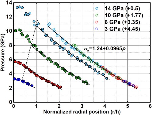
(2) The pressure distributions are plotted vs.
in Figure . To extract the yield strength utilizing data at all compression steps and positions, pressure distributions from different compression stages are shifted horizontally to the same position. Figure shows that for four different compression stages all pressure distributions overlap with each other and are described by Equation Equation(1)
(1)
(1) with single pressure dependence
. Note that
is converted from the hardness of ω-Zr from [Citation24], HV = 3.72 GPa, based on the known relationship
, proving that
is reached with rough-DA. Finite element simulations of the processes in DAC [Citation20, Citation25, Citation26] and Figure S1 demonstrate that for different material positions and compression stages,
,
, and material rotations vary substantially. Consequently, the ability to describe all four curves with single function
demonstrates strict proof, for the first time, that for the monotonous loading with rough-DAs, ω-Zr deforms as perfectly plastic and isotropic material with
and
-independent surface of perfect plasticity. Since
and
are the only reasons for the strain-induced anisotropy, independence of the yield surface of them implies isotropy also from the theory. Similar, friction stress
is also independent of
and
.
Figure 3. Pressure in single-phase ω-Zr vs. r/h. Solid lines correspond to Equation Equation(1)(1)
(1) for
and b = 0.0965. Equation Equation(1)
(1)
(1) is not valid around the culet center due to reduction in friction stress to zero at the symmetry axis. Dashed line shows the position where data is truncated. The unified curve for all loadings (necessary for using data from all four compression stages as a single data set) is obtained by shifting each curve (which is allowed by differential Equation Equation(1)
(1)
(1) ) along the horizontal axis by distance shown in parentheses. Note that uncertainty of pressure as well as crystallite size and dislocation density in the following are smaller than the symbols.
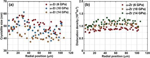
The perfectly plastic behavior is connected with reaching steady nanostructure. After completing phase transformation in the whole sample, crystallite size for 6, 10, and 14 GPa steps scatters between 40 and 60 nm, being practically independent of radius (Figure (a)). Dislocation density
is also practically independent of radius (Figure (b)). Since
,
, and p strongly vary with radius and increasing load, this indicates that steady nanostructure, which is independent of pressure,
and
, is reached. Using the general equation for the yield strength as a combination of the Taylor contribution due to dislocation density and Hall-Petch contribution due to grain size [Citation27], one obtains:
(3)
(3) EquationEq. (3)
(3)
(3) shows consistency between steady states in
and d.
Figure 4. Radial distribution of the crystallite size (a) and dislocation density (b) in ω-Zr for three loading steps after full transformation. Since ,
, and p strongly vary with radius and increasing load, approximate independence of
and
of radius and load indicates that steady nanostructure in terms of crystallite size and dislocation density, which is independent of pressure,
and
, is reached.
Pressure-independence of the steady microstructure is consistent with pressure-independence of hardness for single-phase Zr for and
[Citation12], Ti for
and
[Citation28], and Fe for
and
[Citation11]. After HPT of Ni, at the periphery (where the steady state is reached)
microns for
[Citation2, Citation29], which is within an error and is consistent with the pressure-independent hardness for
[Citation11]. Larger grain size for 1 GPa may be related to not reaching a steady state due to smaller friction and plastic strain. Pressure-independent grain size was reached in V [Citation30], Hf, Pt, Ag, Au, Al, Cu, and Cu-30%Zn [Citation11]. The supplementary material gives some rationales for the pressure independence of the grain size for ω-Zr and difference between known ex-situ and the current in-situ rules. Pressure in single-phase α-Zr is too low to claim pressure independence.
For ω-Zr, with smooth and rough-DA, the steady and
, respectively, and
and
, respectively, are practically the same. A completely different situation is with α-Zr, which has three steady states:
After multiple rolling at ambient pressure, with
and
After deformation with smooth anvils, just before initiation of the α-ω phase transformation at 1.36 GPa, with
After deformation with rough-DA, just before initiation of the α-ω transformation at 0.67 GPa, with
The reason for different steady states cannot be related to the different pressures only because its effect is non-monotonous within a small pressure range. The results about the existence of multiple steady states are consistent with known results that different ways to produce SPD (e.g. HPT, equal-channel angular pressing (ECAP), etc.) lead to different steady grain sizes [Citation1–3, Citation31]. However, different steady dislocation density and crystallite size mean different yield strengths (which could not be determined robustly due to the small number of experimental points for single-phase α-Zr) and surfaces of perfect plasticity
(Figure ). Each of these states was obtained at quite different plastic strain and strain paths, so each of them supposed to be independent of
and
. But if this is true, how can steady
d, and
be different, and which of these steady values should be used in plasticity theory? Thus, the existence of multiple steady states leads to the formulation of a new major challenge in the plasticity and microstructure evolution theories: for which classes of
and
and may be pressure path, material behaves along each of the surfaces
with corresponding steady
and
, and for which loading classes the material behavior jumps from one surface to another with different steady
and
? When this problem is resolved, one will be able to explain why different SPD technologies lead to different steady
and
[Citation1–3, Citation31], and how to design the loading paths to reduce the
, and increase
and strength. One of the potential reasons for different steady states may be related to the qualitatively different character of the plastic flow, like transition from the laminar to hierarchical turbulent flow at different scales with different degrees of complexity [Citation32–34].
Figure 5. Evolving yield surface and several fixed surfaces of perfect plasticity. Part of the schematic with the internal fixed surface of perfect plasticity in ‘5D’ space of deviatoric stresses
at fixed p coincides with that in Figure . The difference is in the presence of several other fixed surfaces of perfect plasticity
with larger yield strengths
.
Importantly, obtained findings are formulated in the language of plasticity theory (plastic strain and strain path tensors, yield surface, etc.) instead of technological language, which allows one to use the obtained knowledge to significantly enrich fundamental plasticity and the formulation and application of plastic models to various processes. In addition, to increase the maximum possible pressure in DAC, toroidal grooves are used [Citation35], which increase friction [Citation18]. This can be done with rough-DAs more uniformly throughout the culet and with smaller stress concentrators.
4. Concluding remarks
In this paper, the first in-situ study of the rules of dislocation density, crystallite size, yield surface, and contact friction under high pressure and SPD is presented. In particular, after some critical plastic strain, ω-Zr behaves like perfectly plastic and isotropic, with fixed plastic strain and the strain-path-independent surface of the perfect plasticity . The perfectly plastic behavior is connected to another rule: crystallite size and dislocation density of α and ω-Zr are getting p (only for ω-Zr),
and
-independent and reach steady values. To provide a robust method to determine
and plastic friction stress, rough-DA with increased height of asperities is introduced here, for which maximum friction
is reached.
Three different steady states are obtained for α-Zr after multiple rolling and with smooth and rough-DAs, all are independent of and
This leads to the new key problem in plasticity theory: for which classes of
, and maybe pressure path material behaves along each of the surfaces
and for which loading classes the material behavior jumps from one surface to another? Solution to this problem will allow one to explain why different SPD technologies lead to different steady grain sizes and dislocation densities and how to design the loading paths to reduce the grain size and increase dislocation density and strength.
Obtained results suggest a more economical way to produce the desired steady nanostructure. Instead of SPD at high pressure, e.g. by HPT, one can reach one of the steady nanostructures by SPD at normal pressure (e.g. by rolling or ECAP) and then reach steady nanostructure with smaller grain size at relatively small plastic strain and low pressure by compression without or with HPT. Since there is a significant reduction in dislocation density and an increase in the crystallite size during pressure reduction [Citation13], the in-situ study shows the potential for further improvement of the microstructure and may help to find an unloading path combined with torsion at low pressures to minimize or eliminate this effect (see also supplementary material). Utilizing rough-DAs in a rotational DAC [Citation36–38] will allow in-situ studies of HPT.
Supplemental Material
Download MS Word (532.3 KB)Acknowledgements
The authors thank (a) Drs. Alexander Zhilyaev and María-Teresa Pérez-Prado for providing Zr sample; (b) Dr. Reinhard Boehler for preparing the surface of rough-DA; (c) Drs. Ashraf Bastawros and Bishoy Dawood for the help with asperity measurement. Support from NSF (CMMI-1943710 and MMN-2246991) is greatly appreciated. This work was performed at HPCAT (Sector 16), Advanced Photon Source (APS), Argonne National Laboratory. HPCAT operations are supported by DOE-NNSA's Office of Experimental Sciences. The Advanced Photon Source is a U.S. Department of Energy (DOE) Office of Science User Facility operated for the DOE Office of Science by Argonne National Laboratory under Contract No. DE-AC02-06CH11357.
Disclosure statement
No potential conflict of interest was reported by the author(s).
Data availability
The data of this study is available from the corresponding authors upon request.
Additional information
Funding
References
- Edalati K, Bachmaier A, Beloshenko VA, et al. Nanomaterials by severe plastic deformation: review of historical developments and recent advances. Mater Res Lett. 2022;10(4):163–256. doi:10.1080/21663831.2022.2029779
- Zhilyaev AP, Langdon TG. Using high-pressure torsion for metal processing: Fundamentals and applications. Prog Mater Sci. 2008;53:893–979. doi:10.1016/j.pmatsci.2008.03.002
- Pippan R, Scheriau S, Taylor A, et al. Saturation of fragmentation during severe plastic deformation. Annu Rev Mater Res. 2010;40:319–343. doi:10.1146/annurev-matsci-070909-104445
- Cao Y, Ni S, Liao X, et al. Structural evolutions of metallic materials processed by severe plastic deformation. Mater Sci Eng R Rep. 2018;133:1–59. doi:10.1016/j.mser.2018.06.001
- Valiev RZ, Estrin Y, Horita Z, et al. Producing bulk ultrafine-grained materials by severe plastic deformation. JOM. 2006;58:33–39. doi:10.1007/s11837-006-0213-7
- Ovid'Ko IA, Valiev RZ, Zhu YT. Review on superior strength and enhanced ductility of metallic nanomaterials. Prog Mater Sci. 2018;94:462–540. doi:10.1016/j.pmatsci.2018.02.002
- Valiev RZ, Estrin Y, Horita Z, et al. Producing bulk ultrafine-grained materials by severe plastic deformation: ten years later. JOM. 2016;68:1216–1226. doi:10.1007/s11837-016-1820-6
- Zhu YT, Langdon TG. The fundamentals of nanostructured materials processed by severe plastic deformation. JOM. 2004;56(10):58–63. doi:10.1007/s11837-004-0294-0
- Girard J, Amulele G, Farla R, et al. Shear deformation of bridgmanite and magnesiowüstite aggregates at lower mantle conditions. Science. 2016;351(6269):144–147. doi:10.1126/science.aad3113
- Levitas VI. Resolving puzzles of the phase-transformation-based mechanism of the strong deep-focus earthquake. Nat Commun. 2022;13(1):6291. doi:10.1038/s41467-022-33802-y
- Edalati K, Horita Z. Universal plot for hardness variation in pure metals processed by high-pressure torsion. Mater Trans. 2010;51:1051–1054. doi:10.2320/matertrans.M2009431
- Edalati K, Horita Z, Yagi S, et al. Allotropic phase transformation of pure zirconium by high-pressure torsion. Mater Sci Eng A. 2009;523:277–281. doi:10.1016/j.msea.2009.07.029
- Kerber MB, Spieckermann F, Schuster R, et al. In situ synchrotron X-Ray diffraction during high-pressure torsion deformation of Ni and NiTi. Adv Eng Mater. 2021;23:2100159. doi:10.1002/adem.202100159
- Pandey KK, Levitas VI, Park C. Effect of the initial microstructure on the pressure-induced phase transition in Zr and microstructure evolution. 2023. 25 p. Located at: https://arxiv.org/abs/2301.10475.
- Lin F, Hilairet N, Raterron P, et al. Elasto-viscoplastic self consistent modeling of the ambient temperature plastic behavior of periclase deformed up to 5.4 GPa. J Appl Phys. 2017;122:205902. doi:10.1063/1.4999951
- Meade C, Jeanloz R. The strength of mantle silicates at high pressures and room temperature: implications for the viscosity of the mantle. Nature. 1990;348:533–535. doi:10.1038/348533a0
- Meade C, Jeanloz R. Effect of a coordination change on the strength of amorphous SiO2. Science. 1988;241(4869):1072–1074. doi:10.1126/science.241.4869.1072
- Levitas VI. Large deformation of materials with complex rheological properties at normal and high pressure. New York (NY): Nova Science; 1996.
- Pandey KK, Levitas VI. In situ quantitative study of plastic strain-induced phase transformations under high pressure: Example for ultra-pure Zr. Acta Mater. 2020;196:338–346. doi:10.1016/j.actamat.2020.06.015
- Levitas VI, Kamrani M, Feng B. Tensorial stress−strain fields and large elastoplasticity as well as friction in diamond anvil cell up to 400 GPa. NPJ Comput Mater. 2019;5(1):94), doi:10.1038/s41524-019-0234-8
- Hammersley AP. FIT2D: an introduction and overview. European synchrotron radiation facility internal report ESRF97HA02 T 1997; 68:58.
- Lutterotti L, Matthies S, Wenk HR, et al. Combined texture and structure analysis of deformed limestone from time-of-flight neutron diffraction spectra. J Appl Phys. 1997;81(2):594–600. doi:10.1063/1.364220
- Williamson GK, Smallman RE. III. Dislocation densities in some annealed and cold-worked metals from measurements on the X-ray debye-scherrer spectrum. Philos Mag. 1956;1(1):34–46. doi:10.1080/14786435608238074
- Pérez-Prado MT, Zhilyaev AP. First experimental observation of shear induced hcp to bcc transformation in pure Zr. Phys Rev Lett. 2009;102(17):175504. doi:10.1103/PhysRevLett.102.175504
- Levitas VI, Zarechnyy OM. Modeling and simulation of strain-induced phase transformations under compression in a diamond anvil cell. Phys Rev B. 2010;82(17):174123. doi:10.1103/PhysRevB.82.174123
- Levitas VI, Dhar A, Pandey KK. Tensorial stress-plastic strain fields in α-ω Zr mixture, transformation kinetics, and friction in diamond anvil cell. 2023. 32 p. Located at: doi:10.48550/arXiv.2212.13000.
- Voyiadjis GZ, Yaghoobi M. Size effects in plasticity: from macro to nano. Cambridge: Academic Press; 2019.
- Edalati K, Matsubara E, Horita Z. Processing pure Ti by high-pressure torsion in wide ranges of pressures and strain. Metall Mater Trans A. 2009;40:2079–2086. doi:10.1007/s11661-009-9890-5
- Zhilyaev AP, Nurislamova GV, Kim BK, et al. Experimental parameters influencing grain refinement and microstructural evolution during high-pressure torsion. Acta Mater. 2003;51:753–765. doi:10.1016/S1359-6454(02)00466-4
- Lee S, Edalati K, Horita Z. Microstructures and mechanical properties of pure V and Mo processed by high-pressure torsion. Mater Trans. 2010;51:1072–1079. doi:10.2320/matertrans.M2009375
- Razumov IK, Yermakov AY, Gornostyrev YN, et al. Nonequilibrium phase transformations in alloys under severe plastic deformation. Phys-Usp. 2020;63(8):733. doi:10.3367/UFNe.2019.10.038671
- Cao Y, Kawasaki M, Wang YB, et al. Unusual macroscopic shearing patterns observed in metals processed by high-pressure torsion. J Mater Sci. 2010;45:4545–4553. doi:10.1007/s10853-010-4485-5
- Cao Y, Wang YB, Figueiredo RB, et al. Three-dimensional shear-strain patterns induced by high-pressure torsion and their impact on hardness evolution. Acta Mater. 2011;59:3903–3914. doi:10.1016/j.actamat.2011.03.015
- Beygelzimer Y, Filippov A, Estrin Y. Turbulent’ shear flow of solids under high-pressure torsion. Philos Mag. 2023: 1–12.
- Jenei Z, O’Bannon EF, Weir ST, et al. Single crystal toroidal diamond anvils for high pressure experiments beyond 5 megabar. Nat Commun. 2018;9(1):3563. doi:10.1038/s41467-018-06071-x
- Ji C, Levitas VI, Zhu H, et al. Shear-induced phase transition of nanocrystalline hexagonal boron nitride to wurtzitic structure at room temperature and lower pressure. Proc Natl Acad Sci U S A. 2012;109(47):19108–19112. doi:10.1073/pnas.1214976109
- Gao Y, Ma Y, An Q, et al. Shear driven formation of nano-diamonds at sub-gigapascals and 300 K. Carbon N Y. 2019;146:364–368.
- Levitas VI. High-pressure phase transformations under severe plastic deformation by torsion in rotational anvils. Mater Trans. 2019;60(7):1294–1301. doi:10.2320/matertrans.MF201923