
 ?Mathematical formulae have been encoded as MathML and are displayed in this HTML version using MathJax in order to improve their display. Uncheck the box to turn MathJax off. This feature requires Javascript. Click on a formula to zoom.
ABSTRACT
The formation of microcracks at the interface of steel–copper heterostructures is prone to premature failure, which severely limits the application of heterostructure components. Herein, a new approach was proposed by doping nano-TiC in interface forming by laser powder bed fusion (L-PBF) to prevent the hot crack nucleation and block the solid-state crack propagation in steel–copper heterostructures . Benefitting from the TiC doping, the tensile strength of laminated steel–copper structures increased from 372 to 526 MPa. The findings of this research present a new approach to inhibit cracking in the fabrication of heterostructure component manufacturing using L-PBF.
GRAPHICAL ABSTRACT
IMPACT STATEMENT
By doping nano-TiC particles into the steel–copper bimetallic interface, Hot crack nucleation and solid-state crack propagation were inhibited, and the crack-free steel–copper heterostructures were successfully prepared using LPBF.
Introduction
Steel–copper components with excellent mechanical strength and high thermal and electrical conduction play an essential role in bearings, oil/gas pipelines and electronic communication applications [Citation1,Citation2]. However, cracks were often reported at the interfacial zone due to high solidification cracking susceptibility [Citation3] and limited solid solubility [Citation4] between steel and copper. Previous studies showed that microcracks cannot be eliminated in the steel–copper samples prepared by conventional methods, such as powder metallurgy [Citation5], joining process [Citation6] and continuous casting [Citation7]. In these technologies, solidification cracking was the primary cracking mechanism, where low-melting point phases are polarized along the grain boundaries and form liquid films [Citation8,Citation9]. Cracking occurs when the localized stress causes the liquid film to tear from the matrix [Citation10,Citation11]. In addition, nearly all these approaches have great difficulties in forming spatially complex heterostructure components which were not applicable to the steel–copper parts for practical applications.
The laser powder bed fusion (LPBF) technology allows the preparation of complex heterostructure parts by alternating deposition of multiple powdered materials [Citation12]. However, due to the internal strain accumulation caused by thermal cycling and columnar grain morphology along the building direction (BD), hot cracks tended to generate and propagate along the long and straight columnar grain boundaries [Citation13–15]. Han et al. [Citation16] fabricated Hastelloy X by LPBF and found that hot microcracks usually occurred along high-angle grain boundaries and the liquid film pressure was critical for the formation of hot cracking. Theoretically, hot cracks can be completely avoided by decreasing the volume of liquid film and alleviating the stress concentration of susceptible areas (neighbouring dendritic spaces) at the end of solidification [Citation17]. For example, the addition of Ti, Sc and Zr solutes to aluminium alloys could reduce the content of the inter-dendritic low-melting liquid film and obtain fine microstructures to accommodate the stress, thereby inhibiting cracking [Citation18–20]. Similarly, TiC particles with good wettability with molten copper and steel were expected for steel–copper interface crack suppression [Citation21,Citation22]. However, inoculation treatment for dissimilar material interfaces manufactured by LPBF has rarely been studied.
In this work, the nano-TiC particles were added into a bimetallic interface formed by LPBF. The laminated steel–copper structures were manufactured to demonstrate the effect of nano-TiC particles on crack inhibition. Detailed microscopic characterization and macroscopic mechanical tests revealed the mechanism of TiC inhibition of steel–copper interfacial cracking.
Materials and methods
The 316L and CuSn10 powders were prepared by gas atomization (Shenzhen Minatech Additive Manufacturing Co., Ltd, China) in this experiment. The raw powder size (Malvern, UK) varied from 20.5 to 53.2 μm and from 18.2 to 49.9 μm, respectively (Figure S1(a,b) in SI). TiC had an average particle size of 800 nm (Figure S1(c)). A high-speed mixer (QM-3SP4, Nanjing NanDa Instrument Plant, China) was employed to prepare 316L-2 wt.% TiC composite feedstock. The weight ratio of ball and powder and the rotational speed were 3:1 and 400 rpm, respectively. After 10 h of ball milling, the TiC particles were evenly dispersed in the 316L matrix without apparent aggregation (Figure S1(d–i)). The steel–copper heterostructure was formed using HK M125 equipment (Wuhan Huake 3D Technology Co., Ltd., China). As illustrated in Figure (a), the process of steel–copper heterostructures was (1) the six layers of 316L + TiC powders were spread on the 316L substrate, and then the bulk parts were fabricated, (2) the six layers of CuSn10 parts were prepared and (3) the steps (1) and (2) were repeated alternately until the formation of the steel–copper heterostructure was completed. The parameters of 316L + TiC and CuSn10 parts were applied: laser powers of 340 and 400 W; scanning speeds of 630 and 500 mm/s; layer thickness of 50 μm; hatch spacings of 120 μm; 67° rotation scanning strategy (Figure S2). Sample sizes for mechanical testing and microscopic characterization were 70 mm ×10 mm ×10 mm and 10 mm ×10 mm ×10 mm, respectively. The heterostructures without TiC doping were named Group A, and the structures with TiC doping were named Group B.
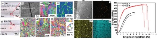
Figure 1. (a) Schematics showing the processes of steel–copper heterostructures by LPBF; (b) OM image; (c) high magnification SEM image; (d) EBSD-IPF map and (e) KAM map of the Group A samples; (f) OM image of Group B samples; (g–i) EBSD-IPF maps corresponding to areas in Figure (f).
For the microstructure analyses, the middle region of samples was selected for the microscopic characterization, but the conclusions can be applied to any steel–copper interface of the samples. The microstructure of the sample was characterized by optical microscopy (OM, Olympus BX60, Germany) and scanning electron microscopy (SEM, Quanta 650 FEG, USA). Electron back-scattered diffraction (EBSD, Li3 Aztec Nordlys Max3) under a 20 kV acceleration voltage was performed for grain orientation mapping. The distribution of TiC particles and interfacial structure were observed by a transmission electron microscope (TEM, Tecnai G2 F30 S-TWIN) at an acceleration voltage of 300 kV. Samples for TEM analysis were prepared with focused ion beam (FIB) machining in FEI Helios Nanolab600i FIB-SEM. The mechanical property of the dog-bone-shaped sample (Figure S2) was evaluated by tensile test using a Zwick/Roell Z020 universal testing machine at a strain rate of 10−3 s−1.
Results and discussion
The microstructures of two sets of samples are shown in Figure . Long and straight macroscopic cracks parallel to the BD were observed in Group A samples (Figure (b)). These cracks originated from the interfacial mixed zone, where the hot cracks were prone to occur due to the low miscibility between the steel and copper [Citation3,Citation23], and propagated along the straight columnar dendrite boundaries (Figure (c,d)). Figure (e) shows the KAM map, where the strain in the vicinity of cracks was obviously higher than that inside the columnar grains, indicating severe stresses in the intergranular region at the end of solidification. Severe localized stresses promoted the formation and expansion of hot cracks [Citation14].
While the TiC was added at the 316L side, cracks were significantly suppressed (Figure (f)). In the 316L region of Group B samples, grains elongated along the centre of the molten pool (Figure (g)) were observed, which were quite different from the grains shown in Figure (d), where the textured coarse grain structure dominated the vertical plane. In the SEM images, large columnar structures and epitaxial growth were visible in the 316L region of Group A samples, while the 316L region of Group B samples exhibited the cell structures throughout the melt pool (Figure S3). The nano-TiC particles acted as heterogeneous nucleation sites during solidification, which significantly increased the crystal nucleation rate of the 316L matrix and thereby grain refinement [Citation24–26]. The refined microstructure in Figure (g) contained more tortuous grain boundaries, which were not conducive to crack propagation, and cracks tended to be effectively suppressed [Citation27]. Notably, ultrafine equiaxed grains were observed in the diffusion zone (Figure (h)), which effectively inhibited the crack propagation into the CuSn10 region. In the CuSn10 region away from the interface, columnar grains along the BD were observed (Figure (i)). This epitaxial growth of grains across multiple molten pools due to a smaller crystal growth barrier was common in samples fabricated by LPBF [Citation28].
Samples for TEM analysis were obtained by FIB cutting at selected areas of the steel–copper interface. Figure (a) shows the bright-field TEM (BF-TEM) view, where the steel–copper interface was clearly visible. The corresponding selected area electron diffraction pattern (SADP) demonstrated the crystallographic relationship between the γ-Fe and ϵ-Cu, where the crystal axes were parallel to each other: [10] Cu || [1
0] Fe. Figure (b) shows a HAADF-STEM image and corresponding EDS maps on the 316L side of the sample. Black spherical TiC particles and white irregular Cu-rich phases could be observed in the 316L matrix, as confirmed by the EDS maps. Most of these nanosized TiC particles tended to diffuse into the Cu-rich phases during solidification, as shown by the yellow circle in Figure (b). The EDS mapping in Figure S4 showed that elements Ti and C had the characteristic distribution along the cell boundaries, while elements, such as Fe, Ni and Cr, were uniformly distributed in the field of view. Therefore, in the final stage of solidification, these particles easily migrated to the cell and grain boundaries under convection and contributed to a decrease in the volume of the liquid film, thus reducing the hot cracking [Citation17].
Figure 2. (a) BF-TEM images and SADP patterns of the steel–copper interface; (b) HAADF-STEM image showing the TiC particles distribution at the steel–copper interface and the corresponding EDS maps of Ti, Cu, Fe and Ni; (c) HRTEM image taken at the TiC/Cu interface along the [10] zone axis of Cu; (d) the corresponding FFT pattern of Figure (c); (e) IFFT pattern corresponds to the white rectangle in Figure (d); (f) HRTEM image taken at the TiC/Fe interface along the [1
0] zone axis of Fe; (g) the corresponding FFT pattern of Figure (f); (h) IFFT pattern corresponds to the white rectangle in Figure (g).
![Figure 2. (a) BF-TEM images and SADP patterns of the steel–copper interface; (b) HAADF-STEM image showing the TiC particles distribution at the steel–copper interface and the corresponding EDS maps of Ti, Cu, Fe and Ni; (c) HRTEM image taken at the TiC/Cu interface along the [101¯] zone axis of Cu; (d) the corresponding FFT pattern of Figure 2(c); (e) IFFT pattern corresponds to the white rectangle in Figure 2(d); (f) HRTEM image taken at the TiC/Fe interface along the [11¯0] zone axis of Fe; (g) the corresponding FFT pattern of Figure 2(f); (h) IFFT pattern corresponds to the white rectangle in Figure 2(g).](/cms/asset/8382054b-8b8a-48d4-9853-1c80fe7cc69e/tmrl_a_2264346_f0002_oc.jpg)
Figure (c,f) shows the high-resolution TEM (HRTEM) images of the interface of TiC/Cu and TiC/Fe, where the incident electron beam was along the [10] zone axis of Cu and [1
0] zone axis of Fe, respectively. The superlattice reflections of TiC particles could be observed from the FFT pattern (Figure (d,g)). The IFFT patterns of (111) filtered Cu and (200) filtered TiC in Figure (e) indicated a semi-coherent interface between the Cu and TiC, where a few dislocations could be observed at the interface. Figure (h) exhibits the IFFT patterns of (111) filtered of Fe and (200) filtered TiC. The Fe–TiC interfacial contained more dislocations and was accompanied by a greater grain misfit angle compared to Cu–TiC, which suggested a lower interface energy at Cu–TiC. As a result, in the steel–copper transition zone, TiC tended to aggregate with the Cu-rich phase, which was beneficial for relieving the thermal residual strain between neighbouring grains [Citation29].
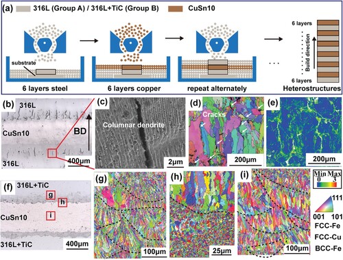
To investigate the influence of interfacial TiC doping on the mechanical performance of steel–copper heterostructures, the laminated steel–copper samples were prepared and tested in tension (Figure ). The Group B samples with TiC doping showed an improved tensile strength (UTS of 526 MPa) and total elongation (EI of 9.8%) than the Group A samples (UTS of 372 MPa and EI of 5.7%, Figure (a)). The post-fracture sample analysis revealed that no slip or twinning deformation was found in Group A samples (Figure (d)), which indicated that the samples had been fractured before plastic deformation occurred. The KAM map shown in Figure (e) exhibited larger values in the fine-grain region and cracked edges of CuSn10. This indicated that the strain concentration occurred near the pre-existing microcracks in the 316L region and subsequently extended into the CuSn10 region. The fracture morphology of Group A samples (Figure (h,i)) exhibited the typical cleavage pattern and equiaxial dimples in 316L and CuSn10 regions, respectively. The former was closely related to the propagation of microcracks, while the latter indicated the plastic deformation in the CuSn10 region.
Figure 3. (a) Stress-strain plots of samples; macroscopic fracture surface of Group A and Group B samples (b) and (c), respectively; (d) EBSD-IPF combined with band contrast map and (e) KAM map of the Group A samples; (f) EBSD-IPF combined with band contrast map and (g) KAM map of the Group B samples; (h) and (i) SEM of fracture surface of 316L and CuSn10 regions in Group A samples, respectively; (j) and (k) SEM of the fracture surface of 316L and CuSn10 regions in Group A samples, respectively.
It was worth mentioning that in Group B fracture samples with TiC doping, macroscopic cracks were also found in the 316L region (Figure (f,g)). However, we believe that the cracks shown in Figure (f) were generated during the tensile process because the previous microstructural characterization of the samples did not reveal the presence of similar cracks (Figure ). Considering the segregation of impurities [Citation30,Citation31] and the anisotropy of columnar grains [Citation32], cracks first nucleated at the columnar grain boundaries and then expanded rapidly along the grain boundaries. The fracture morphology in the 316L region of Group B samples (Figure (j)) showed the obvious intergranular mode. The fracture surface was smooth and showed no cleavage features, which means that cracks were generated and developed rapidly along the columnar grain boundaries [Citation33]. The dimples demonstrated that ductile fracture dominated the CuSn10 region, as shown in Figure (k).
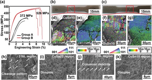
The crack formation and inhibition mechanism were schematically illustrated in Figure . In the steel–copper interface, the strong circular flow in the melt pool led to dissimilar elements mixing well during the LPBF process (Figure (a)). As the solidification process proceeded, the Fe-rich phase in the mixing zone nucleated preferentially and developed into fine dendrites, which contributed to the grain refinement of the liquid Cu (Figure (b)). At the end of the solidification, the remaining liquid Cu film existed between the solidified dendrites. Meanwhile, a large tensile stress developed by the shrinkage during solidification was concentrated near the liquid film [Citation10]. Solidification cracking occurs when the localized tensile stresses exceed the material resistance to cracking [Citation13]. Usually, solidification cracking resulted in a significant gap between two surfaces, which had an irregular shape (Figure S5(a)). The separation only occurred when the liquid was insufficient to accommodate the shrinkage strain (Figure S5(b)). When the temperature dropped to a relatively low- temperature range, solid-state cracking nucleated based on pre-existing solidification cracks because of the obvious stress concentration at the tip of the cracks and propagated rapidly along the large columnar grain boundaries [Citation33] (red arrows in Figure (c)). These cracks were typically characterized by a straight and neat morphology, and often accompanied by sharp kinks (Figure S5(d–f)). As a result, massive cracks parallel to the BD were observed in laminated steel–copper components at room temperature (Figure (d)).
Figure 4. Schematic diagram of the crack formation and inhibition in the 316L–CuSn10 interface. (a–d) crack formation and extension at the 316L–CuSn10 interface; (e–h) cracks inhibit at the 316L–CuSn10 interface with TiC doping.
In the steel–copper interface with TiC doping, liquid Cu, re-melted liquid Fe and in-suit formed nanosized TiC particles coexisted in the mixed zone (Figure (e)). When the temperature decreased, a few TiC particles were encapsulated in the Fe-rich fine dendrites, while most of them remained in the liquid Cu (Figure (f)). There was a high probability that these particles would travel with liquid Cu into the adjacent dendrite spaces. These nanosized TiC particles contributed to reducing the volume of the intergranular liquid Cu film (i.e. less liquid supply required into the intergranular region) and the stress concentration near the Cu liquid film, consequently eliminating hot cracking [Citation10,Citation34,Citation35]. On the other hand, cracks were more likely to propagate at coarse columnar grains because their lower coalescence temperature favoured the accumulation of liquid, which led to the stress concentration and crack extension [Citation36]. TiC doping led to significant grain refinement and a more random grain morphology in the steel zone, which prevented the extension of low-temperature solid-state cracking [Citation37], as indicated by the red arrow in Figure (g). In as-built laminated steel–copper components, cracks were almost completely suppressed (Figure (h)).
Conclusion
The crack-free steel–copper heterostructures were prepared successfully via LPBF by doping TiC into the steel and copper interface. In the mixing zone at the steel–copper interface, TiC tended to aggregate with the Cu-rich phase due to the lower interfacial energy. Therefore, in the final stages of solidification, the TiC particles aggregated at grain boundaries could reduce the volume of the intergranular liquid Cu film and stress concentration, which reduced the nucleation and progression of hot cracks in the steel–copper mixed zone. Besides, the solid-state crack extension was blocked by tortuous grain boundaries in the steel zone due to the grain refinement of TiC. Benefitting from the TiC doping, the tensile strength of laminated steel–copper structures increased from 372 to 526 MPa. The findings of this research can serve as a reference for the suppression of cracking at dissimilar-material interfaces using LPBF.
Supplemental Material
Download MS Word (2.9 MB)Disclosure statement
No potential conflict of interest was reported by the author(s).
Additional information
Funding
References
- Kar J, Roy SK, Roy GG. Effect of beam oscillation on electron beam welding of copper with AISI-304 stainless steel. J Mater Process Technol. 2016;233:174–185. doi:10.1016/j.jmatprotec.2016.03.001
- Zhang H, Jiao KX, Zhang JL, et al. Experimental and numerical investigations of interface characteristics of copper/steel composite prepared by explosive welding. Mater Des. 2018;154:140–152. doi:10.1016/j.matdes.2018.05.027
- Bai Y, Zhang J, Zhao C, et al. Dual interfacial characterization and property in multi-material selective laser melting of 316L stainless steel and C52400 copper alloy. Mater Charact. 2020;167:110489. doi:10.1016/j.matchar.2020.110489
- Zhang X, Pan T, Chen Y, et al. Additive manufacturing of copper-stainless steel hybrid components using laser-aided directed energy deposition. J Mater Sci Technol. 2021;80:100–116. doi:10.1016/j.jmst.2020.11.048
- Masahashi N, Semboshi S, Watanabe K, et al. Solid-state bonding of alloy-designed Cu–Zn brass and steel associated with phase transformation by spark plasma sintering. J Mater Sci. 2013;48(17):5801–5809. doi:10.1007/s10853-013-7372-z
- Gladkovsky SV, Kuteneva SV, Sergeev SN. Microstructure and mechanical properties of sandwich copper/steel composites produced by explosive welding. Mater Charact. 2019;154:294–303. doi:10.1016/j.matchar.2019.06.008
- Jie J, Liu C, Wang S, et al. Characterisation of steel/nickel bronze clad strips prepared by continuous solid/liquid bonding method. Mater Sci Technol 2019;35(15):1840–1847. doi:10.1080/02670836.2019.1651015
- Tang YT, Panwisawas C, Ghoussoub JN, et al. Alloys-by-design: application to new superalloys for additive manufacturing. Acta Mater. 2021;202:417–436. doi:10.1016/j.actamat.2020.09.023
- Pellizzari M, AlMangour B, Benedetti M, et al. Effects of building direction and defect sensitivity on the fatigue behavior of additively manufactured H13 tool steel. Theor Appl Fract Mech. 2020;108:102634. doi:10.1016/j.tafmec.2020.102634
- Fu J, Li H, Song X, et al. Multi-scale defects in powder-based additively manufactured metals and alloys. J Mater Sci Technol. 2022;122:165–199. doi:10.1016/j.jmst.2022.02.015
- Deirmina F, AlMangour B, Grzesiak D, et al. H13–partially stabilized zirconia nanocomposites fabricated by high-energy mechanical milling and selective laser melting. Mater Des. 2018;146:286–297. doi:10.1016/j.matdes.2018.03.017
- Liu ZY, Zhao DD, Wang P, et al. Additive manufacturing of metals: microstructure evolution and multistage control. J Mater Sci Technol. 2022;100:224–236. doi:10.1016/j.jmst.2021.06.011
- Chauvet E, Kontis P, Jägle EA, et al. Hot cracking mechanism affecting a non-weldable Ni-based superalloy produced by selective electron beam melting. Acta Mater. 2018;142:82–94. doi:10.1016/j.actamat.2017.09.047
- Lu N, Lei Z, Hu K, et al. Hot cracking behavior and mechanism of a third-generation Ni-based single-crystal superalloy during directed energy deposition. Addit Manuf. 2020;34:101228. doi:10.1016/j.addma.2020.101228
- Zhou Z, Huang L, Shang Y, et al. Causes analysis on cracks in nickel-based single crystal superalloy fabricated by laser powder deposition additive manufacturing. Mater Des. 2018;160:1238–1249. doi:10.1016/j.matdes.2018.10.042
- Han Q, Mertens R, Montero-Sistiaga ML, et al. Laser powder bed fusion of Hastelloy X: effects of hot isostatic pressing and the hot cracking mechanism. Mater Sci Eng A. 2018;732:228–239. doi:10.1016/j.msea.2018.07.008
- Zhao Y, Ma Z, Yu L, et al. New alloy design approach to inhibiting hot cracking in laser additive manufactured nickel-based superalloys. Acta Mater. 2023;247:118736. doi:10.1016/j.actamat.2023.118736
- Martin JH, Yahata BD, Hundley JM, et al. 3D printing of high-strength aluminium alloys. Nature. 2017;549(7672):365–369. doi:10.1038/nature23894
- Tan Q, Zhang J, Sun Q, et al. Inoculation treatment of an additively manufactured 2024 aluminium alloy with titanium nanoparticles. Acta Mater. 2020;196:1–16. doi:10.1016/j.actamat.2020.06.026
- Li R, Wang M, Li Z, et al. Developing a high-strength Al-Mg-Si-Sc-Zr alloy for selective laser melting: crack-inhibiting and multiple strengthening mechanisms. Acta Mater. 2020;193:83–98. doi:10.1016/j.actamat.2020.03.060
- AlMangour B, Baek M-S, Grzesiak D, et al. Strengthening of stainless steel by titanium carbide addition and grain refinement during selective laser melting. Mater Sci Eng A. 2018;712:812–818. doi:10.1016/j.msea.2017.11.126
- Zhai W, Zhou W, Nai SML. Grain refinement and strengthening of 316L stainless steel through addition of TiC nanoparticles and selective laser melting. Mater Sci Eng A. 2022;832:142460. doi:10.1016/j.msea.2021.142460
- Wang S, Chen C, Ju J, et al. Suppression of LME cracks in Sn bronze-steel system based on multi-material additive manufacturing. Mater Lett. 2023;335:133775. doi:10.1016/j.matlet.2022.133775
- Zhai W, Zhu Z, Zhou W, et al. Selective laser melting of dispersed TiC particles strengthened 316L stainless steel. Compos B Eng. 2020;199:108291. doi:10.1016/j.compositesb.2020.108291
- AlMangour B, Grzesiak D, Borkar T, et al. Densification behavior, microstructural evolution, and mechanical properties of TiC/316L stainless steel nanocomposites fabricated by selective laser melting. Mater Des. 2018;138:119–128. doi:10.1016/j.matdes.2017.10.039
- Biedunkiewicz A, Biedunkiewicz W, Figiel P, et al. Preparation of stainless steel-TiC composite by selective laser melting. Chem Listy. 2011;105:773–774.8.
- Li N, Wang T, Zhang L, et al. Crack initiation mechanism of laser powder bed fusion additive manufactured Al-Zn-Mg-Cu alloy. Mater Charact. 2023;195:112415. doi:10.1016/j.matchar.2022.112415
- Hu Z, Yang Z, Du Z, et al. Effect of scanning strategy on the anisotropy in microstructure and properties of Cu-Cr-Zr alloy manufactured by laser powder bed fusion. J Alloy Compd. 2022;920:165957. doi:10.1016/j.jallcom.2022.165957
- Wang N, Mokadem S, Rappaz M, et al. Solidification cracking of superalloy single- and bi-crystals. Acta Mater. 2004;52(11):3173–3182. doi:10.1016/j.actamat.2004.03.047
- Liu Y, Zhang J, Tan Q, et al. Additive manufacturing of high strength copper alloy with heterogeneous grain structure through laser powder bed fusion. Acta Mater. 2021;220:10. doi:10.1016/j.actamat.2021.117311
- Huang J, Li W, He J, et al. Dual heterogeneous structure facilitating an excellent strength-ductility combination in an additively manufactured multi-principal-element alloy. Mater Res Lett. 2022;10:(9):575–584. doi:10.1080/21663831.2022.2067790
- Deng J, Chen C, Liu X, et al. A high-strength heat-resistant Al5.7Ni eutectic alloy with spherical Al3Ni nano-particles by selective laser melting. Scr Mater. 2021;203:(4):114034. doi:10.1016/j.scriptamat.2021.114034
- Zhang X, Chen H, Xu L, et al. Cracking mechanism and susceptibility of laser melting deposited Inconel 738 superalloy. Mater Des. 2019;183:108105. doi:10.1016/j.matdes.2019.108105
- Mandal V, Tripathi P, Kumar A, et al. A study on selective laser melting (SLM) of TiC and B4C reinforced IN718 metal matrix composites (MMCs). J Alloys Compd. 2022;901:163527. doi:10.1016/j.jallcom.2021.163527
- Zhao Z, Li J, Bai P, et al. Microstructure and mechanical properties of TiC-reinforced 316L stainless steel composites fabricated using selective laser melting. Metals. 2019;9:(2):267. doi:10.3390/met9020267
- Vilanova M, Taboada MC, Martinez-Amesti A, et al. Influence of minor alloying element additions on the crack susceptibility of a nickel based superalloy manufactured by LPBF. Materials. 2021;14(19):5702. doi:10.3390/ma14195702
- Fereiduni E, Yakout M, Elbestawi M. Additive manufacturing of emerging materials. In: Process-structure-property relationships in additively manufactured metal matrix composites. Cambridge.: Springer; 2019. p. 111–177.