
 ?Mathematical formulae have been encoded as MathML and are displayed in this HTML version using MathJax in order to improve their display. Uncheck the box to turn MathJax off. This feature requires Javascript. Click on a formula to zoom.
Abstract
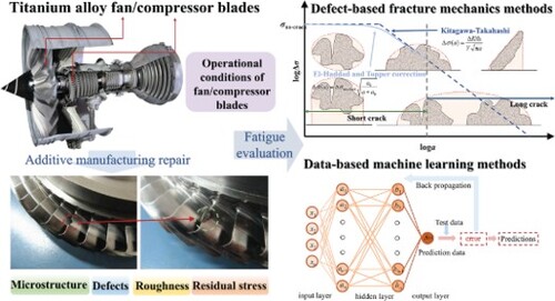
The aviation industry is a key market that promote additive manufacturing (AM) technology since there are huge demands for precision manufacture of high-value complex structural parts and repair of local defects. Extensive research has been conducted on AM process, characterization, and fatigue evaluation of titanium alloy, but there are rare comprehensive reviews on fatigue evaluation methods used for AM aero-engine blades. Rigorous tests, evaluation, and certification are necessary before AM technology is applied in aero-engine blade repair, although it has shown great advantages in different engineering fields. This paper introduces the application of AM technology in the manufacturing and repair of aero-engine titanium alloy blades, summarizes the key factors affecting the fatigue performance of AM titanium alloys, thoroughly discusses the fatigue mechanism, research methods, and process optimizations of AM parts, and compares the differences among several prediction models in fatigue evaluation of AM titanium alloys.
Abbreviations: FOD: foreign object damage; LCF: low cycle fatigue; HCF: high cycle fatigue; LSP: laser shock peening; SP: shot peening; LP: low-pressure; HAZ: heat affected zone; AM: additive manufacturing; LAM: laser additive manufacturing; DED: directed energy deposition; PBF: powder bed fusion; LPBF: laser powder bed fusion; EPBF: electron beam powder bed fusion; LMD: laser metal deposition; LCD: laser cladding deposition; LENS: laser engineered net shaping; SLM: selective laser melting; EBM: electron beam melting; SEBM: selective electron beam melting; SLS: selective laser sintering; DMLS: direct Metal Laser Sintering; DMD-L: direct metal deposition by laser; DMD-P: direct metal deposition by plasma arc; LS: laser sintering; AB: as-built; LOF: lack of fusion; EVS: extreme value statistics; LEVD: largest extreme value distribution; VED: volumetric energy density; PD: probabilistic distribution; MRO: maintenance, repair & operations; STA: solution treatment & aging; BUS: broken-up structure; HIP: hot isostatic pressing; M&P: machining and polishing; SR: stress relief; AN: annealing; DAN: double annealing; PBG: prior β grain; TCT: thermochemical treatment; AC: air cooling; SMAT: surface mechanical attrition treatment; CT: computer tomography; SEM: scanning electron microscope; FCG: fatigue crack propagation; FCGR: fatigue crack propagation rate; SIF: stress intensity factor; EIFS: equivalent initial defect size; LEFM: linear elastic fracture mechanics; ML: machine learning; ANN: artificial neural network; FNN: feed forward neural network; CNN: convolutional neural network; PINN: physics-informed neural network; PPgNN: probabilistic physics-guided neural network; ANFS: adaptive network-based fuzzy system; SVM: support vector machine; SVR: support vector regression; RF: random forest; CDM: continuum damage mechanics.
IMPACT STATEMENT
The fatigue performance of additively manufactured titanium alloys is influenced by a combination of microstructure, defects, surface roughness, and residual stresses. In the context of fatigue assessment, the role of defects is typically prioritized.
GRAPHICAL ABSTRACT
1. Introduction
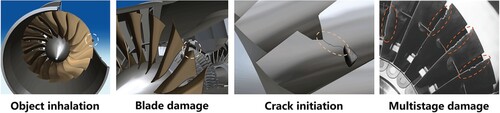
Fatigue fracture caused by damage is a long-term problem to be faced during the whole service life of an aero-engine. Fan and compressor blades are key components of aero engines. Their fatigue performance is closely related to damages encountered during engine service life thereby becoming, an important factor causing aircraft “heart disease” [Citation1]. During the long service life of an aero-engine that operates in harsh environments (including Gobi, desert, ocean, etc.), the fan and compressor may inhale hard objects such as sand, gravel, screw, nut, etc., which cause severe damage to blades named Foreign Object Damage (FOD) [Citation2–4], as shown in Figure . Titanium alloy is very sensitive to defects and is prone to high-frequency fatigue fracture under the condition of air induced vibration. A crack of 0.1 mm can reduce the fatigue strength of the blade by about half [Citation5,Citation6]. Compressor blades will withstand an in-take air flow rate of roughly 1.2 tons/sec, a temperature of up to 540 °C, and a pressure of 600 psi during service [Citation7]. Under these service conditions, extremely high centrifugal loads and vibrations caused by aerodynamic loads develop on the titanium alloy compressor blades. During flight, damaged blades are very easy to induce fatigue crack initiation and propagation under the combined action of low cycle fatigue (LCF) loads and high cycle fatigue (HCF) loads, and then lead to fracture failure [Citation8] or even non-containment accident [Citation9,Citation10], seriously threatening flight safety [Citation11]. According to statistics, in the 20 years from 1996 to 2016, China’s major civil aviation companies recorded a total of 1765 engine FOD failures, involving 16 well-known engine models such as CFM56 series, Trent700, and V2500 [Citation12], causing huge economic losses. What’s more, there are special requirements on military aviation engine models for special environmental conditions such as Gobi low altitude penetration. Thus the FOD failures of the fan and compressor blades of such engines have been more serious than those of civil ones.
Figure 1. FOD failure of aero-engine fan blades.
The mainstream engineering solutions for the deterioration of fatigue performance of fan and compressor blades due to FOD are divided into two types of processes: strengthening and repairing. Strengthening processes are usually carried out before engine service, including surface treatments by laser shock peening (LSP) [Citation13,Citation14] and shot peening (SP) [Citation15,Citation16], to improve the fatigue performance of fan and compressor blades. Repairing processes are often conducted after service, including processes of grinding, welding, and additive manufacturing (AM) [Citation17,Citation18], aiming to improve surface conditions of damaged blades and reconstruct geometric dimensions, to restore the fatigue performance of the blades. As the fourth-generation fighters adopt integral titanium alloy blisk design in engine fans and low-pressure (LP) compressor blades (very different from former tenon-mortise assembly of blades and disk in material and constructure), the crack or fracture on a single blade would cause invalidation of the whole blisk, which not only seriously affect engine utilization, but also bring huge economic burden since expensive titanium alloy blisk has a long and complex manufacturing cycle. Conventional grinding and repairing methods could not solve problems such as angle drop, bulge, large gap, and large deformation occurring on titanium blisk blades, AM is used more widely in engine blade repair as the mechanical manufacturing concept and technology improved, mitigating the difficulties in the repair of damaged blades of the fourth-generation fighter engines.
AM repair can effectively restore the “shape” of the damaged components, but defects such as solidification cracking and microstructural changes formed during the repair process [Citation19] would result in significantly worse fatigue performance as compared to the original ones, which is called “same shape with different performance” [Citation20–22]. AM repair for titanium alloy stators of aero-engines has been partially realized, with the results of enhanced tensile strength and yield limit but worse plasticity [Citation23,Citation24] and insufficient fatigue strength [Citation25,Citation26] due to residual tensile stress, phase transformation in the repaired zone and heat affected zone (HAZ), and manufacturing defects. Therefore, AM repair has not been widely used on rotating parts of aero engines. Driven by the above problems, the aero-engine industry has been exploring technologies to improve the fatigue performance of AM repaired blades, and research on restoring fatigue properties of titanium alloy parts after AM repair is carried out in recent years from the aspects of heat treatment [Citation27,Citation28] and surface strengthening [Citation29–31].
The working environment of an aero-engine is harsh. In contrast, the safe operation of an aero-engine is directly related to the life and property of everybody on board. Thus, safety becomes the core issue when fan or compressor blades are mounted back to service after AM repair. Tan et al. [Citation32] reviewed the processing window, microstructure, material properties, and performance envelops of aero-engine materials manufactured by laser additive manufacturing (LAM). Their work covered the three most widely used aero-engine materials, namely the advanced high-strength steels, nickel-based superalloys, and titanium-based alloys, but neglected practical issues about the operational environment of engineering structural components manufactured by LAM. Blakey-Milner and his colleagues [Citation33] conducted a comprehensive review on the issue of metal AM in the aerospace industry. Their work focused more on the commercial benefits and industrial application of AM components and structures, demonstrating numerous successful examples of metal AM in aerospace applications. They summarized many open research issues in the aerospace AM industry, including part certification, unique quality control requirements, post-processing challenges, potential reduced fatigue properties, and supply chain maturity issues required to produce functional components, and proposed prospects for future research and technological development in this field. But they did not discuss the specific issue of repairing aero-engine blades. Kanishka et al. [Citation34] produced a comprehensive analysis of the foundational principles and prospective applications of AM restoration and repair. Their review focused more on reverse engineering, process parameters, and commercial applications rather than mechanical properties, emphasizing the application of AM technology in the repair process of different industrial products.
In addition to commercial benefits and engineering applications, there are also many comprehensive reviews on the fatigue properties of AM structural components. Liu et al. [Citation35] introduced the latest research results about the fatigue properties of AM superalloys and titanium alloys. The LCF, HCF behaviors, and fatigue crack propagation (FCG) processes of these alloys under multi-field coupling and general testing conditions were compared. The effects of defects, microstructures, AM processes, post-treatments, and heat treatments on fatigue properties were highlighted. They also discussed the relevant fatigue mechanical models and the manufacturing defects and other parameters that should be emphasized in the models. Foti and collaborators [Citation36] presented an overview of multiaxial fatigue in AM metallic components, provided insights into crack initiation sites and growth orientations, and related them to the fatigue failure mechanisms in these components. In addition, the development history of fracture mechanics models considering original defects was discussed, and the principal life prediction methodologies applied for the fatigue damage assessment of AM components under multiaxial fatigue loading were presented, with prediction accuracies of different models.
Although there are extensive reviews on the impact of AM repair process on fatigue performance [Citation37–40] as well as the fatigue problems of titanium alloy components after AM repair [Citation41–44], no comprehensive investigation has been conducted on the application of AM repair on titanium alloy blades, or the latest progress in fatigue performance evaluation methods used for AM repaired titanium alloy parts. The purpose of this paper is to present a strict and special investigation on fatigue problems of AM repaired titanium alloy parts (especially aero-engine blades), to summarize an integral status of AM repair at present and to give suggestions on future research directions. Therefore, this paper makes an in-depth review of AM repair of titanium alloy parts from the aspects of technology development, fatigue performance evaluation methods, factors influencing fatigue properties, etc., aiming especially at the major demand for AM repair for damaged aero-engine blades. Methods widely used to repair aero-engine blades are described in the paper, key influencing factors of AM repair on the fatigue performance of titanium alloy blades are analyzed, fatigue evaluations on AM repaired titanium alloy parts are summarized, and research trends are forecasted. The purpose of this review is to provide the latest and complete information about AM repair for titanium alloy blades and promote the research and application of this technology in the aero-engine field.
2. Present status of aero-engine blades’ manufacturing and repair
The titanium alloy fan and compressor blades require sufficient static strength reserve and fatigue strength reserve under the combined action of vibration stress and steady-state stress in service conditions. The static strength reserve requires that the blade’s tensile stress and bending stress be controlled within the allowable range of materials, capable of continuously carrying out work without failure. The fatigue strength reserve requires that the transient value of the maximum vibration stress of the blade should be ≤60% of the HCF limit of the blade (i.e. the HCF strength reserve ≥1.67). The titanium alloy’s fatigue limit requires that the target number of cycles reach 109. However, considering the test cost of conditioned fatigue limit, it is usually reduced to 108 cycles in practical engineering applications. In cases where HCF limit higher than 3 × 10⁷ is not available, the HCF limit for 108 cycles can be temporarily calculated based on the 3 × 10⁷ cycle test results and the SN curve fitting equation [Citation3,Citation45]. This strict blade generic performance requirement poses a challenge to the manufacturing and repair process of blades.
2.1. Manufacturing of blades
With the growth of the aviation industry, there has been a heightened demand for improved engine performance, which in turn necessitates better fan/compressor blades. Traditional casting, cutting and other methods are often inefficient when dealing with large integrated blisks or turbine blades with film cooling holes, and achieving precise dimensional accuracy can be challenging, leading to significant material waste. In recent years, AM technology has garnered widespread attention due to its ability to offer new solutions for blade preparation in the field of aeroengines.
Based on the 3D model, AM process could form a metal part with fully dense and high performance in one step by in-situ metallurgy, rapid solidification and layer-by-layer stacking methods. In other words, AM presents an easier way to manufacture metal parts with complicated structures and realizes the well-known ‘free manufacturing’ [Citation46]. In Standard F2792 [Citation47] of the American Society for Testing & Materials (ASTM), AM process is divided according to their different additive processes into two types: direct energy deposition (DED) technology and powder bed fusion (PBF) technology.
Currently, there are several powder-based AM technologies for metal parts. Laser metal deposition (LMD), laser cladding deposition (LCD), and laser engineered net shaping (LENS) belong to DED. Selective laser melting (SLM), selective electron beam melting (SEBM), and selective laser sintering (SLS) belong to PBF [Citation34]. Among them, LMD, SLM, and SEBM are widely used for additive manufacturing of components in the aerospace industry [Citation48,Citation49]. If divided according to the energy source used in AM process, both LMD and SLM use a laser as an energy source, while SEBM uses an ultra-high kinetic electron beam which is more effective and easily absorbed with larger action depth and smaller metal reflection compared to laser. Thus, SEBM has better forming efficiency than SLM. If divided according to material feeding modes in AM process, LMD is powder feeding type, and SLM and SEBM are powder spreading type. The powder spreading mode is more suitable for small and complex fine structure manufacturing since it is more stable and air controllable (or vacuum), and so the material powder can be self-supporting with high spatial accessibility during the manufacturing process. All the above AM processes have their own scope of application in metal part manufacturing due to their respective characteristics. Compared with LMD, the laser/electron beam size used by SLM or SEBM is smaller, and the forming accuracy of SLM and SEBM is higher, as shown in Figure . Zhao et al. [Citation48] summarized the differences in technical parameters of the three commonly used titanium alloy AM processes, as shown in Table .
Figure 2. Comparison of three AM processes used for metal manufacturing [Citation50–52].
![Figure 2. Comparison of three AM processes used for metal manufacturing [Citation50–52].](/cms/asset/ccc2fa80-fc5a-4675-8086-d9b7aee88ece/tmrl_a_2275599_f0002_oc.jpg)
Table 1. Comparison of three AM processes used for TC4 titanium alloy [Citation48].
Based on the above analysis, the SLM process is suitable to manufacture small titanium alloy parts with porous material and complex geometry, and could present the best surface quality. But it has very high requirements on material powder particles and a rather low forming efficiency. The forming capacity of the SEBM process lies between LMD and SLM, and the SEBM processed parts have a smaller size compared to LMD processed ones. These three AM processes have been utilized for the manufacturing of aero-engine blades. However, when it comes to repairing damaged blades, the powder spreading mode, despite its advantages in stability and precision, faces challenges in accurately applying powder on damaged blades due to their varying damaged positions and dimensions. As a result, the presently adopted repair process for aero-engine blades and blisk is the powder feeding LMD [Citation53]. Nevertheless, further process optimization and validation are necessary for the successful application of PBF in blade repair.
The application of AM technology in the field of engine blades has primarily focused on turbine blades. Siemens, for instance, has developed and tested functional prototypes of gas turbine blades by utilizing AM techniques. They have also successfully printed turbine blades of a 13-megawatt SGT-400-type industrial gas turbine using DMLS (direct Metal Laser Sintering) technology and completed full load testing [Citation54]. The use of AM technology has significantly reduced the development and validation time for these components. The Boeing 777X and Comac C919 are powered by GE’s massive GE9X engine, which features EBM-printed TiAl low-pressure turbine blades [Citation55]. These blades were manufactured by melting TiAl powder using an Arcam EBM machine and builting it into 40 cm long blades, resulting in a weight reduction of 50% compared to traditional nickel-based alloy blades. The successful commercial applications of AM turbine blades demonstrate their strong market competitiveness. Furthermore, AM technology also plays a crucial role in the repair of aviation industry components.
2.2. Repairing of blades
Several methods such as mechanical grinding, welding, and AM are used for the repair of fan and compressor blades [Citation18]. For repaired blades, their structural strength performance requirements must be met before being put into service. The higher the recovery degree of the repaired blade’s mechanical and fatigue properties, the easier it is to meet its structural strength performance requirements of the blades. It is generally agreed that grinding could be used for light damage or damaged area which bears lower working stress since grinding could reduce the stress concentration factor of the damaged area and restore fatigue resistance. However, for large damage or damaged area bearing large working stress, for example, blade tip drop, large blade body gap, large deformation, blade root gap, etc., welding or AM repair is usually selected to restore the geometric shape.
Mechanical polishing is a common method used to repair damaged fan or compressor blades of aero-engines. The typical mechanical process generally includes cutting, grinding, and polishing, to locally remove the materials in the damaged area of blades, and to form a gap with specific dimensional characteristics (width/depth ratio), thus reducing the stress concentration factor at the damaged location, and restore the fatigue performance to a certain extent. After the mechanical process, the repaired blades could meet the operation requirements. The mechanical repair process has been used on both military and civil aero-engines for many years because its principle is simple and its operation controllable. In the operation and maintenance manuals of main engine products in service (such as LEAP-1A and CFM56), the requirements for mechanical repair are stipulated, and strict standards and specifications are given for fan and compressor blades’ grinding and repair. For example, the division of repair areas and specification of repair dimensions are shown in Figure .
Figure 3. Maintenance specifications on aero-engine blades. (a) CFM-LEAP-1A engine fan rotor blade maintenance [Citation56]; (b) CFM56-3 engine fan rotor blade maintenance [Citation57]; (c) CFM56-7 engine fan rotor blade maintenance [Citation58].
![Figure 3. Maintenance specifications on aero-engine blades. (a) CFM-LEAP-1A engine fan rotor blade maintenance [Citation56]; (b) CFM56-3 engine fan rotor blade maintenance [Citation57]; (c) CFM56-7 engine fan rotor blade maintenance [Citation58].](/cms/asset/d22d8645-6629-4c83-af74-bf1a9d6bc12a/tmrl_a_2275599_f0003_oc.jpg)
However, mechanical grinding repair is a material reduction process that limits the recovery of fatigue performance in the damaged area. It is good enough for small-size blade damage and damage at low stress areas, but it could not solve the problem of large-size blade damage or damage at high stress areas. In addition, the grinding repair only reduces the stress concentration factor in the damaged area but the damage remains, which has an inevitable impact on the aerodynamic performance of the engine.
Repairing based on welding is a widely used and economically beneficial technology for aero-engine blades [Citation59]. Welding technology has successfully been applied to repair engines’ compressor and turbine blades made of various materials such as titanium alloy, aluminum alloy, superalloy, and single crystal. For example, Zhang et al. [Citation59] studied a turbine blade which was made of DS GTD111 material and repaired by arcwelding and discussed the failure issues of the repaired blade. Sayilgan et al. [Citation60] used powder surfacing to repair the tip wear and cracks of a Ni-based single-crystal turbine blade. They successfully restored the initial geometry of the blade and created a single-crystal microstructure. Patriarca et al. [Citation61] studied the mechanical behavior characteristics of Alloy625 wire-arc deposition alloy under LCF loads, discussed the LCF crack propagation characteristics, and provided guidance for damage tolerance design of repaired components.
Sometimes, it is difficult to define between welding and AM repair processes. Sikan et al. [Citation7] studied the repair of a Ti-8Al-1V-1Mo compressor blade using electron beam wire-feed technology, which can also be considered as a use of welding technology. However, welding repairs face challenges such as uncontrollable geometry shape [Citation62,Citation63], nonuniform mechanical properties in the welded area [Citation64,Citation65], and safety concerns for the repaired blades.
In order to solve the damage problems that mechanical grinding and welding could not repair, AM has been introduced into the field of aero-engine repair. The conventional repair scheme for damaged titanium alloy compressor blades includes several sequential operations, which are, inspecting and removing the FOD, preparing and sending powder to damaged areas for melting and depositing, namely LCD, stress relief (SR), and machine the repaired components [Citation66]. After the material powder is shaped in forms, both the geometric dimensions and mechanical properties of the damaged blade are restored [Citation67]. With the development of titanium alloy AM technology, many research works have been conducted on AM repair for aero-engine fan and compressor blades. Some achievements have been applied in industries, partially solving the blade repair problems caused by in-service damages [Citation68,Citation69]. A variety of blade repair processes and optimization methods have been put forward to restore the geometry and dimensions of damaged blades.
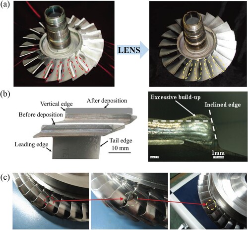
The laser AM repair technology applied for aero-engine fan and compressor blades and blisks is rather mature in the United States and Germany. The Sandia National Laboratory of the U.S. developed LMD technology in the 1990s [Citation70]. Optomec Design Company popularized the LMD process and then developed LENS technology in cooperation with the Laboratory [Citation71]. The LENS process has been used to repair worn parts of U.S. Navy T700 engines (as shown in Figure (a) [Citation33]), realizing rapid and low-cost remanufacturing of damaged aero-engine parts.
Figure 4. LMD repair technology used for aero-engine blades. (a) Titanium alloy blisk blade repaired by LENS process of Optomec Design Company; (b) Nickel-base turbine blade knife-edges repaired by Fraunhofer Laser Technology Association; (c) Titanium alloy blisk blades repaired by Northwestern Polytechnic University.
What’s more, H&R Technology Company of the U.S. has repaired the blisk of the T700 engine with LCD technology. Huffman Company also used LCD technology to repair both nickel base superalloy and titanium alloy aero-engine blades. The “Mobile Repair Station” developed by the U.S. military also used LCD technology to realize rapid processing and remanufacturing of metal parts. It has already entered service in U.S. Navy and Army, and played an important role in the Afghan battlefield.
A lot of research have been carried out on laser repair technology for aero-engine blisk by German institutes. Singapore Institute of Manufacturing Technology and German Fraunhofer Laser Technology Association [Citation72] conducted laser AM repair on nickel-base turbine blade knife-edges according to a pre-designed technological path which applied multi-layer laser deposition, and successfully restored the dimensions and mechanical properties of blades, as shown in Figure (b). The LMD repair technology [Citation73] developed cooperatively by Laser Zentrum Hannover e.V. and Leibniz University Hannover can be used in depositing and remelting single-crystal structures on substrates of the nickel-based superalloys CMSX-4 and turbine blade tips of PWA 1426, restoring original geometric dimensions. The Fraunhofer Institute of Laser Technology [Citation74] in Germany developed a special nozzle to carry out LCD repair for titanium alloy blades which needs no atmosphere protection chamber, realizing local repair of the leading edge of Ti-17 blisk blades. Furthermore, Germany has launched the “Integrative Production Technology for Energy-efficient Turbo-engine Project (TurPro)” in recent years. The first research of the Project is AM technology which aims to achieve local repair of the edge and tip of blisk blades by LAM and then strives for direct replacement of damaged blades or even direct manufacture of blisk through the combination of initial design, manufacture process, and LAM technology.
In addition, explorative research on AM repair for aero-engine blades have been carried out in universities as well as enterprises in China. Professor Huang Weidong’s team from Northwestern Polytechnic University conducted LMD repair tests on damaged blades and blisks made of TC4[Citation75], TC11 [Citation76], and TC17 [Citation77] titanium alloys or GH4169 [Citation78,Citation79] and K418 [Citation80] superalloys. They studied the microstructure evolution rules and performance control methods for small laser molten pool solidification of different materials, and characterized the microstructure and hardness distribution rules in different areas (repaired zone, HAZ, and forged substrate zone) of LMD repaired titanium alloy parts. The performance of repaired parts has been evaluated, and several batches of repaired parts have entered service, as shown in Figure (c). The research on LMD technology by Professor Wang Huaming’s team of Beihang University focuses on the application in large-scale main load-bearing titanium alloy structural parts [Citation81] and high-performance material gradient structural parts [Citation82] of aircraft, as well as directional solidification of refractory metal materials [Citation83]. They have formulated a complete set of technical specifications on LMD technology used for aircraft titanium alloy structural parts.
Some specific achievements in AM repairing titanium alloy blades are listed below. Paydas et al. [Citation84] investigated the mechanical properties of repaired samples by LCD processes on a Ti-6Al-4V substrate. The deposition regions showed higher hardness and tensile strength. LCD can be considered as an adequate repair technology for restoring the mechanical properties of Ti-6Al-4V alloy. Shrestha et al. [Citation85] used two different Ti-6Al-4V feedstocks (metal powder and wire) to repair the Ti-6Al-4V alloy substrate through DED processes. Subsequently, dog bone specimens for fatigue testing were machined with a bond line at the center of the specimen gauge. DED repaired samples could obtain mechanical properties comparable to those of conventional Ti-6Al-4V alloy, but exhibited a decrease in fatigue performance, which was more obvious in the samples repaired by metal wire. They also evaluated the fracture toughness and fatigue crack growth rate of the two types of repaired samples [Citation86,Citation87]. The results showed that the fracture toughness of the repaired samples was slightly lower than that of annealed Ti-6Al-4V specimens, and the fatigue crack growth rate was slightly higher than that of conventional specimens.
There are relatively few cases of AM repair research for actual aero-engine blades. Sikan et al. [Citation7] discussed the surface residual stress distribution of the Ti-8Al-1V-1Mo blade after 20,000 h of in-service thermo-mechanical loading cycles. The residual stresses on the blade basin side are mainly compressive, with magnitudes ranging from −300 to −500 MPa, and no obvious tensile region can be observed. The compressive residual stresses are distributed in a gradient from the periphery to the center. The measurements on the blade’s backside indicate higher compressive residual stresses (−600 to −700 MPa) around the tip and the leading edge, while the magnitudes are lower on the tail edge. Tensile residual stresses (200 MPa) are apparent near the root section of the blade tail edge. A gradient distribution in residual stresses is noticeable along the diagonal direction from the tip of the leading edge to the root of the tail edge. This stress state gradually evolved from the initial residual stress introduced by surface strengthening (such as SP, LSP) during the service operation. The complex local stress distributions of compressor blades can have adverse effects on the AM repair process, causing local deformation and large residual stresses in the repair region. This is a huge challenge for the repair of aero-engine blades.
Pre-processing and post-processing are critical for pushing AM repair technology to Maintenance, Repair & Operations (MRO) applications. Currently, almost all studies on AM repaired titanium alloy blades are carried out by directly depositing repair layers on substrate samples [Citation85–88] or by prefabricating grooves on substrate samples for depositing repair layers [Citation84,Citation89,Citation90]. In research on the AM repair of substrate, the pre-processing methods generally involve sandpaper polishing and alcohol cleaning as well. During the actual maintenance process, it is essential to comprehensively consider parameters such as damage location, size, and morphology when performing AM repair on damaged blades. Firstly, a repair plan should be developed based on the damage situation, and the geometric parameters of the repair area should be determined. Then, an appropriate mechanical processing method must be selected to locally remove the damaged material and obtain the desired geometric morphology. Finally, the area to be repaired should be polished and cleaned to ensure that its surface condition meets the repair requirements [Citation66,Citation67].
After completing the repair, post-processing methods such as Solution treatment & aging (STA), Broken-up structure (BUS), Hot isostatic pressing (HIP), Machining and polishing (M&P), SR, etc. are applied to AM repaired blades [Citation91–96]. These post-processing methods mainly affect the microstructure, defects, surface roughness, and residual stress of AM components through heat treatment and mechanical processing, in order to obtain better physical and mechanical properties. The specific influences caused by these post-processing methods are described in Tables in Section 3 of this review.
Table 2. Effect of microstructure on HCF strength of AM manufactured titanium alloy.
Table 3. Effect of manufacturing defects on HCF strength of AM processed titanium alloy.
Table 4. Effect of surface roughness on HCF strength of AM processed titanium alloy.
Table 5. Effect of residual stress on HCF strength of AM processed titanium alloy.
However, it is important to note that aero-engine blades repaired in the outfield usually do not have the necessary conditions to perform most of the post-processing. For instance, a suitable heat treatment furnace cannot be easily found in remote locations for blisk due to its large volume. As a result, the fatigue performance of AM repaired blades typically falls short of that of forgings. Therefore, further improvement of the AM repair process is required to enhance the comprehensive performance of the blades in the As-built (AB) state. Ensuring the safe use of aeroengines loaded with AM repaired blades poses a significant challenge, particularly in terms of fatigue evaluation.
Relevant AM processes used to manufacture large titanium alloy structural parts (such as corner boxes and abdominal fin joints), titanium alloy special coatings and high-temperature alloy structural parts are mature enough to satisfy demands. Aero-engine blades work under complex and severe conditions, and bear multiple axial loads. Present LMD repaired aero-engine blades have problems such as insufficient dimensional accuracy and stability, large surface roughness, and deteriorated fatigue performance. It is difficult to accurately evaluate the fatigue performance of LMD repaired blades since the evolutionary law of stress and microstructure is not clear and the fatigue failure mechanism under the working state is difficult to master. These directly limit the safe use of AM repaired blades. Recent research has paid more attention to the fatigue performance improvement of LCD structural parts from the perspectives of the manufacturing process, microstructure evolution, residual stress, additive defects, and so on. However, due to experimental conditions, most studies were conducted on AM standard specimens, which can guide the performance of AM repaired blades but require further verification in actual structural components. Furthermore, no systematic fatigue assessment methods and criteria have been established for LMD repaired titanium alloy structural parts, and uncertain risks still exist in engineering application. Therefore, future AM repair research for titanium alloy blades should focus on establishing comprehensive fatigue assessment methods and criteria for AM repaired structural parts.
3. Effect of AM on fatigue performance of titanium alloy blade
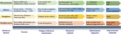
Extensive research results show that the effect of AM process on titanium alloy fatigue performance mainly depends on microstructure, manufacturing defects, surface roughness, and residual stress [Citation49,Citation122,Citation123]. The four factors play different roles (mostly negative) in affecting the fatigue performance of AM repaired titanium alloy, as shown in Figure .
Figure 5. Influencing factors of AM on fatigue properties of titanium alloy. Notes: LOF – Lack of fusion, EVS – Extreme Value Statistics, PD – Probabilistic distribution, DAN – Double Annealing.
3.1. Microstructure
LAM manufactured parts are certain to have different microstructures caused by rapid cooling and solidification of alloy within the molten pool since the LAM process is accompanied by rapid heating and rapid cooling. This is similar to rapid quenching in the heat treatment process. AM process with a single layer or few layers usually leads to the generation of a fine metastable phase, while multi-layer cladding manufacturing will seriously affect the microstructure of AM processed parts since the repeated heating and cooling of the deposited layer brings about a complex thermal cycle. In addition, repeated multi-layer AM process presents a unique mesostructure influenced mainly by filler spacing, powder layer thickness, and scanning mode. These complex characteristics across the micro- and meso-scales determine that the fatigue dispersion of AM processed titanium alloy is much more complex than that of forged or cast alloys.
For titanium alloy, the rapid heating and cooling cycle of AM process leads to fine microstructure consisting of metastable martensite α′ phase within prior β grain (PBG), most of which could be observed as obviously layered microstructure [Citation97]. Eylon et al. [Citation91,Citation92] studied the effect of microstructure on the properties of powder metallurgy Ti-6Al-4V alloy. They used BUS or Thermochemical treatment (TCT) to obtain a fine α flake structure. The result is that the grain size of α reduces by an order of magnitude compared with the reference, and the cluster structure is removed. The tensile strength and fatigue strength of Ti-6Al-4V alloy are significantly improved by adjusting the microstructure, and the fatigue strength of TCT processed samples is the highest. Liu et al. [Citation124]repaired Ti-6Al-4V alloy parts by DED and EBM (Electron Beam Melting) processes and obtained fatigue limit improvement in the repaired area at the cost of a lower crack growth threshold. This is due to the high-density dislocations of α′ Martensitic phase generated during the AM process. That is, the significant dislocation strengthening effect improves fatigue performance [Citation124].
Hagiwara et al. [Citation93] also studied the effect of different microstructure characteristics on the fatigue strength of Ti-6Al-4V alloy. They used several heat treatments including HIP, BUS, and STA to refine and regulate the microstructure of fully densified materials, and obtained a bimodal lamellar structure. In addition, they applied cold rolling before HIP to regulate the columnar microstructure into an equiaxed shape. This kind of bimodal microstructure has the highest fatigue strength with better performance than most cast titanium alloys. Crack generation and propagation in the whole structural part could be prevented by refinement of the microstructure whose effect is similar to a single crystal. Joshi et al. [Citation125] also validated the excellent fatigue properties of Ti-6Al-4V alloy with bimodal microstructure. They used a thermos-mechanical deformation process to heat treat the Ti-6Al-4V alloy to change the rolled network structure into a bimodal microstructure. This change increased the fatigue strength of the sample from 500 to 550 MPa.
Xu et al. [Citation111] annealed the SLM processed Ti-6Al-4V alloy sample at a low temperature to decompose the martensitic phase formed in manufacturing. They obtained very fine α Lath grains which improved both tensile strength and fatigue properties simultaneously. Wirth and his collaborators [Citation126] carried out fatigue performance tests on powder metallurgy Ti-6Al-4V alloy under different heat-treating conditions and validated that α+β phase structure with fine lenticular grains had the best fatigue strength. Cao et al. [Citation127] studied the effect of thermo-mechanical deformation on the fatigue properties of AM processed Ti-6Al-4V alloy through the hot-rolling treatment of α+β phase. It is validated that thermo-mechanical deformation treatment under β phase transition temperature reduces the porosity, transforms the layered structure into elongated or lenticular grains along the rolling direction, and induces texture. Such treatment improves the fatigue strength of the structural part from 325 MPa at sintered state to 400–450 MPa (according to the degree of rolling and deformation). Both microstructure and porosity affect the fatigue performance of titanium alloy, but they show different effects under different stress levels, which will be described in Section 3.2.
The importance of microstructure regulation on fatigue properties of titanium alloys is obvious, especially for α+β phase and β phase titanium alloys which need microstructure optimization to obtain better fatigue strength [Citation41]. Based on continuous exploration in post-AM treatment, a Laser Powder Bed Fusion (LPBF) process used for Ti-6Al-4V alloy is presented to stably obtain α+β phase microstructure. The steps of the DAN process are as follows: (1) 910° annealing (AN), (2) water quenching, (3) AN again at 750°, (4) air cooling (AC). Thus a bimodal microstructure consisting of broken equiaxed primordial α grains within a lamellar secondary α+β matrix can be obtained [Citation128–130]. Previous work validated that such bimodal microstructure can well balance the ductility and strength of titanium alloy, improve the near threshold fatigue crack growth resistance effectively, and in turn, improve the fatigue performance of the material. The HCF strength of AM manufactured titanium alloy influenced by different microstructures are summarized in Table .
3.2. AM defects
There is a difficult balance between laser energy input and metal powder melting during the LAM process, which leads to inevitable manufacturing defects in AM processed structural parts. Excess input energy seriously affects the stability of the molten pool, resulting in the splashing or evaporation of molten metal droplets which cause pore defects. Spherical or ellipsoidal pores with diameters of about 1–100µm usually present a random distribution in the material. On the other hand, insufficient input energy leads to LOF defects since metal powder could not be completely melted. The LOF defects are larger in size than pores, and usually show irregular wedges or bands with tips, as shown in Figure (a, b).
Figure 6. Defects on LAM processed TC17 samples. (a) and (b) Pores and LOFs observed by CT and OM; (c) Fatigue fracture of tensile specimen caused by pores; (d) Fatigue fracture of blade leading edge caused by LOF.
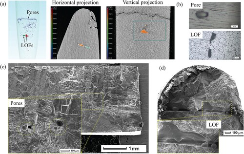
In the Standard E3166 [Citation131] issued by ASTM, AM defects are described as pores (which may be isolated or located in clusters close to the surface or embedded in deep layers), LOF (which may be between layers or across layers), start and stop errors, inclusions, layering, under melting or over melting. A large number of studies have shown that under the action of cyclic load, AM defects usually become the starting points of crack initiation, as shown in Figure (c, d) which has a significant adverse effect on the fatigue performance of structural parts [Citation98,Citation106,Citation115,Citation132–135]. Present research mainly focused on the relationship between the size and location of defects as well as the resulting fatigue behavior [Citation136]. Therefore, the first work to be done should be the effective observation and characterization of AM defects.
Computer tomography (CT) is an effective observation and testing method for AM defects in the industry. The core test parameter of CT technology is resolution, which is related to the size and number of detectors, the size of X-ray focus, and the size of the objects that affect the distance between the X-ray source, detection object, and detector. The typical commercial CT equipment used in the industry at present has a high resolution for pores with diameters more than 10µm, while for defects whose sizes are less than this value, the judgment becomes inaccurate [Citation137,Citation138]. To further improve the resolution of CT equipment, the X-ray input energy has to be increased and the scanning time greatly extended under the condition of maintaining the original field of view and signal-to-noise ratio. Thus the test cost is significantly increased [Citation139]. As a global defect analysis method for AM processed parts, CT technology is difficult to accurately measure the shape, location, and characteristics of defects due to the limitation of resolution. However, conventional destructive testing methods such as Scanning Electron Microscope (SEM) could realize microscopic observation on the surface and sections of AM processed parts. SEM provides more refined local characteristics of defects, but it cannot carry out the global analysis. Therefore, the optimal solution is to combine the two methods to obtain the best analysis [Citation140].
Pegues et al. [Citation140] combined the above two methods to obtain 3D global (CT) and 2D local (SEM) results for AM defects of a tubular LPBF Ti-6Al-4V alloy sample. The 3D result is characterized by a high-resolution CT which made a global test on a 10 mm long sample. It showed the locations, shapes, sizes, and overall distribution of a large number of defects. The 2D result is characterized by a high-power digital microscope which collected images from the polished surface of the sample. It could provide precise observation on characteristic defects, and so it is used to differentiate types of defects, and to analysis conditions on which defects generate.
Based on these observation conditions, the parametric characterization of AM defects is studied. Sanaei et al. [Citation141] characterized four key features of AM defects, namely, Feret’s diameter and area that reflect the size of defects, roundness, and aspect ratio that reflect the shape of defects. The parameters defined in 2D observation conditions are as follows: (1) the Feret’s diameter of defect is the longest distance between any two points along the selection boundary; (2) the area of defect is the area of each defect within the external selected boundary; (3) the roundness of defect is a measure of irregularity of defect shape calculated by 4π (area/perimeter2) within a range of between 0 and 1; and (4) the aspect ratio of defect is a measure of elongation of each defect calculated by the ratio of a fitting ellipse to the longest diameter of defect, also within a range of between 0 and 1. A lower aspect ratio indicates a longer defect. The characterization method for the above parameters under 3D observation conditions is also proposed based on CT technology [Citation142].
Molaei and his collaborators [Citation94] researched the cyclic deformation and multiaxial fatigue behaviors (axial, torsional, and 90° axial torsion combined in-phase and out-of-phase) of PBF Ti-6Al-4V alloy thin-walled tubular specimens. The influence of parametric differences of AM equipment on the size and number of defects has been investigated, as well as the resulting failure mechanisms and fatigue properties. It is found that the failure mechanism of AM samples was tensile failure after long-time operation, which showed that the fatigue behavior of the sample was mainly affected by manufacturing defects under HCF load. After HIP treatment, the fatigue life of the sample under the HCF condition was significantly improved, showing similar fatigue behavior to that of forged materials under different loads. This is because the HIP treatment made the defects close and shrink. However, the remaining LOF defects in the specimen are still the main source of crack initiation. In addition, the fatigue life of vertical and diagonal (45°) constructed specimens has been tested, and the latter showed a slightly longer fatigue life under torsional load and a shorter fatigue life under axial load. This could be attributed to the vertical relationship between the AM construction direction and the LOF defect growing direction.
A reasonable explanation has already been given for the fatigue initiation mechanism of metal materials. That is, local plastic deformation leads to the formation of low-energy subgrain dislocation under a saturated state, and eventually fatigue crack initiates when the dislocation develops into irreversible plastic deformation and results in cyclic damage [Citation143,Citation144]. As for AM processed metal materials, the stress concentration effect at the manufacturing defects promotes the generation of local plastic deformation under HCF load, and then becomes the source of fatigue crack initiation regardless of the macro mechanical response of the part being elastic deformation or not [Citation145,Citation146]. The plastic deformation at the defect is mainly affected by the size (diameter and area) and shape (roundness and aspect ratio) of the defect, as well as nearby microstructure characteristics (phase composition, grain size, and crystal orientation). Manufacturing defects have little influence on the FCG of AM processed titanium alloy from the perspective of crack propagation. Leuders et al. [Citation96] validated that local stress concentration caused by defects does not provide any additional driving for the FCG behavior of LPBF Ti-6Al-4V alloy. This conclusion is consistent with Poulin et al. [Citation147] on the FCG behavior of LPBF Inconel 625 alloy. It is found that the Fatigue Crack Propagation Rate (FCGR) hardly changed but the fracture toughness was significantly affected in Inconel 625 alloy with different porosity levels (0.1%, 0.3% and 2.1%).
It is generally believed that larger defects are more likely to cause failure than smaller defects, and the largest defect directly affects the fatigue strength of the part [Citation148]. AM processed titanium alloy usually contains a large number of small-size defects, which brings a huge workload to characterize each defect. In order to solve this problem, PD distribution models of various defects were developed. Günther and his collaborators [Citation106] proposed a Weibull distribution diagram to evaluate the size of internal crack initiation defects in SLM and EBM materials. They determined the size of crack initiation discontinuity through Murakami’s model [Citation149] based on Weibull distribution, established the relationship between failure probability and average defect size in the defect size PD model, and characterized it by the maximum stress intensity factor (SIF KI,max). The results show that pore defects have smaller KI,max, while LOF defects have the largest KI,max. The size of LOF defects is usually the same as the section spacing [Citation97] and reaches the millimeter level, the average defect size is significantly larger than that of pore defects [Citation106]. LOF defects often show very low roundness and aspect ratio [Citation141,Citation150], which is considered to be the main factor leading to fatigue failure of AM processed titanium alloy. Table summarizes the HCF strength data of AM processed titanium alloys with defects of different sizes.
EVS method is a statistical method commonly used to predict the maximum defect size in AM processed parts. It was first applied in the iron and steel industry to predict the maximum inclusion size in large-volume pure steel through the observation of small-volume inclusions, because the maximum inclusions control the mechanical properties and fatigue behavior of steel [Citation151,Citation152]. Romano and his collaborators [Citation153] proposed a method to predict the distribution of defects in uniform volume AM processed parts without global scanning based on the EVS method. They perform X-ray CT on given volume materials with the same characteristics and then process CT test defects by peak value exceeding the threshold and EVS to determine the distribution of most harmful defects in the material. Finally, they predict the maximum defect in a larger volume through the Largest Extreme Value Distribution (LEVD). On this basis, they also predict the fatigue strength of the part according to the location of extreme defects combined with the Kitagawa-Takahashi diagram. A detailed description of the EVS method is given in Section 4.2.
Some physical models are developed in the prediction of AM defects for the shape of the molten pool and thermal properties of materials. The volumetric energy density (VED) model is one of the mainstream models to predict AM defects. Thijs et al. [Citation154] gave its mathematical definition equation. Gong et al. [Citation108,Citation155] gave the relationship between the VED and the minimum defect size, which can provide process guidance for Ti-6Al-4V parts printed by PBF. Bertoli et al. [Citation156] found the influence of VED change on the trajectory of a single molten pool, thus determining the appropriate numerical range. In addition, there are some less-used AM defect prediction models. Tang [Citation157] superimposed multiple pool geometries obtained by the Rosenthal point source heat transfer model. It was found that these defects were caused by insufficient pool stacking in the transverse or vertical direction, and the density change of AM processed AlSi10Mg sample caused by LOF defects was effectively predicted. King et al. [Citation158] deduced the melting criteria of 316L stainless steel under a moving Gaussian heat source and proposed a normalized enthalpy model, which can accurately predict the melting conditions under keyhole mode. The experimental results show that the melting conditions that meet the criterion display pinhole behavior, and the threshold transition point from conduction-controlled melting mode to pinhole-dominated melting mode can be clearly identified. Therefore, this method could be used to predict the generation and development of pore defects in the manufacturing process.
Sheridan et al. [Citation159] compared the prediction effect of the above three models on the porosity of AM processed parts by tests within a relatively wide range of process parameters. The results show that the shape of the molten pool and the amount of VED absorbed are suitable for LOF prediction, but it is still far from real behavior. The normalized enthalpy model is suitable to predict the porosity of small hole mode in matrix and unit cell geometry, but the threshold must be modified according to different process characteristic parameters to ensure certain accuracy. A method of meshing and combining multiple models is put forward to fully describe the whole process space to predict the size characteristics of porosity in LOF and keyhole modes. Using the least square method, three models of density, diameter, and roundness are constructed according to the tested average data. Each component is regarded as a separate training point, and variance analysis is performed on each model to approximately evaluate the error and its source. On this basis, the aperture regression model is applied for the life prediction framework and the given life prediction diagram shows a more accurate and conservative prediction result.
In summary, research results generally show that LOF defects generated in AM process are the most important factors affecting the fatigue performance of structural parts, so the observation, characterization, and evaluation of defects play an important role in the research of fatigue performance of AM processed parts. The prediction and evaluation of fatigue strength of AM processed parts based on AM defects will be especially described later.
3.3. Surface roughness
When the outer geometry profile of AM processed part has a certain angle with the construction plane or the growing direction, the layer-by-layer printing characteristics of AM process will make the inclined outer surface of the part uneven with the layer thickness as the step height. This phenomenon is called the stair step effect [Citation160], which usually is inevitable for AM processed parts to face surface roughness problems at higher surfaces. Li et al. [Citation161] pointed out that the oxidation and adhesion of partially melted particles on the surface of parts are the most important factors to determine surface quality. That means the optimal surface roughness could be obtained by DED, followed by SLM and EBM, because in the DED process the unused excess powder could be blown away. Li et al. [Citation132] summarized three reasons for the high surface roughness of AM processed parts: (1) stair-step effect related to the increase of additive layers, (2) oxidation and adhesion of molten particles on the outer surface, and (3) surface pores and LOF defects. In any case, high surface roughness results in a serious adverse effect on the fatigue performance of AM processed parts [Citation37].
Wycisk et al. [Citation95] compared the fatigue limit of LAM processed Ti-6Al-4V alloy under AB state and M&P state. The sample at AB state doesn’t experience surface treatment, and the average surface roughness is Ra = 12µm. The sample at M&P state has a significantly reduced surface roughness, Ra = 0.16µm according to the standard of mirror polishing. The test results show that the fatigue limit (σmax) of the LAM net shaping Ti-6Al-4V specimen at 107 cycles is 210 MPa, and the fatigue dispersion is low; the fatigue limit of the M&P sample is 500 MPa, and the fatigue dispersion is high. The results of fracture analysis showed that cracks initiated in many parts of the surface of the AB sample, and the higher surface roughness made the area with obvious concave convex more likely to become the source of fatigue cracks. The fatigue source of M&P specimens is mainly manufacturing defects, so it shows significant dispersion.
Greitemeier and his collaborators [Citation121] studied the fatigue properties of Ti-6Al-4 V alloy samples manufactured by DMLS and EBM and concluded that the HCF performance mainly depends on the surface roughness. The surface roughness of the DMLS sample is Ra = 13µm, Rt = 110µm; while the EBM sample is Ra = 27µm, Rt = 214µm. The fatigue limit of DMLS and EBM specimens at 107 cycles is 200 and 150 MPa respectively. They counted the fatigue test data of DMLS Ti-6Al-4 V samples with different surface roughness obtained by Wycisk et al. [Citation95,Citation162] and Vlcek et al. [Citation163] on different additive manufacturing equipment, and drew S-N curves of different surface roughness. The law between fatigue limit and surface roughness can be judged from the curve, the higher the roughness, the lower the fatigue limit.
When considering the influence of surface roughness on fatigue performance of AM processed parts, researchers usually use some equivalent methods to obtain the key influencing parameters of surface roughness, such as maximum peak valley ratio equivalent [Citation121], stress concentration factor equivalent [Citation164], etc. Greitemeier et al. [Citation121] used the equivalent initial defect size (EIFS) method, combined with Murakami et al. [Citation165]’s work on the correlation between characteristic surface roughness and EIFS, to achieve the equivalent EIFS value to describe the effect of surface roughness based on fracture mechanics method. They deduced EIFS from the S-N curve data of AM processed part, then correlated it with surface roughness obtained from the test, and described the equivalent initial defect geometry by semi-elliptical surface cracks. Furthermore, they successfully predicted the fatigue data of AM processed Ti-6Al-4V alloy based on the linear relationship between EIFS and surface roughness values.
In order to solve the adverse effect of surface roughness on fatigue performance of AM parts, relevant research has been carried out and found that improving surface roughness can significantly improve the HCF strength of titanium alloy [Citation107,Citation108,Citation117]. Bagehorn et al. [Citation120] used four commonly used surface roughness improvement methods to treat LPBF Ti-6Al-4V alloy samples, namely, milling, SP, vibration grinding, and micromachining. The results show that the surface roughness of the sample reduces from Ra = 17.9 µm to Ra = 0.3 µm after milling; the 3 × 10⁷ cycle fatigue strength of the AB sample increased from 300 to 775 MPa after treatment, showing the best effect. The improving effect of SP on surface roughness is limited (Ra = 10.1 µm), and the 3 × 10⁷ cycle fatigue strength increased to 525 MPa. It is mainly because the residual compressive stress field introduced into the surface layer of the specimen improved the fatigue performance. Kumar et al. [Citation98] also validated this conclusion by their fatigue life test on LPBF Ti-6Al-4V alloy after SP. It is worth noting that although HIP is often used as post-treatment for AM parts to eliminate internal defects like pores and could effectively improve the fatigue performance of parts, it could not reduce the surface roughness of parts, so it should be combined with a variety of processes to obtain the best effect. Table shows the HCF strength data of AM processed titanium alloys with different surface roughness after various post-treatments.
3.4. Residual stress
The repeated rapid heating and cooling process on the deposited layer during metal additive manufacturing makes the solidified alloy experience an extremely complex thermal cycle, which not only leads to the unique properties of AB material in microstructure, but also has a significant impact on residual stress. During AM process, expansion wave was generated when the local region was rapidly heated by a high-energy beam (laser/electron beam), but then it was restrained by surrounding materials, resulting in local compressive plastic strain. In the subsequent rapid cooling process, the alloy shrunk, resulting in high tensile stress [Citation166]. Sikan et al. [Citation7] examined the residual stress field of titanium alloy compressor blades whose blade tips were repaired using electron beam wire-feed AM technology. The results showed that the intensity of the compressive residual stress near the interface and HAZ on both the basin and back sides was significantly reduced compared with before repair, and a tensile residual stress area could be observed. This is attributed to the formation and solidification of new stress-free β grains [Citation167]. However, the stress relief is not apparent at the center and root section of the blade far from the repair region.
Under HCF load, the high and uneven residual tensile stress acts as an additional crack driving force, causing the initial stress state to move to a higher stress ratio, which can be understood as the overall translation of the applied load spectrum to the high stress direction. Thus the fatigue life of the structural part is reduced obviously, showing poor fatigue performance [Citation96,Citation104,Citation168]. In order to clarify the rule and mechanism of the influence of residual stress field caused by AM process on the fatigue performance of structural parts, a large number of comparative fatigue tests and near threshold FCG studies have been carried out to describe the principle of the influence of residual stress on the fatigue crack initiation mechanism. Rangaswamy et al. [Citation169] used neutron diffraction and contour method to test the residual stress distribution in LENS AISI 316 stainless steel and Inconel 718 nickel base alloy samples. The results show that the residual stresses in AM processed parts are approximately uniaxial, with high stresses in the growth (z) direction, and very low residual stresses in the (x/y) plane perpendicular to the growth direction. The residual stress in the Z direction measured in the test is compressive stress, with a value close to 400 MPa. Compressive stress is beneficial in resisting fatigue cracks. However, the residual stress in the Z direction near the surface of the specimen is tensile stress, with a value of up to 200 MPa. This means that although the residual compressive stress in the center of Z direction of the AM processed part can reduce the applied tensile load, the residual tensile stress near the surface raises the applied tensile load, resulting in a larger load borne by the surface, and the fatigue crack is more prone to sprout.
The influence of residual stress on the FCG stage is more significant. The research of Leuders et al. [Citation96] shows that the material behavior is particularly affected by the internal stress in the subsequent stage of crack propagation. The fatigue life of SLM Ti-6Al-4V alloy was tested under the condition of stress ratio R = −1 and the maximum stress σmax = 600 MPa. It was found that the fatigue life of the AB sample was 27,000 cycles, and it increases to 93,000 cycles after 800° heat treatment and even increases to 290,000 cycles (more than 10 times increase) after 1050° heat treatment. The microstructure of the material after 800° heat treatment has little difference from that of the AB sample, with almost no change in grain size and grain morphology, but the residual tensile stress in all directions introduced by AM process is significantly eliminated. Therefore, even if theSR heat treatment is carried out at a lower temperature without changing the microstructure, it leads to FCG behavior similar to that of a forged Ti-6Al-4V specimen and effectively restores the fatigue performance of the part. However, HIP samples withstood 2 × 10⁶ cycles without failure, indicating that the elimination of internal pores has a greater impact on the fatigue performance of AM processed parts than residual stress and microstructure control.
Cain et al. [Citation170] validated the correlation between FCGR and residual stress level of SLM Ti-6Al-4V alloy. They compared the effect of residual stress anisotropy on the FCGR resistance of samples by combining the FCG test results in three growth directions. In simple words, a faster FCGR can be observed at a higher residual stress level. Further, Becker and his collaborators [Citation168] described the influence of residual stress on the near threshold FCGR of LPBF Ti-6Al-4V alloy. They found that the change of near threshold FCGR was mainly due to the crack opening and closing effect caused by residual stress. The experimental data show that there is a negative correlation between the effective near critical fatigue crack growth rate ΔKeff, 0 and the effective stress ratio Reff. Under the action of residual tensile stress, the Reff increases, but FCGR remains unchanged. Therefore, the residual stress shows different effects on the near threshold FCG under different stress ratios. At a low stress ratio, the residual stress significantly affects the near threshold FCG behavior; while at a high stress ratio, the effect of residual stress is smaller because the maximum SIF Kmax applied is high. In addition, the residual stress field caused by the LPBF process is uneven. Relevant reports pointed out that there is local fluctuation in residual stress inside AM processed structural parts [Citation171], which affects the tip crack driving force. In general, the residual stress only affects the FCGR of AM processed part in the range of low stress ratio, and has no significant effect on the fracture toughness of the material, which is quite different from the effect of pore defects on the fatigue performance of AM part.
However, the residual stress field introduced by AM process has less influence on the fatigue performance of AM parts as compared with the AM defects (especially porosity / LOF). The test result shows that even if theSR annealing treatment is applied to AM processed parts, there is no significant improvement in HCF behavior [Citation95,Citation118]. This result confirms our conclusion that residual stress plays a less important role in the HCF strength of AM parts than additive manufacturing defects. Table presents the HCF strength data of AM titanium alloy samples with different residual stresses.
The above researches analyze the influence of different AM characteristics on the HCF behavior of AM processed parts from many aspects. However, the evolution rules of microstructure characteristics and residual stress field in AM area under service load are ignored, as well as the influence of different load characteristics (such as fatigue load stress ratio, stress amplitude, and cycle numbers) on FCG characteristics. For example, Sun et al. [Citation172] conducted an experimental characterization study on the micro process of ultra-high cycle fatigue crack initiation and evolution of TC17 titanium alloy and found that nanocrystals were generated on the crack propagation path under ultra-high cycle load when cycle numbers exceeded 108, which was an important factor in the initiation and evolution of ultra-high cycle fatigue cracks. But for AM processed titanium alloy such research has not been conducted yet. The anisotropic characteristics and residual stress fields resulting from the complex thermal history experienced during actual implementation can lead to multiaxial stress at fatigue critical positions of the AM components. Multiaxial fatigue is a problem that must be addressed before AM repaired titanium alloy blades can be put into industrial use. More importantly, the fatigue data obtained in current studies are usually generated under constant amplitude loading, while the service load history is usually of variable amplitude nature. Therefore, research on fatigue performance of AM repaired blades considering the working environment of compressors will be more engineering oriented. This point is a major challenge that the future AM repair field must face, which is briefly summarized in Section 4.3, but there is a serious lack of related research. All these issues will pose challenges to the research on AM repair in the future. The prediction and evaluation on fatigue performance of AM processed parts are extremely complex since the AM defects and microstructure characteristics are very different in sensitivity to fatigue behavior. That is to say, current research on the evolution mechanism of fatigue damage of AM repaired titanium alloy blade is insufficient to fully support the fatigue performance prediction and evaluation of AM repaired titanium alloy blades, and in turn, cannot provide technical support for rapid field maintenance and repair of the aero-engine blade.
4. Evaluation on fatigue properties of AM titanium alloy blade
The estimation of fatigue strength (especially the quality control of parts containing defects and uneven components) is a very important issue. After decades of theoretical and technological development, it was not solved until a complete solution to this problem was established in the mid-1980s [Citation173], through which the fatigue life ranges of clean steel, welded parts, and other uneven materials could be preliminarily mastered, and guidance for engineering application was provided. The AM repair of aero-engine blades poses new challenges to traditional fatigue evaluation methods. On the one hand, AM processed parts have unique microstructure, manufacturing defects, surface roughness, and residual stress characteristics, which bring great changes to the fatigue performance of the parts. The fatigue prediction model used before is established based on welded structural parts. Its adaptability to AM processed parts needs to be reviewed and verified again. Similarly, traditional fatigue evaluation criteria need to be reconsidered with diversified influencing factors. On the other hand, the military aero-engine blades operate in a battlefield environment that is treacherous and changeable, and rapid field repair for war damage is a hard demand to be faced in field maintenance. Present post-processing methods such asSR annealing [Citation174], HIP [Citation175], M&P [Citation176], and so on are difficult to implement quickly, and the influences of pores and residual stresses cannot be eliminated. Therefore, the fatigue prediction based solely on stress concentration equivalence and linear elastic fracture mechanics (LEFM) cannot meet the needs of assessment on reliability and structural integrity of AM repaired aero-engine blades. Traditional mechanical models need to be further developed to address the fatigue evaluation of AM components considering complex defect structures and various influencing factors.
In recent years, data science methods such as big data and machine learning (ML) developed rapidly with the support of computing technology and became popular tools to solve engineering problems in the new era [Citation177]. Such methods developed data-driven research mode and data fusion theory by exploring the correlation between physical quantities and engineering variables. Fatigue strength based on data fusion has achieved success in fault diagnosis and life prediction of complex structures and could be used to ensure full life safety and high reliability of mechanical structures. It has become a cutting-edge technical means used to solve this kind of problem [Citation178]. However, these methods also have some disadvantages such as huge demand for fatigue samples of the same materials under the same status and lack of engineering universality. The application of these methods in the field of fatigue evaluation of AM processed parts still needs to be further verified.
4.1. Fracture mechanics model for fatigue evaluation
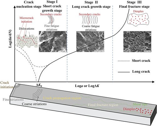
The high cycle fatigue fracture behavior of metals can generally be divided into the following stages [Citation179]: crack nucleation stage, short crack growth stage (state I), long crack growth stage (state II), and final fracture stage (state III), as shown in Figure . At the crack nucleation stage, dislocation accumulation of titanium alloy under HCF load will cause local high stress state which induces twinning, slip or microcracks. The interaction between dislocations will form dislocation cells or dislocation walls, and further result in slip bands [Citation172,Citation180]. Microcracks will grow along or across the grain boundary, then develop into short crack propagation [Citation181,Citation182]. The short crack growth stage can be further divided into microscopic short crack stage and physical short crack stage according to the crack length. During the short crack growth stage, fine fatigue striations can be observed on the crack propagation path, indicating lower FCGR at the initial stage of crack growth. During the long crack growth stage, the distances between fatigue striations will become larger, demonstrating the gradual increase of FCGR with crack growth. Fatigue fractures in this stage always show river patterns, ridge patterns, or tearing ridges, which indicate plastic deformation during crack propagation. LEFM methods are usually used to study the FCG behavior during the long crack growth stage. Finally, the test sample breaks instantaneously under a fatigue load. A large number of dimples can be observed as ductile fracture characteristics, with shear lips appearing on the edge of the fracture. Cracks tend to nucleate from defects (if there are any), and then propagate around. The propagation direction of cracks changes due to the forms of fatigue loads applied to the test sample.
Figure 7. HCF fracture behavior of titanium alloy.
In terms of traditional mechanical evaluation models, scholars have developed many fatigue-prediction models (as shown in Figure ) based on the theory of fracture mechanics, the generalization of Paris’ law, the AM defect analysis of EVS with different PD functions, and the El Haddad and Topper correction of K-T diagram, which give great guidance on fatigue performance evaluation of parts with AM defects.
Figure 8. Development of mechanical models for fatigue properties evaluation of AM processed titanium alloy [Citation95,Citation117,Citation149,Citation183,Citation184].
![Figure 8. Development of mechanical models for fatigue properties evaluation of AM processed titanium alloy [Citation95,Citation117,Citation149,Citation183,Citation184].](/cms/asset/bbb31c94-10b6-4dba-b78b-e2e4babc4924/tmrl_a_2275599_f0008_oc.jpg)
Paris et al. [Citation185] believe that the SIF at the crack tip is the driving force for fatigue crack growth during crack growth stages, so they proposed a formula to describe the law between FCGR and SIF variation range, which is called Paris’ law, and the formula is described as follows.
(1)
(1) where a is the crack length, N is the number of stress cycles, C and m are Paris constants, and ΔK = Kmax − Kmin is the SIF variation range. In LEFM, ΔKth is introduced as the threshold value of crack propagation for the case of infinite life of materials, and KIc is introduced as the fracture toughness for the static failure of materials.
The above Paris equation establishes the relationship between fracture mechanics and fatigue fracture, and firstly gives the method to estimate the fatigue life of structural parts from the perspective of crack propagation. Many research works have been carried out on the application of this equation in different stages and different fields. Both Foreman et al. [Citation186] and Laird [Citation187] studied the modification of the Paris equation in terms of fatigue limit and crack growth threshold. Elber [Citation188] studied the modification of the Paris equation in terms of crack closure. The application of the Paris equation in the short crack growth stage is quite extensive. Pearson [Citation189] studied the use of the Paris equation to predict the growth of cracks from 0.00025 to 0.02 in. El Haddad et al. [Citation190,Citation191] predicted crack length at different cyclic numbers based on the Paris equation and strain intensity factor. Kitagawa and Takahashi [Citation192] discussed the application of fracture mechanics to small cracks in the initial stage. Ritchie and Lankford [Citation193,Citation194] extended the Paris equation to the life prediction analysis of small fatigue crack problems, supporting alloy design. Pugno et al. [Citation183] proposed to combine the S–N curve with the Paris equation when studying the specimen with an initial crack size of ai, and established the generalized Paris Law [Citation195].
The S–N curve (Wöhler curve) describes the fatigue crack behavior of the specimen in the LCF state and HCF state as follows:
(2)
(2) where k is the Wöhler parameter, ΔσR is the stress range when the specimen encounters a static failure, Δσ0 is the fatigue limit of the specimen, Δσ is the stress range at specimen life of Nf, N0, N∞ and Nf are the corresponding cycle number of ΔσR, Δσ0 and Δσ, respectively. For titanium alloy, the values are normally given as N0 = 103, N∞ = 3 × 10⁷ (or 107).
The equation for the specimen with an initial crack size of ai can be established as:
(3)
(3)
Under this condition, the Wöhler parameter in the S–N curve is different from the material constant k in the conventional S–N curve but equivalent to the Paris index m. Therefore, the S–N curve depends on the initial crack size ai, and the fatigue limit obtained from the above formula also depends on ai, being inconsistent with the value directly calculated from the crack growth threshold.
For a given material crack growth threshold ΔKth and fatigue limit Δσ0, the threshold size of the sample under infinite life conditions (called the El Haddad parameter [Citation190]) could be calculated as:
(4)
(4)
Similarly, the threshold size at static failure status could be calculated through the fracture toughness KIc and the tensile strength σR:
(5)
(5)
The Paris equation is extended [Citation183,Citation196], and the relationship between SIF and remote stress σ as well as the relationship between crack length a and fracture quantum Δa is established.
(6)
(6) where Δa is a material parameter related to Δσ. It is correlated with a0 for infinite life cases and a0S for static failure cases. To consider the influence of this additional crack size, Pugno established the generalized Paris Law as follows:
(7)
(7)
The generalized Paris Law realizes the formal matching of the Basquin equation and Paris equation, and fully considers the influence of initial crack size on the FCG behavior of samples. For AM processed titanium alloy, defects introduced in the manufacturing process can be regarded as initial cracks, which must be considered for the AM process. Therefore, it is scientific to evaluate the fatigue performance of AM processed titanium alloy parts based on the generalized Paris Law. In this method, it is a prerequisite to accurately evaluate the defects and use the evaluation results for fatigue prediction.
Usually, the maximum predicted defect size is used for approximate evaluation to avoid characterizing all defects and achieve the equivalence of AM defects and initial cracks. Various PD functions have been used to predict the defect distribution and maximum defect size, including Gumbel distribution based on EVS [Citation197], generalized Pareto distribution [Citation152], Weibull distribution [Citation106], and so on. These methods and models have become essential tools to link the theory of fracture mechanics with the fatigue evaluation model for AM processed parts.
Murakami et al. [Citation198] are the first to propose an EVS method for the prediction of the fatigue limit of metals containing impurities. They defined the square root of the projected area of inclusions in pure steel () as the inclusion size at the crack initiation position and carried out fatigue tests to verify the correlation between the square root and the fatigue limit of pure steel. They used the EVS data of defects observed/sampled from pure steel to predict the maximum defect size in samples and believed that this size determined the fatigue performance of samples. Subsequently, they used the Gumbel Distribution based on EVS to evaluate the inclusion size of the ultra-clean bearing steel manufactured by electron beam remelting and found that the inclusion size was significantly reduced compared with the conventionally manufactured ultra-clean bearing steel [Citation197].
The parametric model can be effectively applied to the fatigue limit assessment of ultra-clean bearing steel with inclusions or minor defects as the fracture initiation point. Murakami et al. [Citation197] analyzed the influences of Vickers hardness, surface defect geometry, and size on fatigue limit based on the fatigue limit test results of more than 15 kinds of materials under rotating bending and tension compression, and established the prediction model among defect size, matrix Vickers hardness and fatigue limit of ultra-clean bearing steel.
(9)
(9) where C is the material parameter related to defect location, C = 1.43 when the defect exists on the surface, C = 1.41 when the defect exists inside but contacts the surface, and C = 1.56 when the defect exists inside the material. σw is the fatigue limit prediction value of the sample, which is an area parameter of the defect. HV is the Vickers hardness, R is the stress ratio, and α = 0.226 + HV × 10−4 is an empirical parameter.
The above formula expresses Murakami et al.’s cognition about defects in structures. As long as the fatigue limit problem is involved, defects occupying three-dimensional space can be treated as cracks. On this basis, Murakami et al. [Citation148] listed both test and analysis results of equivalent area parameters corresponding to different defect shapes, Vickers hardness of defect area, fatigue limit test values, and fatigue limit prediction values, which validated the effectiveness of their prediction model. Subsequently, the research work of Shojima et al. [Citation199] and Matsunaga et al. [Citation200] confirmed that this parameter method applied to Ti-6Al-4V alloy.
After that, researchers applied this method to AM processed parts. Masuo and his collaborators [Citation117] also used the EVS-based parameter method to define the maximum expected defect size in AM processed parts of EBM and DMLS Ti-6Al-4V specimens. They classified the defects in AM processed titanium alloy into five categories:
Internal defects with irregular shapes;
Surface defects with irregular shapes;
Inclined defects in contact with the surface;
Irregular shaped internal defects interacting with the surface;
Two adjacent defects interacting with each other.
The estimation method which could effectively predict defect area has been given for these five types of defects, as shown in Figure . When multiple defects are close to each other, the fatigue crack caused by one defect may be connected with another nearby defect(s). When the distance between defects is less than the maximum size of smaller defects (see Figure (v)), it must be considered to calculate the effective defect area. For the case where multiple small internal defects are close to each other, the minimum circumscribed ellipse should be used to define the effective defect area .
Figure 9. Estimation method of effective area of irregular defects and surface defects. Reprinted with permission from Masuo et al. [Citation117] (Copyright (2018) Elsevier).
![Figure 9. Estimation method of effective area of irregular defects and surface defects. Reprinted with permission from Masuo et al. [Citation117] (Copyright (2018) Elsevier).](/cms/asset/2b7cbf1b-4f5b-42ce-b95b-c4642be268ff/tmrl_a_2275599_f0009_oc.jpg)
On this basis, Masuo et al. [Citation117] introduced the effective defect area into the prediction model (Equation (9)) proposed by Murakami et al. [Citation198] and obtained Equation (10). They used the smooth contour area of constrained irregular shape defects as the effective defect area, and calculated the maximum SIF at the internal or surface cracks along the irregular shape defects by this parameter. They believe that SIF at irregular shape defects drives the cracks into regular circular cracks in the process of crack growth. The work of Wu et al. [Citation201] confirms this assertion, as shown in Figure .
(10)
(10)
Figure 10. Interaction of AM defects under fatigue loading. Reprinted with permission from Wu et al. [Citation201] (Copyright (2017) Elsevier).
![Figure 10. Interaction of AM defects under fatigue loading. Reprinted with permission from Wu et al. [Citation201] (Copyright (2017) Elsevier).](/cms/asset/48633c27-4023-4102-b79a-908cc82c2574/tmrl_a_2275599_f0010_oc.jpg)
The EVS method is also used to evaluate AM defects and quantify defect size through parameters. Günther et al. [Citation106] used the Weibull distribution function to evaluate the fatigue life of SLM and EBM Ti-6Al-4V materials under ultra-high cycle load. They used Weibull probability plots to evaluate the internal crack initiation size in AM processed specimens for defects including LOF, porosity, and α phase cluster. It was found that the porosity and α phase cluster show similar average defect size, while the LOF defect has an obviously larger average size. The effect of defect size on fatigue life was evaluated for specimens that failed due to the three types of internal defects. Sandell et al. [Citation202] used a combined method of X-ray CT test, EVS, and fracture mechanics to predict the fatigue life of the EBM Ti-6Al-4V specimen. The results show that the predicted fatigue life obtained by deterministic FCG calculation with the worst defect observed by X-ray CT test is conservative and accurate, the error lies within the double dispersion band, and no specimen (including those with initial LOF defects) fractured outside the prediction boundary. The only problem is that this model uses very little defect information. After summarizing such methods, Molaei and his collaborators [Citation94,Citation140,Citation142,Citation203] also used EVS to predict the defect distribution in the LPBF Ti-6Al-4V sample. They defined the effective defect size and calculated the most dangerous defect by parameter method; Fatigue was predicted with high accuracy considering various loading statuses such as uniaxial, multiaxial, torsional, etc.
These works show that a series of evaluation models can be used to predict the fatigue performance of AM processed parts regardless of their fatigue life or strength in case the manufacturing defects could be accurately identified and the distribution of the most dangerous defects be predicted. Based on fracture mechanics theory and defect equivalence method, different fatigue evaluation methods have been developed for AM components, such as the local method based on SIF, El Haddad and Topper correction method of K–T diagram, critical distance theory, etc.
Aiming at the fatigue evaluation of welded joints, Atzori et al. [Citation204] collected the stress and strain near the weld toe employing numerical simulation and strain test, predicted the fatigue behavior of welded joints by local method, semi-local method, and structural method based on notched SIF, and compared the advantages and disadvantages of each method. The parameters that affect the fatigue strength prediction are mainly three types: the size of welded joints, the geometry of welded joints, and the application range of nominal stress. The results show that the fatigue design dispersion band based on NSIF local method is applicable to predict the fatigue strength of structural steel weld toes within 6–100 mm thickness. But for AM processed structural parts, it is validated in various studies that AM defects are the most significant factors affecting fatigue performance, and the local stress concentration caused by AM defects affects the hot spot stress of the part, so the evaluation of fatigue strength of AM part by (semi) local method cannot achieve the desired effect.
The K–T diagram is a double logarithmic curve describing the crack length and fatigue failure stress. Kitagawa and Takahashi [Citation192] believe that the crack growth rate is slow at the short crack growth stage. He defines the failure stress at this stage as the fatigue limit of crack-free materials, as shown in Equation (11). At the long crack growth stage, the failure stress decreases significantly with the growth of the crack length, so the failure stress can be described as a function of the crack length (Equation (12)).
(11)
(11)
(12)
(12) where Δσfat is the fatigue limit of crack-free materials, ΔKth is the threshold value of crack growth, a is the crack length, and Y is the geometric correction coefficient (related to crack location).
The two equations for short and long crack stages appear to be two straight lines in the K–T diagram as shown in Figure (a). It is inappropriate to describe the short crack growth stage by a constant model, although its FCGR is low and its failure stress changes little with the crack length before entering the long crack growth stage. Therefore, El Haddad and Topper modified the K–T diagram to solve this problem and obtained a more conservative equation (Equation (14)) using the threshold size a0,fat (Equation (13)) of crack-free material as the material constant.
(13)
(13)
(14)
(14)
Figure 11. K–T diagram with El Haddad and Topper corrections (a) Schematic diagram; (b) Experimental data and simulation results. Reprinted with permission from Wycisk et al. [Citation95]. (Copyright (2014) Elsevier).
![Figure 11. K–T diagram with El Haddad and Topper corrections (a) Schematic diagram; (b) Experimental data and simulation results. Reprinted with permission from Wycisk et al. [Citation95]. (Copyright (2014) Elsevier).](/cms/asset/ecdc2c46-bc75-435b-b0e7-f0937f363934/tmrl_a_2275599_f0011_oc.jpg)
It could be obtained as the following from these two formulae:
(15)
(15)
This correction correlates the failure stress with the initial crack length during the whole crack growth stage, as shown in Figure (a), and leads to a more accurate fatigue limit prediction for cracked specimens in the short crack growth stage. But the prediction result in the long crack growth stage is relatively conservative. The test and simulation results in Wycisk et al.’s work [Citation95] confirm this. They tested the fatigue limit and crack growth behavior of LAM Ti-6Al-4V alloy specimens with surface cracks and volume defects, and simulated and predicted the fatigue limit of the specimens based on the LEFM method. The test and simulation results can be seen in Figure (b). All the fatigue prediction results are conservative for samples with long defects (cracks) in the CT test.
For specimens with AM defects, the accuracy of fatigue prediction by the above models depends largely on the selection of geometric correction factors. In this regard, researchers have given a perfect solution, that is, using Equation (16) to take the geometric correction factor for internal defects [Citation149], and using Equation (17) to take the geometric correction factor for surface defects under HCF condition [Citation184]:
(16)
(16)
(17)
(17) where θ is the angle between the crack front and the sample surface.
Most observations on the fatigue failure initiation position show that fatigue failure often originates from surface failure [Citation205–207]. This can be attributed to the fact that the post-treatment eliminates defects such as pores inside the part, which is also affected by the large stress concentration effect at surface defects. Therefore, surface defects have a greater effect on fatigue failure than internal defects, which is also validated by Murakami [Citation149]. Through fatigue tests on specimens containing inclusions under uniaxial load, it is found that the maximum SIF of an internal defect was about , while that of the surface defect could reach
. This means surface defects are more harmful to fatigue performance than internal defects in case the two defects have similar sizes and shapes. The work of Sanaei and Fatemi [Citation208] also confirms that when dealing with the shear failure mode, defect equivalence can be achieved by projecting the defect area on the maximum shear plane. Therefore, the characterization of the maximum effective defect area of AM processed parts should first focus on surface defects and initial defect size equivalent to surface roughness.
Romano et al. [Citation209] proposed a fatigue crack growth model based on the maximum defect size, which can predict fatigue life and data dispersion within elastic regions. The model is used to predict the uniaxial high cycle fatigue life and fatigue strength of SLM AlSi10Mg specimens and gives highly accurate predicting results. Based on the evaluation of SIF, the most dangerous defect in the CT test sample can be defined, then the maximum defect in the measured volume of the sample can be predicted and calculated by parameters. For a given percentage threshold, the lower limit S-N curve is obtained to evaluate material safety through the manually calculated defined maximum defect size. For the fatigue strength of AM processed part under the short crack growth model considering defects, the influence of defects is introduced into the K-T diagram, and then the K-T diagram is modified to predict fatigue strength. The fatigue life is also estimated by the model based on defect distribution law, and the dispersion band of prediction results is given.
On this basis, with the improvement of computing power, some complex crack growth equations can be solved by numerical methods. For example, the NASGRO equation [Citation210], which accounts for the stress ratio R, crack closure, and tails at the upper and lower ends of the growth rate curve and is described as follows:
(18)
(18) where D and n are material parameters, p and q are empirical coefficients that determine the curvature of the growth rate curve in the tail regions selected to fit the experimental data, and f is the Newman crack closure function [Citation210].
Romano et al. [Citation211] simulated the fatigue crack growth of SLM AlSi10Mg alloy by NASGRO 4.0 software and estimated the fatigue strength and fatigue life based on numerical simulation results. They calculated SIF by the standard solution of surface crack propagation of cylindrical specimens, described the crack size by crack depth a, and approximated the defect shape by a semi-circular crack. The initial crack depth ai was determined by the defect area parameter, the ΔK-da/dN relationship was described by an equation built in NASGRO solver, and the parameters were obtained from the FCG test on CT samples. They calculated three different conditions by the Newman model, and the results showed that the parameter model with plastic correction had the highest prediction accuracy, highlighting the importance of elastic-plastic conditions for correctly analyzing the fatigue performance of structural parts with AM defects.
In addition to NASGRO, there are also commercial crack growth numerical software such as AFGROW and FASTRAN, which use control equations that consider different crack growth and closure mechanisms. Wycisk et al. [Citation95] used AFGROW to predict the HCF fatigue of the LAM Ti-6Al-4V cylindrical specimen, with a stress ratio of 0.1. The finite element software simulation accurately predicted the fatigue life of AM samples with large initial defects, but overestimated the fatigue life of samples with small initial defects, making the later prediction result more dangerous. Fortunately, the El Haddad and Topper corrections gave a conservative assessment of the fatigue limit of smaller initial defects as mentioned above. The combination of these two methods can effectively predict the fatigue limit of AM processed Ti-6Al-4V alloy considering the effect of defects. In recent research, Molaei et al. [Citation212,Citation213] conducted fatigue assessments of notched components using FASTRAN software. Test specimens were assumed to follow the mode I crack initiation and growth with equivalent axial stress to be evaluated starting from the local equivalent von Mises stress using the appropriate stress. It is worth mentioning that, good agreement was found between the prediction and experimental sequences of LAM Ti-6Al-4V specimens in both the AB and machined conditions.
Other theoretical systems such as the critical plane method [Citation214], Von Mises and maximum principal stress criteria [Citation203,Citation215] are the explorative use of traditional methods in this field. However, these methods also have some disadvantages such as insufficient applicability to AM components with different process parameters and failure to consider multiaxial stress states. The application of these methods in the fatigue evaluation of AM processed parts still needs to be further verified.
In summary, further research can be conducted in several specific areas. Firstly, data-driven methods can help link the AM process parameters to fatigue performance, clarifying the role of factors such as grain structure, texture, second phases, residual stresses, etc. in fatigue prediction and guiding the optimization of AM repair processes with numerical simulation methods. Secondly, real-time detection data on defect formation during the AM process [Citation216–218] can serve as an important input parameter for fatigue evaluation, which contributes to a deeper understanding of the fatigue failure mechanism of AM components. Finally, the difficulty in evaluating fatigue of AM components lies in the complex microstructures, defects, and residual stresses. Therefore, developing high-precision in-situ characterization methods [Citation219,Citation220] is an important research direction for the future.
4.2. ML strategy for fatigue evaluation
Many complex factors affect the fatigue properties of AM materials, such as microstructure, residual stress, surface roughness, defects, post-processing, etc. Traditional mechanical models need to combine these factors to improve prediction accuracy, resulting in low efficiency and high cost. Through learning a large amount of testing and simulation data, the ML method can incorporate various AM processes, post-processing, and characterization parameters into the model for fatigue life prediction, fatigue crack behavior, fatigue damage diagnosis, and fatigue strength prediction, as shown in Figure . ML strategy possesses advantages in terms of computation efficiency and prediction accuracy [Citation221]. Nonetheless, the application of ML in predicting fatigue properties of AM materials is still limited, let alone in AM repaired titanium alloy blades.
Figure 12. Summary of the application of applying ML strategy in predicting the fatigue properties of AM materials (Artificial neural network as an example) [Citation222].
![Figure 12. Summary of the application of applying ML strategy in predicting the fatigue properties of AM materials (Artificial neural network as an example) [Citation222].](/cms/asset/cebc5ae1-a130-4e8b-b16f-68c4634a07d8/tmrl_a_2275599_f0012_oc.jpg)
Zhan et al. [Citation223] used the continuum damage mechanics (CDM) and two typical ML models (ANN and RF) to predict the fatigue life of AM Ti-6Al-4V and other aerospace alloys. The input parameters of the ML model include 4 AM processing parameters (laser power P, scanning speed v, hatch space h, powder layer thickness t) and 2 fatigue loads parameters (maximum stress σmax, stress ratio R), and the output is the fatigue life Nf of AM specimens. The CDM-based computational approach is employed to acquire fatigue data to train ML models. The ML computational flowchart is shown in Figure (a). The prediction results show that five fatigue lives predicted by the ANN model locate outside the three-error bands, while all data by the RF model locate within the error band, as shown in Figure (b). This indicates that the ML method can effectively predict the fatigue life of AM alloy.
Figure 13. The fatigue life prediction of AM Ti-6Al-4V alloys with the CDM-ANN/RF method. (a) Computational flowchart; (b) Variation of the predicted fatigue life against experimental data by ML. Reprinted with permission from Zhan et al. [Citation223] (Copyright (2021) Elsevier).
![Figure 13. The fatigue life prediction of AM Ti-6Al-4V alloys with the CDM-ANN/RF method. (a) Computational flowchart; (b) Variation of the predicted fatigue life against experimental data by ML. Reprinted with permission from Zhan et al. [Citation223] (Copyright (2021) Elsevier).](/cms/asset/5cca210f-f790-463a-95ef-72eb2cc0e332/tmrl_a_2275599_f0013_oc.jpg)
In addition, Zhan and his collaborators [Citation224] also used the CDM-RF model to carry out the data-driven prediction of the fatigue life of LMD TA2-TA15 and TC4-TC11 titanium alloys. The input variables of the model are material types and load conditions (σmax, Kt and R), and the output variable is fatigue life Nf. The model strategy is to use the fatigue life under different fatigue loads computed by numerical simulations based on the CDM method and fatigue experiments for training. The trained RF model can be used to predict the fatigue life of AM titanium alloy. Figure (a) is the CDM-RF model strategy. The prediction results show that the fatigue life prediction performance of the CDM-RF method is better than that of the CDM method for AM titanium alloys, as shown in Figure (d,e). For the AM TA2-TA15, the predicted results by the CDM-RF have higher accuracy, especially for the notched specimen (Figure (c)). Finally, it is necessary to take the influence of internal defects into account in the ML model.
Figure 14. The fatigue life prediction of LMD TA2-TA15 and TC4-TC11 titanium alloys with the CDM-RF method. (a) CDM-RF strategy; (b) Smooth specimen; (c) Notched specimen; (d) Prediction results for AM TA2-TA15; (e) Prediction results for AM TC4-TC11. Reprinted with permission from Zhan et al. [Citation224] (Copyright (2021) Elsevier).
![Figure 14. The fatigue life prediction of LMD TA2-TA15 and TC4-TC11 titanium alloys with the CDM-RF method. (a) CDM-RF strategy; (b) Smooth specimen; (c) Notched specimen; (d) Prediction results for AM TA2-TA15; (e) Prediction results for AM TC4-TC11. Reprinted with permission from Zhan et al. [Citation224] (Copyright (2021) Elsevier).](/cms/asset/187eea81-d531-4d90-b70a-befdb0664796/tmrl_a_2275599_f0014_oc.jpg)
Snow et al. [Citation225] trained a CNN model to research the correlation between the process monitoring data (including layerwise imagery, multi-spectral emissions, and laser scanning vector data), part manufacturing defects, and fatigue performance of LPBF Ti-6Al-4V. Defect data was collected through X-ray CT scanning and automated defect recognition software. The CNN classifiers were trained with defect data as input. The model architecture is shown in Figure (a). The training results show that fatigue critical LOF defects can be detected via ML of in situ sensor data. Figure (b) shows the application of the trained CNN to the case of 200 layers, and the defects and fatigue life of the four selected fatigue parts gauge regions have been accurately predicted. The larger the defect density, the lower the fatigue life.
Figure 15. The internal defects and fatigue life prediction of LPBF Ti-6Al-4V alloys with the CNN method. (a) Architecture for defect classification; (b) Fatigue life and XCT results for four fatigue parts from the training and testing data sets. Reprinted with permission from Snow et al. [Citation225] (Copyright (2021) Elsevier).
![Figure 15. The internal defects and fatigue life prediction of LPBF Ti-6Al-4V alloys with the CNN method. (a) Architecture for defect classification; (b) Fatigue life and XCT results for four fatigue parts from the training and testing data sets. Reprinted with permission from Snow et al. [Citation225] (Copyright (2021) Elsevier).](/cms/asset/e9c2e837-4c28-410e-b59a-d6fd7e9ce811/tmrl_a_2275599_f0015_oc.jpg)
Chen et al. [Citation226] proposed a probabilistic physics-guided neural network (PPgNN) method for modeling. AM processing parameters (scanning speed v, laser power P, hatch space H, layer thickness t, heat temperature HT, heat time Ht) can be trained to learn both mean and variance of the fatigue life of SLM Ti-6Al-4V in AB and annealed conditions with this developed model. The architecture used for all data is shown in Figure (a) with the selective neurons for missing data. Figure (b) shows the contrast in predictive performance between models trained with all data (with missing data) and models trained with complete data (without missing data) by the logarithmic scoring rule. The results showed that the model is more likely to produce good predictions by considering the incomplete data set for training. They also compared the sensitivity of process parameters, as shown in Figure (c), and studied the influence of process parameters on the mean and variance of the fatigue life. It is interesting to find that the fatigue life is highly sensitive to post-process parameters (heat temperature HT and heat time Ht) compared to in-process parameters (speed v, power P, hatch space H, and layer thickness t).
Figure 16. The fatigue life prediction of SLM Ti-6Al-4V alloys with the PPgNN method. (a) Architecture for fatigue analysis considering missing data; (b) Prediction comparison between model trained with missing data and model trained with complete data; (c) Sensitivity indicators for process parameters. Reprinted with permission from Chen et al. [Citation226] (Copyright (2021) Elsevier).
![Figure 16. The fatigue life prediction of SLM Ti-6Al-4V alloys with the PPgNN method. (a) Architecture for fatigue analysis considering missing data; (b) Prediction comparison between model trained with missing data and model trained with complete data; (c) Sensitivity indicators for process parameters. Reprinted with permission from Chen et al. [Citation226] (Copyright (2021) Elsevier).](/cms/asset/9b0db229-5ab0-49b9-98ec-395113edab11/tmrl_a_2275599_f0016_oc.jpg)
For predicting the fatigue life of LDED Ti6.5Al2ZrMoV titanium considering the influence of AM microstructures and defects, Dang et al. [Citation227] utilized a support vector regression (SVR) algorithm by post-mortem fractography analysis. The pores can be divided into four types according to the crack initiation modes, namely small pores (d1 < small-size α phase, < 20 µm), medium pores (small-size α phase < d2 < micro-columnar grain, 20–60 µm), big pores (micro-columnar grain < d3, with easily observed facets, > 60 µm) and large pores (micro-columnar grain < d3, with less identifiable facets, >120 µm). ΔK, Pore types, σmax, rd (ratio of distance to the free surface and equivalent diameter of pore), and area (projected area along load direction of pore) were introduced as input variables for different SVR models to compare and analyze the fatigue life prediction results. Results showed that the stress intensity factor range obtained by Murakami’s approach and the pore types determined by the relationship between pore size, microstructure size, and facet were verified to be reasonable input variables for the SVR fatigue life prediction model. The SVR algorithm is an effective approach to obtain the relationship between pore parameters and the fatigue life of the LDED Ti-6.5Al-2Zr-Mo-V titanium alloy.
In summary, it is meaningful to collect a large number of numerical and experimental data to train ML models to predict the fatigue performance of AM components. Nonetheless, the application of ML in predicting the fatigue properties of AM alloys is still rare, especially for the fatigue limit prediction of aero-engine titanium alloy blades. This is due to the lack of fatigue limit experimental data in the published literature and the high time-consuming and high cost of the test process. If the challenges such as data volume, defect identification, blade structure, and load characteristics can be solved, ML is expected to become a powerful tool for the efficient and accurate prediction of fatigue properties of AM repaired aero-engine blades.
4.3. Fatigue evaluation considering the operational environment of compressor blades
The complex operational environment of compressor blades poses a huge challenge to the prediction of fatigue properties. Byrne et al. [Citation228] identified two states of crack propagation in compressors. The first type is the LCF mode dominated by centrifugal force, where the influence of HCF related cycles on crack propagation is minimal, and the crack propagation speed can be ignored. The second is that LCF driven cracks propagate to a certain extent, causing the SIF under resonance conditions to be greater than the threshold, and HCF driven cracks continue to propagate.
The complex operational environment of the compressor makes it impossible to monitor the crack initiation and propagation of the blade during service. Numerical simulation is an important means of fatigue prediction and evaluation [Citation229] but with low accuracy. Zhu et al. [Citation230] adopted the Chaboche plastic model and the Fatemi-society criterion to establish a method for fatigue life prediction and reliability assessment of 950X steel turbine disks, based on the probabilistic framework for multi-axis LCF evaluation of notch components and the combination of finite element simulation with engine load spectrum. Wang et al. [Citation231] studied the crack growth behavior of the FV520B-I blade under centrifugal and aerodynamic loads, as well as the stress distribution and fatigue life at the critical position, and established the fatigue life evaluation model of the blade. However, there are too many simplifications in the process of numerical calculation, resulting in a large difference between the simulation loads and the in-service condition.
In fact, fatigue evaluation of AM compressor blades considering in-service loads is very rare. Qu et al. [Citation232] predicted the fatigue crack growth life of the SLM Ti-6Al-4V compressor impeller considering the comprehensive influence of AM residual stress and external load. However, they only studied the fatigue crack growth life at the start-up and stop stages, which is a relatively harsh load condition. Although the randomness of the simulation under such conditions is very small, it only covers a small part of the aero-engine operating conditions.
At present, deterministic life prediction methods for complex operating conditions [Citation233] and specific load spectra [Citation234] have been developed, which have been applied to predict the fatigue failure of compressor impellers. The microstructure, residual stress, and manufacturing defects of AM process make it difficult to predict the fatigue crack initiation and propagation of AM repaired compressor blades. Therefore, the fatigue evaluation method of AM aero-engine blades considering in-service operating conditions and AM characteristics still needs to carry out a lot of research and verification work to ensure the safety of use.
5. Summary and outlooks
In summary, we have introduced the application of AM in the repair of aero-engine blades and presented a comprehensive overview on the latest progress of the influencing factors on fatigue behavior of AM parts and predicting fatigue properties of AM repaired blades by various methods.
The repair technology used for aero-engine blades has gradually changed from grinding repair to AM repair. Grinding can deal with small-scale damage, and reduce the stress concentration in damaged areas, but the grinding gap remains as the source of fatigue cracks. In addition, grinding cannot restore blade shape, which certainly affects the aerodynamic performance of the compressor. AM repair can cover the shortage of grinding and restore the blade shape, but it introduces a residual stress field during hot processing and causes differences in the structure of the repaired area and the matrix, affecting the mechanical properties and fatigue performance of the blade. Many cases of AM repaired blades showed that AM process still has to go a long way before it could replace grinding in repairing aero-engine blades, and there are some key problems to be solved including the control of material structure, AM defects, and residual stress.
The inherent properties of AM process such as microstructure, manufacturing defects, surface roughness, residual stress as well as their complex interactions make the fatigue crack initiation and propagation behavior of AM processed parts very complicated. Among them, LOF and porosity defects have the greatest impact on the fatigue performance of AM parts, while the effect of residual stress is not significant. Some post-treatments could effectively weaken the influence of AM defects. For example, HIP can close pores, M&P can improve surface roughness, and annealing can eliminate residual stress and regulate microstructure. But it should be noted that some post-treatments are not applicable engineeringly. The evolution characteristics and interactions of inherent properties of AM processed blades still show significant impacts on the fatigue performance under service conditions although considerable efforts have been made in the research of FCG behavior and fatigue properties of AM processed parts in recent years. This should be the focus to be studied to promote the application of AM repair in engineering. Conversely, the study can also provide help for the damage tolerance design of AM processed blades.
The evaluation of fatigue strength of AM processed blades started from fracture mechanics and focused on the size, shape, and location of AM defects. The breakthrough in the characterization and evaluation technology of AM defects supported the development of fatigue evaluation. However, current fatigue prediction models (regardless of prediction for fatigue limit or fatigue life) are limited to fitting or dimensional image correlation with fatigue test results, generally based on phenomena and laws among physical parameters, lacking in-depth research on the physical mechanism of fatigue damage of AM parts. It can be foreseen that further study on AM defects evolution and interaction under in-service loads will improve the accuracy of fatigue evaluation for AM processed blades. With the development of computing technology, big data, and machine learning methods will have more applications in the field of fatigue evaluation for AM processed blades, and gradually become important means to ensure the structural strength and reliability of AM parts.
Acknowledgements
The authors thank the anonymous reviewers for their critical and constructive review of the manuscript.
Disclosure statement
No potential conflict of interest was reported by the author(s).
Data availability statement
The datasets generated during and/or analyzed during the current study are available from the corresponding author on reasonable request.
Additional information
Funding
References
- Liu DX, Chen G. Aeroengine: the heart of aircraft. Beijing: Aviation Industry Press; 2003. (in Chinese)
- MIL-HDBK-1783A, US Department of Defense; 1999.
- MIL-HDBK-1783B, US Department of Defense; 2002.
- GJB 241A-2010. General specification for aero turbojet and turbofan engines. Beijing: Equipment Development Department of the Central Military Commission; 2010. (in Chinese)
- Garrison B. High cycle fatigue (HCF) science and technology program 2000 annual report; 2001.
- Bartsch TM. High cycle fatigue (HCF) science and technology program 2002 annual report. High Cycle Fatig Sci Technol Prog Annual Rep. 2003: 40–43.
- Sikan F, Wanjara P, Atabay SE, et al. Evaluation of electron beam wire-fed deposition technology for titanium compressor blade repair. Mater Today Comm. 2023;35. doi:10.1016/j.mtcomm.2023.105701
- Cowles BA. High cycle fatigue in aircraft gas turbines – an industry perspective. Int J Fract. 1996;80(2):147–163. doi:10.1007/BF00012667
- Zhang T, Chen W, Guan YP, et al. Study on titanium alloy TC4 ballistic penetration resistance part I:ballistic impact tests. Chinese J Aeronaut. 2012;25:388–395. doi:10.1016/S1000-9361(11)60402-0
- Zhang T, Chen W, Guan YP, et al. Study on ballistic penetration resistance of titanium alloy TC4, part II: numerical analysis. Chinese J Aeronaut. 2013;3:606–613. doi:10.1016/j.cja.2013.04.013
- Zhao ZH, Wang LF, Lu K, et al. Effect of foreign object damage on high-cycle fatigue strength of titanium alloy for aero-engine blade. Eng Fail Anal. 2020;118:104842. doi:10.1016/j.engfailanal.2020.104842
- Ma C, Wang YN, Wu YG, et al. Hard object impact damage characteristics of aero engine fan blade. J Aerospace Power. 2017;5:1105–1111. (in Chinese)
- Nie XF, He WF, Li QP, et al. Experiment investigation on microstructure and mechanical properties of TC17 titanium alloy treated by laser shock peening with different laser fluence. J Laser Appl. 2013;25(4):1892–1898.
- Nie XF, He WF, Zhou LC, et al. Experiment investigation of laser shock peening on TC6 titanium alloy to improve high cycle fatigue performance. Mater Sci Eng: A. 2014;594:161–167. doi:10.1016/j.msea.2013.11.073
- Luong H, Hill MR. The effects of laser peening and shot peening on high cycle fatigue in 7050-T7451 aluminum alloy. Mater Sci Eng: A. 2010;527(3):699–707. doi:10.1016/j.msea.2009.08.045
- Maleki E, Unal O, Guagliano M, et al. The effects of shot peening, laser shock peening and ultrasonic nanocrystal surface modification on the fatigue strength of Inconel 718. Mat Sci Eng: A. 2021;810:141029. doi:10.1016/j.msea.2021.141029
- Denkena B, Boess V, Nespor D, et al. Engine blade regeneration: a literature review on common technologies in terms of machining. Int J Adv Manufact Technol. 2015;81(5–8):917–924. doi:10.1007/s00170-015-7256-2
- Zhuo YM, Chen YY, Yang CL. Research status and prospect of welding repair technology for aero-engine blades. Aeronaut Manufact Technol. 2021;64(8):22–28. (in Chinese)
- Brennan MC, Keist JS, Palmer TA. Defects in metal additive manufacturing processes. J Mater Eng Perfor. 2021;30(7):4808–4818. doi:10.1007/s11665-021-05919-6
- Aschenbruck J, Adamczuk R, Seume JR. Recent progress in turbine blade and compressor blisk regeneration. Procedia Cirp. 2014;22(1):256–262. doi:10.1016/j.procir.2014.07.016
- Langen D, Maier HJ, Hassel T. The effect of SiC addition on microstructure and mechanical properties of gas tungsten arc-welded Ti-6Al-4V alloy. J Mater Eng Perfor. 2018;27(1):253–260. doi:10.1007/s11665-017-3091-y
- Tang CL, Wen JQ, Zhang WX, et al. 3D printing technology for titanium alloy and its defect. J Aeronautical Mater. 2019;39(1):38–47. in Chinese.
- Zhao Z, Chen J, Zhang Q, et al. Microstructure and mechanical properties of laser additive repaired Ti17 titanium alloy. Trans Nonferrous Metal Soc China. 2017;27:2613–2621. doi:10.1016/S1003-6326(17)60289-9
- Pan B, Huang YC, Li LQ, et al. Effects of multiple laser repairs on microstructure and hardness of ZTC4 titanium alloy. Chinese J Laser. 2019;46(10):1002011. (in Chinese) doi:10.3788/CJL201946.1002011
- Chastand V, Tezenas A, Cadoret Y, et al. Fatigue characterization of titanium Ti-6Al-4V samples produced by additive manufacturing. Procedia Struct Integ. 2016;2:3168–3176. doi:10.1016/j.prostr.2016.06.395
- Ren XP, Li HQ, Guo H, et al. A comparative study on mechanical properties of Ti-6Al-4V alloy processed by additive manufacturing vs. traditional processing. Mater Sci Eng: A. 2021;817.
- Ackers MA, Messé OMDM, Manninen N, et al. Additive manufacturing of TTFNZ (Ti-4.5Ta-4Fe-7.5Nb-6Zr), a novel metastable β-titanium alloy for advanced engineering applications. J Alloys Compound. 2022;920. doi:10.1016/j.jallcom.2022.165899
- Bian HY, Zuo SG, Qu S, et al. Microstructure and mechanical properties of heat treatment TA15/ TC17 titanium alloy by laser deposition repair. Chinese J Rare Matel. 2020;44(5):455–461. (in Chinese)
- Luo SH, He WF, Chen K, et al. Regain the fatigue strength of laser additive manufactured Ti alloy via laser shock peening. J Alloys Compound. 2018;750:626–635. doi:10.1016/j.jallcom.2018.04.029
- Chi J, Cai Z, Wan Z, et al. Effects of heat treatment combined with laser shock peening on wire and arc additive manufactured Ti17 titanium alloy: microstructures, residual stress and mechanical properties. Surf Coat Technol. 2020;396:125908.
- Chi J, Cai Z, Zhang H, et al. Combining manufacturing of titanium alloy through direct energy deposition and laser shock peening processes. Mater Design. 2021;203:109626.
- Tan C, Weng F, Sui S, et al. Progress and perspectives in laser additive manufacturing of key aeroengine materials. Int J Machine Tool Manufact. 2021;170:103804. doi:10.1016/j.ijmachtools.2021.103804
- Blakey-Milner B, Gradl P, Snedden G, et al. Metal additive manufacturing in aerospace: a review. Mater Design. 2021;209:110008.
- Kanishka K, Acherjee B. A systematic review of additive manufacturing-based remanufacturing techniques for component repair and restoration. J Manufact Process. 2023;89:220–283. doi:10.1016/j.jmapro.2023.01.034
- Liu F, Xie H, He W. Multi-field coupling fatigue behavior of laser additively manufactured metallic materials: a review. J Mater Res Technol. 2023;22:2819–2843. doi:10.1016/j.jmrt.2022.12.112
- Foti P, Razavi N, Fatemi A, et al. Multiaxial fatigue of additively manufactured metallic components: A review of the failure mechanisms and fatigue life prediction methodologies. Prog Mater Sci. 2023;137. doi:10.1016/j.pmatsci.2023.101126
- Sanaei N, Fatemi A. Defects in additive manufactured metals and their effect on fatigue performance: A state-of-the-art review. Prog Mater Sci. 2021: 117.
- Shamsaei N, Yadollahi A, Bian L, et al. An overview of direct laser deposition for additive manufacturing; part II: mechanical behavior, process parameter optimization and control. Addit Manufact. 2015;8:12–35. doi:10.1016/j.addma.2015.07.002
- Thompson SM, Bian L, Shamsaei N, et al. An overview of direct laser deposition for additive manufacturing; part I: transport phenomena, modeling and diagnostics. Addit Manufact. 2015;8:36–62. doi:10.1016/j.addma.2015.07.001
- Fotovvati B, Namdari N, Dehghanghadikolaei A. Fatigue performance of selective laser melted Ti6Al4 V components: state of the art. Mater Res Exp. 2018;6(1). doi:10.1088/2053-1591/aae10e
- Romero C, Yang F, Bolzoni L. Fatigue and fracture properties of Ti alloys from powder-based processes – a review. Int J Fatig. 2018;117:407–419. doi:10.1016/j.ijfatigue.2018.08.029
- Liu S, Shin YC. Additive manufacturing of Ti6Al4 V alloy: A review. Mater Design. 2019;164:107552. doi:10.1016/j.matdes.2018.107552
- Dutta B, Froes FH. The additive manufacturing (AM) of titanium alloys. Titanium Powder Metall. 2015:447–468. doi:10.1016/B978-0-12-800054-0.00024-1
- Agius D, Kourousis K, Wallbrink C. A review of the As-built SLM Ti-6Al-4V mechanical properties towards achieving fatigue resistant designs. Metals. 2018;8(1). doi:10.3390/met8010075
- Yin ZY, Liu TY. Structural strength design of aeroengines. Beijing: Science Press; 2022. (in Chinses)
- Frazier WE. Metal additive manufacturing: a review. J Mater Eng Perfor. 2014;23(6):1917–1928. doi:10.1007/s11665-014-0958-z
- ASTM International. Standard terminology for additive manufacturing technologies. Pennsylvania: ASTM International; 2013.
- Zhao XH, Zuo ZB, Han ZY, et al. A review on powder titanium alloy 3D printing technology. Mater Rep. 2016;30(12):120–126. (in Chinese)
- DebRoy T, Wei HL, Zuback JS, et al. Additive manufacturing of metallic components – process, structure and properties. Prog Mater Sci. 2018;92:112–224. doi:10.1016/j.pmatsci.2017.10.001
- Zhai Y, Galarraga H, Lados DA. Microstructure evolution, tensile properties, and fatigue damage mechanisms in Ti-6Al-4V alloys fabricated by two additive manufacturing techniques. Procedia Eng. 2015;114:658–666. doi:10.1016/j.proeng.2015.08.007
- Simonelli M, Tse YY, Tuck C. Effect of the build orientation on the mechanical properties and fracture modes of SLM Ti–6Al–4 V. Mater Sci Eng: A. 2014;616:1–11. doi:10.1016/j.msea.2014.07.086
- Galati M, Iuliano L. A literature review of powder-based electron beam melting focusing on numerical simulations. Addit Manufact. 2018;19:1–20. doi:10.1016/j.addma.2017.11.001
- Wei HL, Mukherjee T, Zhang W, et al. Mechanistic models for additive manufacturing of metallic components. Prog Mater Sci. 2021;116.
- Sinha A, Swain B, Behera A, et al. A review on the processing of aero-turbine blade using 3D print techniques. J Manufact Mater Process. 2022;6(1). doi:10.3390/jmmp6010016
- Chatterjee B, Bhowmik S. Chapter 9 – evolution of material selection in commercial aviation industry – a review. In: Kumar K, Zindani D, Davim P, editors. Sustainable engineering products and manufacturing technologies. Academic Press; 2019. p. 199–219.
- LEAP-1A-72-21-20-01A-655B-C fan blades (R001) blending (metal leading edge). CFM International; 2019. p. 13.
- Boeing 737-300/400/500 aircraft maintenance manual chapter 72 enging CFM56-3. The Boeing Company; 2005. p. 379.
- Boeing 737-600/700/800/900 aircraft maintenance manual chapter 72 enging CFM56-7. The Boeing Company; 2005. p. 298.
- Zhang ZX, Zeng W, Bian X, et al. Failure analysis of a first stage turbine blade made of directionally solidified GTD111 superalloy and repaired by welding process. Eng Fail Anal. 2023.
- Sayilgan V, Reker D, Bernhard R, et al. Single-crystal repair of high-pressure single-crystal turbine blades for industrial conditions. Procedia CIRP. 2022;111:233–236. doi:10.1016/j.procir.2022.08.056
- Patriarca L, Foletti S, Beretta S, et al. A low-cycle fatigue life prediction model for Alloy625 arc wire welding repairs of gas turbine blades. Theo Appl Fract Mech. 2020;107. doi:10.1016/j.tafmec.2020.102558
- Ou J, Zou L, Wan QH, et al. Weld-seam identification and model reconstruction of remanufacturing blade based on three-dimensional vision. Adv Eng Informat. 2021;49.
- Gao J, Chen X, Yilmaz O, et al. An integrated adaptive repair solution for complex aerospace components through geometry reconstruction. Int J Adv Manufact Technol. 2007;36(11–12):1170–1179.
- Kumar A, Kumar N, Mahto MK, et al. Impression creep behaviour of different zones of pulsed gas tungsten arc welded Ti-6Al-4V alloy. Mater Today Comm. 2023;36. doi:10.1016/j.mtcomm.2023.106722
- Chen JT, Li HZ, Liu YZ, et al. Deformation behavior and microstructure characteristics of the laser-welded Ti-6Al-4V joint under variable amplitude fatigue. Mater Char. 2023;196.
- Wanjara P, Watanabe K, de Formanoir C, et al. Titanium alloy repair with wire-feed electron beam additive manufacturing technology. Adv Mater Sci Eng. 2019;2019:1–23. doi:10.1155/2019/3979471
- Abbott D, Arcella F. Laser forming titanium components. Adv Mater Process. 1998;153:29–30.
- Lewis GK, Schlienger E. Practical considerations and capabilities for laser assisted direct metal deposition. Mater Design. 2000;21(4):417–423. doi:10.1016/S0261-3069(99)00078-3
- Gäumann M, BezenÇon C, Canalis P, et al. Single-crystal laser deposition of superalloys: processing–microstructure maps. Acta Mater. 2001;49(6):1051–1062. doi:10.1016/S1359-6454(00)00367-0
- Keicher DM, Romero JA, Atwood CL, et al. Free form fabrication using the laser engineered net shaping (LENS{trademark}) process. Sandia Nat Lab. 1996: 1–9.
- Keicher DM, Miller WD. LENSTM moves beyond RP to direct fabrication. Metal Powder Rep. 1998;53(12):26–28(3). doi:10.1016/S0026-0657(99)80073-3
- Bi G, Gasser A. Restoration of nickel-base turbine blade knife-edges with controlled laser aided additive manufacturing. Phys Procedia. 2011;12:402–409. doi:10.1016/j.phpro.2011.03.051
- Kaierle S, Overmeyer L, Alfred I, et al. Single-crystal turbine blade tip repair by laser cladding and remelting. CIRP J Manufact Sci Technol. 2017;19:196–199. doi:10.1016/j.cirpj.2017.04.001
- Lepski D, Brückner F. Laser cladding. Berlin: Springer Netherlands; 2009.
- Wang W. Research on ill bonding of Ti-6Al-4V titanium alloy in laser rapid repair processing. Shaanxi: Northwestern Polytechnical University; 2007.
- Huang Y, Chen J, Zhang FY, et al. Influence of heat treatment on microstructure of laser solioforming Ti-6.5A1-3.5Mo-1.5Zr-0.25Si alloys. Rare Metal Mater Eng. 2009;38(12):2146–2150. (in Chinese)
- Wang JW, Chen J, Liu YH, et al. Research on microstructure of TC17 titanium alloy fabricated by laser solid forming. Chinese J Lasers. 2010;37(3):847–851. (in Chinese). doi:10.3788/CJL20103703.0847
- Ming XL, Chen J, Tan H, et al. Research on persistent fracture mechanism of laser forming repaired GH4169 superalloy. Chinese J Lasers. 2015;42(4):63–69. (in Chinese)
- Ming XL, Chen J, Tan H, et al. Coarsening behavior of γ″ precipitates in GH4169 superalloy fabricated by laser solid forming. J Mater Eng. 2014;8:8–14. (in Chinese)
- Lu PH, Liu JR, Xue L, et al. Microstructure and cracking behavior of K418 superalloy by laser forming repairing. Rare Metal Mater Eng. 2012;41(2):315–319. (in Chinese)
- Wang HM. Materials’ funamental lssues of laser additive manufacturing for high performance large metallic components. Acta Aeronautica et Astronautica Sinica. 2014;35(10):2690–2698. (in Chinese)
- Qian TT, Liu D, Tian XJ, et al. Microstructure of TA2/TA15 graded structural material by laser additive manufacturing process. Trans Nonferr Metal Soc China. 2014;24:2729–2736. doi:10.1016/S1003-6326(14)63404-X
- Zhu YY, Chen B, Tang HB, et al. Influence of heat treatments on microstructure and mechanical properties of laser additive manufacturing Ti-5Al-2Sn-2Zr-4Mo-4Cr titanium alloy. Trans Nonferr Metal Soc China. 2018;28(1):36–46. doi:10.1016/S1003-6326(18)64636-9
- Paydas H, Mertens A, Carrus R, et al. Laser cladding as repair technology for Ti–6Al–4 V alloy: influence of building strategy on microstructure and hardness. Mater Design. 2015;85:497–510. doi:10.1016/j.matdes.2015.07.035
- Shrestha S, Panakarajupally RP, Kannan M, et al. Analysis of microstructure and mechanical properties of additive repaired Ti–6Al–4 V by direct energy deposition. Mater Sci Eng: A. 2021;806. doi:10.1016/j.msea.2020.140604
- Shrestha S, El Rassi J, Kannan M, et al. Fracture toughness and fatigue crack growth rate properties of AM repaired Ti–6Al–4 V by direct energy deposition. Mater Sci Eng: A. 2021;823. doi:10.1016/j.msea.2021.141701
- Ojo SA, Shrestha S, Manigandan K, et al. Application of small geometry specimens to determine the fatigue crack growth anisotropy of Ti–6Al–4 V additively manufactured for repair. Res Mater. 2022;15:100309.
- Ojo SA, Shrestha S, El Rassi J, et al. The use of compact specimens to determine fracture toughness anisotropy of Ti–6Al–4 V additively manufactured for repair. Mater Sci Eng: A. 2021;823:141779.
- Ge MZ, Tang Y, Zhang YK, et al. Enhancement in fatigue property of Ti-6Al-4V alloy remanufactured by combined laser cladding and laser shock peening processes. Surf Coat Technol. 2022: 444:128671.
- Wang ZD, Yang K, Chen MZ, et al. Investigation of the microstructure and mechanical properties of Ti–6Al–4 V repaired by the powder-blown underwater directed energy deposition technique. Mater Sci Eng: A. 2022: 831:142186.
- Eylon D, Froes FH. Tensile and fatigue strength improvement of titanium PM alloys through microstructural refinement. In: Kettunen PO, LepistÖ TK, Lehtonen ME, editor. Strength of metals and alloys (ICSMA 8). Oxford: Pergamon; 1989. p. 527–533.
- Eylon D, Vogt RG, Froes FH. Property improvement of low chlorine titanium alloy blended elemental powder compacts by microstructure modification. Progr Powder Metall. 1986;42:625–634.
- Hagiwara M, Kaieda Y, Kawabe Y, et al. Fatigue property enhancement of α-β titanium alloys by blended elemental P/M approach. ISIJ Int. 1991;31:922–930. doi:10.2355/isijinternational.31.922
- Molaei R, Fatemi A, Phan N. Significance of hot isostatic pressing (HIP) on multiaxial deformation and fatigue behaviors of additive manufactured Ti-6Al-4V including build orientation and surface roughness effects. Int J Fatig. 2018;117:352–370. doi:10.1016/j.ijfatigue.2018.07.035
- Wycisk E, Solbach A, Siddique S, et al. Effects of defects in laser additive manufactured Ti-6Al-4V on fatigue properties. Phys Procedia. 2014;56:371–378. doi:10.1016/j.phpro.2014.08.120
- Leuders S, Thöne M, Riemer A, et al. On the mechanical behaviour of titanium alloy TiAl6V4 manufactured by selective laser melting: fatigue resistance and crack growth performance. Int J Fatig. 2013;48:300–307. doi:10.1016/j.ijfatigue.2012.11.011
- Kumar P, Prakash O, Ramamurty U. Micro-and meso-structures and their influence on mechanical properties of selectively laser melted Ti-6Al-4V. Acta Mater. 2018;154:246–260. doi:10.1016/j.actamat.2018.05.044
- Kumar P, Ramamurty U. High cycle fatigue in selective laser melted Ti-6Al-4V. Acta Mater. 2020;194:305–320. doi:10.1016/j.actamat.2020.05.041
- Choi YR, Sun SD, Liu Q, et al. Influence of deposition strategy on the microstructure and fatigue properties of laser metal deposited Ti-6Al-4V powder on Ti-6Al-4V substrate. Int J Fatig. 2020;130:105236. doi:10.1016/j.ijfatigue.2019.105236
- Razavi SMJ, Berto F. Directed energy deposition versus wrought Ti-6Al-4V: a comparison of microstructure, fatigue behavior, and notch sensitivity. Adv Eng Mater. 2019;21(8):1900220. doi:10.1002/adem.201900220
- Kahlin M, Ansell H, Basu D, et al. Improved fatigue strength of additively manufactured Ti6Al4 V by surface post processing. Int J Fatig. 2020;134:105497. doi:10.1016/j.ijfatigue.2020.105497
- Hu YN, Wu SC, Wu ZK, et al. A new approach to correlate the defect population with the fatigue life of selective laser melted Ti-6Al-4V alloy. Int J Fatig. 2020;136:105584. doi:10.1016/j.ijfatigue.2020.105584
- Yan X, Yin S, Chen C, et al. Fatigue strength improvement of selective laser melted Ti6Al4 V using ultrasonic surface mechanical attrition. Mater Res Lett. 2019;7(8):327–333. doi:10.1080/21663831.2019.1609110
- Edwards P, Ramulu M. Fatigue performance evaluation of selective laser melted Ti–6Al–4V. Mater Sci Eng: A. 2014;598:327–337. doi:10.1016/j.msea.2014.01.041
- Pegues J, Roach M, Scott Williamson R, et al. Surface roughness effects on the fatigue strength of additively manufactured Ti-6Al-4V. Int J Fatig. 2018;116:543–552. doi:10.1016/j.ijfatigue.2018.07.013
- Günther J, Krewerth D, Lippmann T, et al. Fatigue life of additively manufactured Ti–6Al–4 V in the very high cycle fatigue regime. Int J Fatig. 2017;94:236–245. doi:10.1016/j.ijfatigue.2016.05.018
- Kasperovich G, Hausmann J. Improvement of fatigue resistance and ductility of TiAl6V4 processed by selective laser melting. J Mater Process Technol. 2015;220:202–214. doi:10.1016/j.jmatprotec.2015.01.025
- Gong H, Rafi K, Gu H, et al. Influence of defects on mechanical properties of Ti–6Al–4 V components produced by selective laser melting and electron beam melting. Mater Design. 2015;86:545–554. doi:10.1016/j.matdes.2015.07.147
- Benedetti M, Fontanari V, Bandini M, et al. Low- and high-cycle fatigue resistance of Ti-6Al-4V ELI additively manufactured via selective laser melting: mean stress and defect sensitivity. Int J Fatig. 2018;107:96–109. doi:10.1016/j.ijfatigue.2017.10.021
- Rafi HK, Karthik NV, Gong H, et al. Microstructures and mechanical properties of Ti6Al4 V parts fabricated by selective laser melting and electron beam melting. J Mater Eng Perfor. 2013;22(12):3872–3883. doi:10.1007/s11665-013-0658-0
- Xu W, Sun S, Elambasseril J, et al. Ti-6Al-4V additively manufactured by selective laser melting with superior mechanical properties. Mineral Metal Mater Soc. 2015;67(3):668–673. doi:10.1007/s11837-015-1297-8
- Greitemeier D, Dalle Donne C, Schoberth A, et al. Uncertainty of additive manufactured Ti-6Al-4V: chemistry, microstructure and mechanical properties. Appl Mech Mater. 2015;807:169–180. doi:10.4028/www.scientific.net/AMM.807.169
- Hrabe N, Gnäupel-Herold T, Quinn T. Fatigue properties of a titanium alloy (Ti–6Al–4 V) fabricated via electron beam melting (EBM): effects of internal defects and residual stress. Int J Fatig. 2017;94:202–210. doi:10.1016/j.ijfatigue.2016.04.022
- Mower TM, Long MJ. Mechanical behavior of additive manufactured, powder-bed laser-fused materials. Mater Sci Eng: A. 2016;651:198–213. doi:10.1016/j.msea.2015.10.068
- Wang X, He X, Wang T, et al. Internal pores in DED Ti-6.5Al-2Zr-Mo-V alloy and their influence on crack initiation and fatigue life in the mid-life regime. Addit Manufact. 2019;28:373–393. doi:10.1016/j.addma.2019.05.007
- Greitemeier D, Palm F, Syassen F, et al. Fatigue performance of additive manufactured TiAl6V4 using electron and laser beam melting. Int J Fatig. 2017;94:211–217. doi:10.1016/j.ijfatigue.2016.05.001
- Masuo H, Tanaka Y, Morokoshi S, et al. Influence of defects, surface roughness and HIP on the fatigue strength of Ti-6Al-4V manufactured by additive manufacturing. Int J Fatig. 2018;117:163–179. doi:10.1016/j.ijfatigue.2018.07.020
- Wycisk E, Emmelmann C, Siddique S, et al. High cycle fatigue (HCF) performance of Ti-6Al-4V alloy processed by selective laser melting. Adv Mater Res. 2013;816–817:134–139. doi:10.4028/www.scientific.net/AMR.816-817.134
- Kahlin M, Ansell H, Moverare JJ. Fatigue behaviour of notched additive manufactured Ti6Al4 V with as-built surfaces. Int J Fatig. 2017;101:51–60. doi:10.1016/j.ijfatigue.2017.04.009
- Bagehorn S, Wehr J, Maier HJ. Application of mechanical surface finishing processes for roughness reduction and fatigue improvement of additively manufactured Ti-6Al-4V parts. Int J Fatig. 2017;102:135–142. doi:10.1016/j.ijfatigue.2017.05.008
- Greitemeier D, Dalle Donne C, Syassen F, et al. Effect of surface roughness on fatigue performance of additive manufactured Ti–6Al–4 V. Mater Sci Technol. 2015;32:1743284715Y.000.
- Becker TH, Kumar P, Ramamurty U. Fracture and fatigue in additively manufactured metals. Acta Mater. 2021;219:117240. doi:10.1016/j.actamat.2021.117240
- Karthik GM, Kim HS. Heterogeneous aspects of additive manufactured metallic parts: a review. Metal Mater Int. 2021;27(1):1–39. doi:10.1007/s12540-020-00931-2
- Liu D, Tang B, Zhu X, et al. Improvement of the fretting fatigue and fretting wear of Ti6Al4 V by duplex surface modification. Surf Coat Technol. 1999;116–119:234–238. doi:10.1016/S0257-8972(99)00279-0
- Joshi V, Lavender C, Moxson V, et al. Development of Ti-6Al-4V and Ti-1Al-8V-5Fe alloys using low-cost TiH 2 powder feedstock. J Mater Eng Perfor. 2013;22(4):995–1003. doi:10.1007/s11665-012-0386-x
- Wirth G, Grundhoff KJ, Smarsly W. Correlations between post-hip treatment, resulting microstructure and fatigue behaviour of prealloyed Ti-6Al-4V powder compacts. Overcom Mater Bound. 1985;17:125–134.
- Cao Y, Zeng F, Liu B, et al. Characterization of fatigue properties of powder metallurgy titanium alloy. Mater Sci Eng: A. 2016;654:418–425. doi:10.1016/j.msea.2015.12.058
- Chen G, Zhao SY, Tan P, et al. A comparative study of Ti-6Al-4V powders for additive manufacturing by gas atomization, plasma rotating electrode process and plasma atomization. Powder Technol. 2018;333:38–46. doi:10.1016/j.powtec.2018.04.013
- Haar T, Becker GM, H T. The influence of microstructural texture and prior beta grain recrystallisation on the deformation behaviour of laser powder bed fusion produced Ti–6Al–4 V. Mater Sci Eng: A. 2021;814:141185. doi:10.1016/j.msea.2021.141185
- De Formanoir C, Martin G, Prima F, et al. Micromechanical behavior and thermal stability of a dual-phase α+α’ titanium alloy produced by additive manufacturing. Acta Mater. 2019;162:149–162. doi:10.1016/j.actamat.2018.09.050
- ASTM. ASTM E3166-20: standard guide for nondestructive examination of metal additively manufactured aerospace parts after build 1. ASTM Int. 2022: 1–63.
- Li P, Warner DH, Fatemi A, et al. Critical assessment of the fatigue performance of additively manufactured Ti–6Al–4 V and perspective for future research. Int J Fatig. 2016;85:130–143. doi:10.1016/j.ijfatigue.2015.12.003
- Sterling AJ, Torries B, Shamsaei N, et al. Fatigue behavior and failure mechanisms of direct laser deposited Ti–6Al–4 V. Mater Sci Eng: A. 2016;655:100–112. doi:10.1016/j.msea.2015.12.026
- Yadollahi A, Shamsaei N, Thompson SM, et al. Effects of building orientation and heat treatment on fatigue behavior of selective laser melted 17-4 PH stainless steel. Int J Fatig. 2017;94:218–235. doi:10.1016/j.ijfatigue.2016.03.014
- Becker T, Dhansay N. Influence of porosity on the fatigue life of laser powder bed fusion produced Ti6Al4 V. Mater Design Process Comm. 2020;3:1–7.
- Leung CLA, Marussi S, Atwood R, et al. In situ X-ray imaging of defect and molten pool dynamics in laser additive manufacturing. Nat Comm. 2018;9:1355. doi:10.1038/s41467-018-03734-7
- Shui X, Yamanaka K, Mori M, et al. Effects of post-processing on cyclic fatigue response of a titanium alloy additively manufactured by electron beam melting. Mater Sci Eng: A. 2017;680:239–248. doi:10.1016/j.msea.2016.10.059
- Seifi M, Salem A, Satko D, et al. Defect distribution and microstructure heterogeneity effects on fracture resistance and fatigue behavior of EBM Ti–6Al–4 V. Int J Fatig. 2017;94:263–287. doi:10.1016/j.ijfatigue.2016.06.001
- Slotwinski JA, Garboczi EJ, Hebenstreit KM. Porosity measurements and analysis for metal additive manufacturing process control. J Res Nat Instit Stand Technol. 2014;119:494–528. doi:10.6028/jres.119.019
- Pegues JW, Shao S, Shamsaei N, et al. Fatigue of additive manufactured Ti-6Al-4V, part I: The effects of powder feedstock, manufacturing, and post-process conditions on the resulting microstructure and defects. Int J Fatig. 2020;132:105358. doi:10.1016/j.ijfatigue.2019.105358
- Sanaei N, Fatemi A, Phan N. Defect characteristics and analysis of their variability in metal L-PBF additive manufacturing. Mater Design. 2019;182:108091. doi:10.1016/j.matdes.2019.108091
- Molaei R, Fatemi A, Sanaei N, et al. Fatigue of additive manufactured Ti-6Al-4V, part II: The relationship between microstructure, material cyclic properties, and component performance. Int J Fatig. 2020;132:105363. doi:10.1016/j.ijfatigue.2019.105363
- Sangid MD. The physics of fatigue crack initiation. Int J Fatig. 2013;57:58–72. doi:10.1016/j.ijfatigue.2012.10.009
- Chan KS. Roles of microstructure in fatigue crack initiation. Int J Fatig. 2010;32(9):1428–1447. doi:10.1016/j.ijfatigue.2009.10.005
- Yadollahi A, Shamsaei N, Thompson SM, et al. Effects of process time interval and heat treatment on the mechanical and microstructural properties of direct laser deposited 316L stainless steel. Mater Sci Eng: A. 2015;644:171–183. doi:10.1016/j.msea.2015.07.056
- Jiang R, Bull DJ, Evangelou A, et al. Strain accumulation and fatigue crack initiation at pores and carbides in a SX superalloy at room temperature. Int J Fatig. 2018;114:22–33. doi:10.1016/j.ijfatigue.2018.05.003
- Poulin JR, Kreitcberg A, Terriault P, et al. Long fatigue crack propagation behavior of laser powder bed-fused inconel 625 with intentionally-seeded porosity. Int J Fatig. 2019;127:144–156. doi:10.1016/j.ijfatigue.2019.06.008
- Murakami Y, Beretta S. Small defects and inhomogeneities in fatigue strength: experiments, models and statistical implications. Extremes. 1999;2:123–147. doi:10.1023/A:1009976418553
- Murakami Y. Metal fatigue: effects of small defects and nonmetallic inclusions. Oxford: Elsevier Ed; 2002.
- Vandenbroucke B, Kruth JP. Selective laser melting of biocompatible metals for rapid manufacturing of medical parts. Rapid Prototyping J. 2007;13(4):196–203. doi:10.1108/13552540710776142
- Murakami Y. Inclusion rating by statistics of extreme values and its application to fatigue strength prediction and quality control of material. J Res Nat Instit Stand Technol. 1994;99(4):345–351. doi:10.6028/jres.099.032
- Shi G, Atkinson HV, Sellars CM, et al. Application of the generalized pareto distribution to the estimation of the size of the maximum inclusion in clean steels. Acta Mater. 1999;47(5):1455–1468. doi:10.1016/S1359-6454(99)00034-8
- Romano S, Brandão A, Gumpinger J, et al. Qualification of AM parts: extreme value statistics applied to tomographic measurements. Mater Design. 2017;131:32–48. doi:10.1016/j.matdes.2017.05.091
- Thijs L, Verhaeghe F, Craeghs T, et al. A study of the microstructural evolution during selective laser melting of Ti–6Al–4 V. Acta Mater. 2010;58(9):3303–3312. doi:10.1016/j.actamat.2010.02.004
- Gong H, Rafi K, Gu H, et al. Analysis of defect generation in Ti–6Al–4 V parts made using powder bed fusion additive manufacturing processes. Addit Manufact. 2014;1–4:87–98. doi:10.1016/j.addma.2014.08.002
- Scipioni Bertoli U, Wolfer AJ, Matthews MJ, et al. On the limitations of volumetric energy density as a design parameter for selective laser melting. Mater Design. 2017;113:331–340. doi:10.1016/j.matdes.2016.10.037
- Ming T. Inclusions, porosity, and fatigue of AlSi10Mg parts produced by selective laser melting. Carnegie Mellon University; 2018.
- King WE, Barth HD, Castillo VM, et al. Observation of keyhole-mode laser melting in laser powder-bed fusion additive manufacturing. J Mater Process Technol. 2014;214(12):2915–2925. doi:10.1016/j.jmatprotec.2014.06.005
- Sheridan L, Gockel JE, Scott-Emuakpor OE. Primary processing parameters, porosity production, and fatigue prediction for additively manufactured alloy 718. J Mater Eng Perfor. 2019;28(9):5387–5397. doi:10.1007/s11665-019-04305-7
- Moylan S, Slotwinski J, Cooke A, et al., editors. Proposal for a standardized test artifact for additive manufacturing machines and processes. In: 23rd annual international solid freeform fabrication symposium – an additive manufacturing conference. Austin, TX: University of Texas at Austin; 2012.
- Li Y, Yang H, Lin X, et al. The influences of processing parameters on forming characterizations during laser rapid forming. Mater Sci Eng: A. 2003;360(1–2):18–25. doi:10.1016/S0921-5093(03)00435-0
- Wycisk E, Kranz J, Emmelmann C. Influence of surface properties on fatigue strength of light weight structures produced by laser additive manufacturing in Ti-6Al-4V. Berlin.: DDMC Direct Digital Manufacturing Fraunhofer Conference; 2012.
- Vlcek J. Property investigation of laser cladded, laser melted and electron beam melted Ti-Al6-V4. In: TMS 2007, 136th Annual Meeting & Exhibition, Minerals, Metalls and Materials Society/Light Metal; 2007. p. 89–98.
- Pegues J, Shamsaei N, Roach M, et al. Fatigue life estimation of additive manufactured parts in the as-built surface condition. Mater Design Process Comm. 2019;1:e36. doi:10.1002/mdp2.36
- Murakami Y, Tsutsumi K, Fujishima M. Quantitative evaluation of effect of surface roughnesson fatigue strength. Trans Japan Soc Mech Eng Series A. 1996;62:1124–1131. doi:10.1299/kikaia.62.1124
- Mercelis P, Kruth J-P. Residual stresses in selective laser sintering and selective laser melting. Rapid Prototyping J. 2006: 12.
- Sikan F, Wanjara P, Gholipour J, et al. Effect of substrate condition on wire fed electron beam additive deposition. Mater Sci Eng: A. 2022: 849.
- Becker TH, Dhansay NM, Haar GMT, et al. Near-threshold fatigue crack growth rates of laser powder bed fusion produced Ti-6Al-4V. Acta Mater. 2020;197:269–282. doi:10.1016/j.actamat.2020.07.049
- Rangaswamy P, Griffith ML, Prime MB, et al. Residual stresses in LENS® components using neutron diffraction and contour method. Mater Sci Eng: A. 2005;399(1–2):72–83. doi:10.1016/j.msea.2005.02.019
- Cain V, Thijs L, Van Humbeeck J, et al. Crack propagation and fracture toughness of Ti6Al4 V alloy produced by selective laser melting. Addit Manufact. 2015;5:68–76. doi:10.1016/j.addma.2014.12.006
- Yadroitsev I, Yadroitsava I. Evaluation of residual stress in stainless steel 316L and Ti6Al4 V samples produced by selective laser melting. Virt Phys Prototyping. 2015;10:1–10. doi:10.1080/17452759.2015.1026045
- Sun CQ, Wu H, Chi W, et al. Nanograin formation and cracking mechanism in Ti alloys under very high cycle fatigue loading. Int J Fatig. 2022;107331.
- Beretta S, Romano S. A comparison of fatigue strength sensitivity to defects for materials manufactured by AM or traditional processes. Int J Fatig. 2017;94:178–191. doi:10.1016/j.ijfatigue.2016.06.020
- Emanuelli L, Molinari A, Facchini L, et al. Effect of heat treatment temperature and turning residual stresses on the plain and notch fatigue strength of Ti-6Al-4V additively manufactured via laser powder bed fusion. Int J Fatig. 2022;162. doi:10.1016/j.ijfatigue.2022.107009
- Tammas-Williams S, Withers PJ, Todd I, et al. Porosity regrowth during heat treatment of hot isostatically pressed additively manufactured titanium components. Scripta Mater. 2016;122:72–76. doi:10.1016/j.scriptamat.2016.05.002
- Romano S, Nezhadfar PD, Shamsaei N, et al. High cycle fatigue behavior and life prediction for additively manufactured 17-4 PH stainless steel: effect of sub-surface porosity and surface roughness. Theoret Appl Fract Mech. 2020;106. doi:10.1016/j.tafmec.2020.102477
- Kusiak A. Smart manufacturing must embrace big data. Nature. 2017;544(7648):23–25. doi:10.1038/544023a
- Xuan FZ, Zhu ML, Wang GB. Retrospect and prospect on century-long research of structural fatigue. J Mech Eng. 2021;57(6):26–51. (in Chinese) doi:10.3901/JME.2021.06.026
- Chapetti MD, Guerrero AO. Estimation of notch sensitivity and size effect on fatigue resistance. Procedia Eng. 2013;66:323–333. doi:10.1016/j.proeng.2013.12.087
- Du L, Pan X, Qian G, et al. Crack initiation mechanisms under two stress ratios up to very-high-cycle fatigue regime for a selective laser melted Ti-6Al-4V. Int J Fatig. 2021;149:106294. doi:10.1016/j.ijfatigue.2021.106294
- Pan X, Xu S, Qian G, et al. The mechanism of internal fatigue-crack initiation and early growth in a titanium alloy with lamellar and equiaxed microstructure. Mater Sci Eng: A. 2020;798:140110. doi:10.1016/j.msea.2020.140110
- Chi W, Wang W, Xu W, et al. Effects of defects on fatigue behavior of TC17 titanium alloy for compressor blades: crack initiation and modeling of fatigue strength. Eng Fract Mech. 2022;259:108136. doi:10.1016/j.engfracmech.2021.108136
- Pugno N, Ciavarella M, Cornetti P, et al. A generalized Paris’ law for fatigue crack growth. J the Mech Phys Solid. 2006;54(7):1333–1349. doi:10.1016/j.jmps.2006.01.007
- Gross T, Seelig T. Bruchmechanik: Mit einer Einführung in die Mikromechanik. Heidelberg: Springer; 2011.
- Paris PC, Erdogan F. A critical analysis of crack propagation laws. J Basic Eng. 1960;85:528–534. doi:10.1115/1.3656900
- Foreman RG, Peary VE, Engle RM. Numerical analysis of crack propagation in cyclic-loaded structures. J Basic Eng. 1967;89:459–464. doi:10.1115/1.3609637
- Laird C. Mechanisms and theories of fatigue. Fatig Microstruct: Am Soc Metal. 1979: 149–203.
- Wolf E. Fatigue crack closure under cyclic tension. Eng Fract Mech. 1970;2(1):37–45. doi:10.1016/0013-7944(70)90028-7
- Pearson S. Initiation of fatigue cracks in commercial aluminium alloys and the subsequent propagation of very short cracks. Eng Fract Mech. 1975;7(2):235–247. doi:10.1016/0013-7944(75)90004-1
- Haddad MH, Topper T, Smith KN. Prediction of non-propagating cracks. Eng Fract Mech. 1979;12/31(11):573–584. doi:10.1016/0013-7944(79)90081-X
- El Haddad M, Dowling N, Topper T, et al. J-integral applications for short fatigue cracks at notches. Int J Fract. 1980;16:15–30. doi:10.1007/BF00042383
- Kitagawa H, Takahashi S, editors. Application of fracture mechanics to very small cracks or the cracks in the early stage. In: Proc 2nd Int Conf Mech Behaviour of Mater. Met Park Ohio; 1976.
- Ritchie RO, Lankford J. Small fatigue cracks. Warrendale: Metallurgical and Petroleum Engineers; 1986.
- Ritchie RO, Lankford J. Small fatigue cracks: A statement of the problem and potential solutions. Mater Sci Eng. 1986;84:11–16. doi:10.1016/0025-5416(86)90217-X
- Cui WM, Zhu Q, Zhu DP. A better method for determining fatigue scatter factor of aircraft structures. J Northwestern Polytech Univ. 2001;19(2):233–237. (in Chinese)
- Pugno NM. Quantized failure criteria and indirect observation for predicting the nanoscale strength of materials: the example of the ultra nano crystalline diamond. Physics. 2004.
- Toriyama T, Murakami Y, Yamashita T, et al. Inclusion rating by statistics of extreme for electron beam remelted super clean bearing steel and Its application to fatigue strength prediction. Tetsu-to-Hagane. 1995;81(10):1019–1024. (in Japanese) doi:10.2355/tetsutohagane1955.81.10_1019
- Murakami Y, Kodama S, Konuma S. Quantitative evaluation of effects of non-metallic inclusions on fatigue strength of high strength steels. I: basic fatigue mechanism and evaluation of correlation between the fatigue fracture stress and the size and location of non-metallic inclusions. Int J Fatig. 1989;11(5):291–298. doi:10.1016/0142-1123(89)90054-6
- Shojima K, Weldle S, Okazaki S, et al. Notch effects in high cycle fatigue of Ti-6Al-4V. Mater Sci Forum. 2013;750:232–235. doi:10.4028/www.scientific.net/MSF.750.232
- Matsunaga H, Murakami Y, Kubota M, et al. Fatigue strength of Ti-6Al-4V alloys containing small defects. Mater Sci Res Int. 2003;9(4):263–269.
- Wu SC, Xiao TQ, Withers PJ. The imaging of failure in structural materials by synchrotron radiation X-ray microtomography. Eng Fract Mech. 2017;182:127–156. doi:10.1016/j.engfracmech.2017.07.027
- Sandell V, Hansson T, Roychowdhury S, et al. Defects in electron beam melted Ti-6Al-4V: fatigue life prediction using experimental data and extreme value statistics. Mater. 2021;30:14(640).
- Fatemi A, Molaei R, Sharifimehr S, et al. Multiaxial fatigue behavior of wrought and additive manufactured Ti-6Al-4V including surface finish effect. Int J Fatig. 2017;100:347–366. doi:10.1016/j.ijfatigue.2017.03.044
- Atzori B, Lazzarin P, Meneghetti G, editors. Local, semilocal and nominal approaches to estimate the fatigue strength of welded joints. Engineering Against Fracture; Dordrecht, Netherlands: Springer; 2009.
- Romano S, Patriarca L, Foletti S, et al. LCF behaviour and a comprehensive life prediction model for AlSi10Mg obtained by SLM. Int J Fatig. 2018;117:47–62. doi:10.1016/j.ijfatigue.2018.07.030
- Siddique S, Imran M, Rauer M, et al. Computed tomography for characterization of fatigue performance of selective laser melted parts. Mater Design. 2015;83:661–669. doi:10.1016/j.matdes.2015.06.063
- Yadollahi A, Shamsaei N. Additive manufacturing of fatigue resistant materials: challenges and opportunities. Int J Fatig. 2017;98:14–31. doi:10.1016/j.ijfatigue.2017.01.001
- Sanaei N, Fatemi A. Defect-based fatigue life prediction of L-PBF additive manufactured metals. Eng Fract Mech. 2021: 244.
- Romano S, Brückner-Foit A, Brandão A, et al. Fatigue properties of AlSi10Mg obtained by additive manufacturing: defect-based modelling and prediction of fatigue strength. Eng Fract Mech. 2018;187:165–189. doi:10.1016/j.engfracmech.2017.11.002
- Ayatollahi MR, Razavi N, Yahya MY. Mixed mode fatigue crack initiation and growth in a CT specimen repaired by stop hole technique. Eng Fract Mech. 2015;145:115–127. doi:10.1016/j.engfracmech.2015.03.027
- Romano S, Beretta S, Brandão A, et al. HCF resistance of AlSi10Mg produced by SLM in relation to the presence of defects. Procedia Struct Integ. 2017;7:101–108. doi:10.1016/j.prostr.2017.11.066
- Molaei R, Fatemi A. Fatigue performance of additive manufactured metals under variable amplitude service loading conditions including multiaxial stresses and notch effects: experiments and modelling. Int J Fatig. 2021;145. doi:10.1016/j.ijfatigue.2020.106002
- Molaei R, Fatemi A, Phan N. Notched fatigue of additive manufactured metals under axial and multiaxial loadings, part II: data correlations and life estimations. Int J Fatig. 2022;156. doi:10.1016/j.ijfatigue.2021.106648
- Susmel L, Taylor D. A critical distance/plane method to estimate finite life of notched components under variable amplitude uniaxial/multiaxial fatigue loading. Int J Fatig. 2012;38:7–24. doi:10.1016/j.ijfatigue.2011.11.015
- Fatemi A, Molaei R, Sharifimehr S, et al. Torsional fatigue behavior of wrought and additive manufactured Ti-6Al-4V by powder bed fusion including surface finish effect. Int J Fatig. 2017;99:187–201. doi:10.1016/j.ijfatigue.2017.03.002
- Li J, Duan Q, Hou J, et al. In-situ monitoring of substrate deformation in directed energy deposition process using the coherent gradient sensing method. Addit Manufact. 2020;36.
- Feng W, Mao Z, Yang Y, et al. Online defect detection method and system based on similarity of the temperature field in the melt pool. Addit Manufact. 2022;54. doi:10.1016/j.addma.2022.102760
- Shi W, Zhang C, Xie H. Online deformation measurement of laser repair substrate based on orthogonal sampling moiré. Appl Sci. 2022;12(11).
- Li J, Li Y, Hou J, et al. Phase-shifting technique of coherent gradient sensing method for residual deformation analysis of repaired components. Exper Mech. 2021;62(1):125–136. doi:10.1007/s11340-021-00770-1
- Cao QK, Xie HM, Wang H. Fourier-series-based virtual fields method combining with moiré interferometry for characterising elastic modulus distribution of laser repaired GH4169. Strain. 2019;55(1).
- Mazhari AA, Ticknor R, Swei S, et al. Automated testing and characterization of additive manufacturing (ATCAM). J Mater Eng and Perfor. 2021;30(9):6862–6873. doi:10.1007/s11665-021-06042-2
- Liu S, Shi W, Zhan Z, et al. On the development of error-trained BP-ANN technique with CDM model for the HCF life prediction of aluminum alloy. Int J Fatig. 2022;160.
- Zhan Z, Li H. A novel approach based on the elastoplastic fatigue damage and machine learning models for life prediction of aerospace alloy parts fabricated by additive manufacturing. Int J Fatig. 2021;145. doi:10.1016/j.ijfatigue.2020.106089
- Zhan Z, Hu W, Meng Q. Data-driven fatigue life prediction in additive manufactured titanium alloy: a damage mechanics based machine learning framework. Eng Fract Mech. 2021;252. doi:10.1016/j.engfracmech.2021.107850
- Snow Z, Reutzel EW, Petrich J. Correlating in-situ sensor data to defect locations and part quality for additively manufactured parts using machine learning. J Mater Process Technol. 2022;302. doi:10.1016/j.jmatprotec.2021.117476
- Chen J, Liu Y. Fatigue property prediction of additively manufactured Ti-6Al-4V using probabilistic physics-guided learning. Addit Manufact. 2021: 39.
- Dang L, He X, Tang D, et al. A fatigue life prediction approach for laser-directed energy deposition titanium alloys by using support vector regression based on pore-induced failures. Int J Fatig. 2022;159. doi:10.1016/j.ijfatigue.2022.106748
- Byrne J. Influence of LCF overloads on combined HCF/LCF crack growth. Int J Fatig. 2003;25(9–11):827–834. doi:10.1016/S0142-1123(03)00131-2
- Witek L. Experimental crack propagation and failure analysis of the first stage compressor blade subjected to vibration. Eng Fail Anal. 2009;16(7):2163–2170. doi:10.1016/j.engfailanal.2009.02.014
- Zhu SP, Foletti S, Beretta S. Probabilistic framework for multiaxial LCF assessment under material variability. Int J Fatig. 2017;103:371–385. doi:10.1016/j.ijfatigue.2017.06.019
- Jinlong W, Yangyang Y, Jing Y, et al. Fatigue evaluation of FV520B-I shrouded impeller blade with fatigue crack based on FEA and fracture mechanics. Eng Fail Anal. 2020;115. doi:10.1016/j.engfailanal.2020.104663
- Qu A, Li F. Influence of 3D printing on compressor impeller fatigue crack propagation life. Int J Mech Sci. 2023: 245.
- Citarella R, Giannella V, Vivo E, et al. FEM-DBEM approach for crack propagation in a low pressure aeroengine turbine vane segment. Theor Appl Fract Mech. 2016;86:143–152. doi:10.1016/j.tafmec.2016.05.004
- Giannella V, Fellinger J, Perrella M, et al. Fatigue life assessment in lateral support element of a magnet for nuclear fusion experiment “Wendelstein 7-X”. Eng Fract Mech. 2017;178:243–257. doi:10.1016/j.engfracmech.2017.04.033