
 ?Mathematical formulae have been encoded as MathML and are displayed in this HTML version using MathJax in order to improve their display. Uncheck the box to turn MathJax off. This feature requires Javascript. Click on a formula to zoom.
Abstract
The traditional view holds that the dominant deformation mechanism of Ni-based single crystal superalloys at intermediate temperatures (both in tension and creep) is stacking fault shearing γ’ phases. Here, we provide direct evidence to prove that the dominant deformation mechanisms of tension and creep are different. The orientation rotation path during tensile at 750 °C has been observed by in-situ electron back-scattered diffraction (EBSD). The result indicates that the dominant mechanism of tensile deformation at intermediate temperature is the movement of matrix dislocations, which is different from the dominant mechanism of the creep process, the stacking fault shearing γ’ phases.
GRAPHICAL ABSTRACT

IMPACT STATEMENT
For the first time, this work reveals the differences in the dominant deformation mechanisms between tension and tensile creep at intermediate temperatures.
1. Introduction
To increase the operating temperature of the engine and reduce CO2 emissions and fuel costs, materials used for blade preparation are crucial. Currently, Ni-based single crystal superalloys have been extensively used in gas turbine applications, due to their excellent comprehensive performance at elevated temperatures [Citation1,Citation2]. These excellent mechanical properties are derived from their special microstructure, in which the L12-γ′ phase is embedded coherently in the FCC-γ matrix [Citation1,Citation3,Citation4,Citation5]. Strengthening mechanisms include the solid solution strengthening from γ matrix [Citation6], the precipitation hardening from γ′ phases [Citation7,Citation8], the γ/γ′ interface strengthening [Citation9,Citation10,Citation11,Citation12], and the phase transformation strengthening in γ′ phases [Citation13,Citation14]. As such, the impact of the two phases on the properties should be fully considered at various deformation conditions.
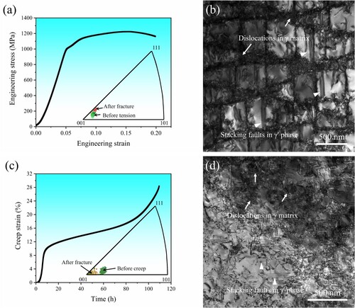
As the thrust-to-weight ratio of aircraft engines increases, the service condition of blades is becoming increasingly complex, which causes the diversity of service temperature and stress in different parts of the blade [Citation15,Citation16]. Therefore, decades of research have been spent investigating various deformation processes at different temperatures, including creep, tension, compression, fatigue, etc [Citation17,Citation18,Citation19,Citation20,Citation21,Citation22,Citation23]. Although these deformation conditions are different, stacking faults within γ′ phases are common typical defects at intermediate temperatures [Citation24,Citation25,Citation26,Citation27,Citation28]. As shown in Figure , at intermediate temperatures, Ni-based single crystal superalloys do have similar microstructures under different deformation conditions. Figure (a,b) describe the tensile curve and the microstructure of the experimental alloy after tension at 750 °C, respectively. Then, Figure (c,d) describe the tensile creep curve and the microstructure after tensile creep at 750 °C/750 MPa, respectively. It can be observed that they both show typical characteristics similar to previous research, having many stacking faults shearing into γ′ phases. In addition, there are a large number of dislocations in the γ matrix, all of which are a/2〈110〉 type dislocations [Citation29,Citation30]. However, previous studies mainly focused on the microstructure evolution in γ′ phases, while the movement of dislocations in the γ matrix was often overlooked [Citation31,Citation32]. Actually, the formation of stacking faults is closely related to dislocations in the γ matrix, that is, the reaction of dislocations to form stacking faults [Citation33,Citation34]. Therefore, it is difficult to evaluate which deformation mechanism dominates the deformation process.
Figure 1. At intermediate temperatures, Ni-based single crystal superalloys do have similar microstructures under different deformation conditions: (a) The tensile curve of the experimental alloy at 750 °C and the orientation before and after fracture; (b) The microstructure of the experimental alloy after tensile at 750 °C; (c) The tensile creep curve of the experimental alloy at 750 °C/750 MPa and the orientation before and after creep fracture; (d) The microstructure of the experimental alloy after tensile creep at 750 °C/750 MPa.
In superalloys, the matrix dislocation is a/2〈110〉 type dislocation originating from the activity of {111} 〈110〉 slip systems [Citation29,Citation30], and stacking faults originate from the activity of {111} 〈112〉 slip systems [Citation24,Citation25,Citation35]. Although both types of slip systems would be activated during deformation as shown in Figure (b,d), one type of slip system always dominates. During tensile deformation, single crystals rotate toward their slip direction, and the rotation direction of single crystals would vary depending on the slip system [Citation36]. Especially near the [001] orientation, the rotation process caused by the {111} 〈112〉 slip system is completely different from that caused by the {111} 〈110〉 slip system. Figure (a,c) also indicate that the orientation rotation pattern is different in tensile and tensile creep. Based on the orientation rotation behavior of several alloys, it can be determined {111} 〈112〉 slip system dominates the rotation process, which also means that the stacking fault shearing γ′ precipitate dominates the tensile creep process at intermediate temperature [Citation18,Citation36,Citation37,Citation38]. Therefore, the orientation rotation may also reveal the dominant mechanism during tensile deformation at intermediate temperatures. Here, the tensile deformation of the specimen with a certain deviation from [001] orientation is investigated by in-situ electron back-scattered diffraction (EBSD) at 750 °C. We systematically analyze the activity of slip systems and orientation rotation behavior at different tensile stages. Finally, we confirm that for tensile deformation at intermediate temperatures, {111} 〈110〉 slip system dominates the rotation process and the movement of matrix dislocations is the dominant deformation mechanism.
2. Materials and methods
A third-generation Ni-based single crystal superalloy was used in the present experiment, and the nominal composition was as follows(wt.%): 3.5Cr, 9Co, 1.5Mo, 6W, 8Ta, 4Re, 6Al, and the balance Ni. Further details about sample preparation are available in the Supplementary Material.
The uniaxial tension experiment was performed by a tensile testing machine mounted on a TESCAN S8000 field emission scanning electron microscope (SEM) equipped with EBSD detector (Oxford Symmetry Model) at 750 °C. Then the Euler angles were adopted to calculate the crystal orientation [Citation39]. Finally, ATEX-Software was used for the slip trace analysis [Citation40]. Further details about in-situ EBSD are also available in the Supplementary Material.
3. Results and discussion
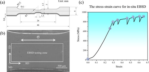
After the standard heat treatment, the sample rods were processed into the tensile sample for in-situ EBSD as shown in Figure (a). Figure (b) shows the macroscopic feature of the tensile specimen and the white rectangular area is selected for EBSD characterization during the tensile testing. The relationship between the tensile direction and EBSD coordinates is also described in Figure (b), in which the tensile loading direction is parallel to the rolling direction (RD). Therefore, the orientation change during the tensile process is determined by RD. Figure (c) is the stress–strain curve of the specimen for the in-situ EBSD testing. In order to reveal the rotation process of crystal orientation, several different deformation stages are selected for EBSD testing during the tensile process, including the initial stage (A), the elastic stage (B), the yield stage (C), and the plastic stage (D-H).
Figure 2. (a) Schematic diagram of the tensile specimen for in-situ EBSD analysis; (b) The macroscopic feature and the relationship between tensile direction and EBSD coordinates; (c) The stress-strain curve of the specimen for in-situ EBSD analysis.
The surface morphology evolution at different stages is displayed in Figure . Figure (a) shows the surface morphology of Stage A, which represents the state of the specimen before deformation. Figure (b) displays the surface morphology of the purely elastic strain stage, which corresponds to Stage B in Figure (c). Its surface morphology resembles Stage A, without obvious slip lines. When the specimen has just yielded at Stage C, some slip lines appear on the surface of the specimen as shown in Figure (c). These slip lines are straight and in the same direction. The angle between the slip line and the tensile direction is 49.78°. Slip trace analysis indicates that only a single slip system is activated and the slip plane is (111) plane. Stage D is in the plastic deformation zone as shown in Figure (c), and the surface morphology in Figure (d) indicates that there are still some straight slip lines along the (111) plane. However, the angle becomes 40.56°, which means that the orientation undergoes rotation during the plastic deformation [Citation41,Citation42].
Figure 3. Surface morphology evolution of the specimen at different deformation stages in Figure (c), and (a)-(h) represent stages A-H, respectively.
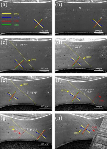
As the plastic deformation increases, the specimen undergoes a significant shrinkage in Figure (e). More interestingly, although these slip lines are still parallel to each other, they bend at the edge of the specimen. The middle part of these slip lines is still straight, and the angle decreases to 39.24°. The phenomenon of slip lines bending can also be observed in other research [Citation43,Citation44,Citation45,Citation46]. During the tension deformation, the ends of the specimen are restrained by the grips, and single crystals rotate toward the slip direction. However, the pure rotation only occurs in the central regions of the sample. To coordinate the reorientation in the center, the rotation and bending would exist simultaneously in other regions, which can cause the asynchronous of orientation rotation, leading to localized force inhomogeneity [Citation42]. At Stage F in Figure (f), the deformation is more severe, the bending degree of slip lines is also greater, and the included angle is smaller. In addition, another slip system is activated and the slip plane is (1
) plane. Subsequently, the specimen continues to deform under the action of double slips. As shown in Figure (g), the angle between the middle part of these slip lines along (111) plane and the tensile direction decreases to 33.43°, and those slip lines along (
1
) plane also becomes more. Finally, the specimen undergoes shear fracture along the (
1
) plane in Figure (h).
As shown in Figure , the angle between the slip line and the loading direction continuously decreases with increasing deformation, which indicates that orientation is also rotating. To clearly reveal the orientation rotation process of the specimen, the orientation evolution at different deformation stages is displayed in Figure and Table . The initial orientation of the specimen is [1.22, 9.74, −1.91], which is close to [010] orientation and has a deviation of 13.10°. The orientation at Stage B remains almost unchanged, which corresponds to the macrostructure under elastic strain in Figure (b). After yielding, the orientation rotation process is divided into two stages. First, from Stage C to Stage E, the orientation rotates from the initial orientation inside a standard three-dimensional triangle to the [Citation010]-[11] line. Then, from Stage F to Stage H, the orientation rotates towards the [111] pole along the [010]-[11
] line until the specimen fractures. The orientation after fracture is [2.22, 9.48, −2.26] and its deviation from [010] has also increased to 18.48°.
Figure 4. Orientation evolution of the specimen at different deformation stages and corresponding Schmid factors for twelve {111} 〈110〉 slip systems.
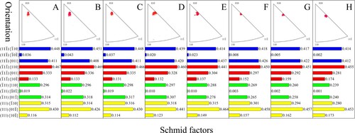
Table 1. Orientation of the specimen at different deformation stages.
The orientation change pattern indicates the rotation process originates from the activity of the {111} 〈110〉 slip system. Subsequently, Schmid factors for twelve {111} 〈110〉 slip systems are also calculated in Figure . Due to proximity to [010] orientation, there are multiple slip systems with large Schmid factors. Combining the slip trace analysis in Figure , the first active slip system is more likely to be (111) [01], while the second is (
1
) [110]. Subsequently, orientation rotation axis analysis was adopted to identify the current active slip system [Citation47,Citation48,Citation49]. The result of deviation angle (Δω) between experimental and analytical rotation axis of several {111} 〈110〉 slip systems further indicates that the first active slip system is (111) [01
] and the second is (
1
) [110] (see Supplementary Figure S1). From Stage C to Stage E, only single oriented slip lines appear on the surface of the specimen as shown in Figure (c–e). Therefore, the (111) [01
] slip system dominates the plastic deformation of Stages C to E, which causes the specimen rotates from initial orientation to the [010]-[11
] line. After Stage F, there are two active slip systems. Hence, the specimen rotates along the [010]-[11
] line until fracture, which occurs under the joint action of (111) [01
] and (
1
) [110] slip systems.
The standard stereographic projection would reveal the relationship between crystal orientation and the activity of slip systems. Then Figure (a) is the standard [010] stereographic projection of the cubic crystal system, and the specimen is located at the [010]-[110]-[11] standard stereographic triangle (Label I). The orientation rotation path of the specimen during in-situ EBSD testing is marked by the red dashed line as shown in Figure (b). To reveal the universality of the dominant deformation mechanism in tensile deformation at intermediate temperature, we statistically analyzed the orientation rotation of some alloys in Figure (b). The blue dashed line represents the rotation path of Ren
N4 during tensile deformation at 760 °C, in which the sample has rotated from the orientation near [110] to the vicinity of [12
] orientation [Citation50]. Zhang et al. [Citation51] also found that the grains in In 740H alloy also rotate during tensile deformation at 650 °C, and the rotation path of some grains is represented by the green dashed line in Figure (b). These grains are all located in the standard stereographic triangle and rotate toward the [010]-[11
] line. These rotation paths of these alloys are all consistent with the rotation behavior dominated by {111} 〈110〉slip systems. Figure (d) illustrates the orientation rotation in a standard stereographic triangle under {111} 〈110〉 slip system. In the [010]-[110]-[11
] standard stereographic triangle, [010], [110] and [11
] poles all have multiple activated slip systems, [010]-[110], [110]-[11
], and [010]-[11
] boundaries are regions of double slip, and the internal area of the triangle only has one activated slip system [Citation36]. Although these boundaries all belong to the double slip zone, three sides correspond to quite different double-slip orientations with differently active slip systems and corresponding dislocation reactions during tensile deformation: i.e. the critical double slip ([010]-[110]), the coplanar double slip ([110]-[11
]), and the conjugate double slip ([010]-[11
]) [Citation52,Citation53,Citation54]. For the specimen in the internal area of the triangle, as only the (111) [01
] slip system is activated, it will rotate toward [01
] direction, which is due to single crystals rotating toward their slip direction during tension deformation. When rotating to the [010]-[11
] boundary, the specimen is located at the junction of the [010]-[110]-[11
] (Label I) and the [010]-[01
]-[11
] (Label II) standard stereographic triangles. Therefore, the (
1
) [110] slip system in the [010]-[01
]-[11
] (Label II) standard stereographic triangle would also be activated. Then, the sample will rotate along the [010]-[11
] boundary under the action of conjugate double slip. Usually, when rotating to the position of [12
], the specimen no longer rotates, as the effects of the two slip systems cancel out each other. Therefore, the position of [12
] is the endpoint of the orientation rotation for the specimen in the internal area of the triangle. However, in this work, the orientation after fracture is [2.22, 9.48, −2.26], which deviates approximately 16.79° from [12
]. This was due to the asynchrony of the orientation rotation, which would cause nonuniform deformation and localized force inhomogeneity, leading to premature failure of the specimen [Citation42].
Figure 5. (a) The standard [010] stereographic projection; (b) The orientation rotation path of several alloys during tensile deformation at intermediate temperatures; (c) The orientation rotation path of several alloys during tensile creep at intermediate temperatures and high stress; (d) Illustration of orientation rotation in a standard stereographic triangle under {111} 〈110〉 slip; (e) Illustration of orientation rotation in a standard stereographic triangle under {111} 〈112〉 slip.
![Figure 5. (a) The standard [010] stereographic projection; (b) The orientation rotation path of several alloys during tensile deformation at intermediate temperatures; (c) The orientation rotation path of several alloys during tensile creep at intermediate temperatures and high stress; (d) Illustration of orientation rotation in a standard stereographic triangle under {111} 〈110〉 slip; (e) Illustration of orientation rotation in a standard stereographic triangle under {111} 〈112〉 slip.](/cms/asset/d63022c0-7123-4bcf-9970-9eafc1a444b6/tmrl_a_2304255_f0005_oc.jpg)
At intermediate temperatures, the orientation rotation path during tensile creep is different from that during tensile deformation. Figure (c) is the orientation rotation path of several alloys during tensile creep at intermediate temperatures and high stress. Although the alloy composition and creep conditions are different, their rotation paths follow the same law, that is samples in the vicinity of [010] orientation would rotate towards the [010] pole, while samples near [110] and [11] would rotate towards the [11
] pole [Citation18,Citation37,Citation38,Citation42]. These rotation paths of these alloys indicate the rotation behavior is dominated by the {111} 〈112〉slip system. Then the illustration of orientation rotation in a standard stereographic triangle under {111} 〈112〉 slip system is shown in Figure (e). Similar to Figure (d), [010], [110] and [11
] poles also have multiple activated slip system, and the [110]-[11
] boundary belongs to the coplanar double slip. Then the critical double slip includes the [010]-X and Y-[110] boundaries, and the conjugate double slip includes the [010]-Y and X-[11
] boundaries. The internal area in the standard stereographic triangle is the region of single slip, which is divided into two parts, [010]-X-Y and X-Y-[110]-[11
]. In [010]-X-Y region, (11
) [
21] is the dominant active slip system, but for X-Y-[110]-[11
] region, that is (111) [11
] slip system. In [010]-X-Y region, the specimen first rotates to the [010]-Y boundary. Then, the specimen will rotate to the [010] pole along the [010]-Y boundary under the action of conjugate double slip. But in X-Y-[110]-[11
] region, the specimen first rotates to the X-[11
] boundary and then rotates to the [11
] pole. Therefore, at intermediate temperatures, the tensile deformation is dominated by {111} 〈110〉 slip systems, while the tensile creep is dominated by {111} 〈112〉 slip systems.
As mentioned before, the extensive activation of matrix dislocations is a prerequisite for the formation of stacking faults [Citation33,Citation34]. Creep is the time-dependent deformation under constant stress and constant temperature, and the stress is lower than the yield strength [Citation55,Citation56]. At the initial stage of creep, the deformation mainly originates from the matrix dislocations. The longer deformation time makes it easier for matrix dislocations to react at γ/γ’ interface and form stacking faults, which leads to an increased impact of stacking faults on creep. However, compared to tensile creep, deformation behavior during the tensile is more sensitive to the strain rate rather than the loading time [Citation57,Citation58]. During tensile deformation, the continuously increasing stress and higher strain rate can lead to the formation of a large number of matrix dislocations in a short period. Therefore, the matrix dislocation would dominate the tensile deformation. Although there are still some stacking faults formed, they are not enough to affect the entire deformation process.
4. Conclusions
In conclusion, we studied the orientation rotation behavior of a Ni-based single crystal superalloy with a certain deviation from [010] orientation during tensile deformation at 750 °C by in-situ EBSD testing. We found the difference in the dominant deformation mechanisms between tensile deformation and tensile creep at intermediate temperatures. Although stacking faults are the most eye-catching deformation defects during both tensile and creep processes, the dislocation in the γ matrix can’t be ignored. Unlike the creep process dominated by stacking fault shearing γ’ phases, the dominant mechanism in tensile deformation is the movement of matrix dislocations. Additionally, the conclusions of this study may offer guidelines for designing superalloys servicing different usage conditions, based on which deformation mechanism dominates. For example, the superalloy used in rockets should place emphasis on strengthening the γ matrix; while for the superalloy used in turbine blades, the strengthening of both the γ matrix and γ’ phases cannot be ignored.
Supplemental Material
Download MS Word (187.6 KB)Disclosure statement
No potential conflict of interest was reported by the author(s).
Additional information
Funding
References
- Reed RC. The superalloys fundamentals and applications. Cambridge: Cambridge Univeisity Press; 2006.
- Ru Y, Hu B, Zhao W, et al. Topologically inverse microstructure in single-crystal superalloys: microstructural stability and properties at ultrahigh temperature. Mater Res Lett. 2021;9(12):497–506. doi:10.1080/21663831.2021.1982785
- Pollock TM, Tin S. Nickel-based superalloys for advanced turbine engines: chemistry, microstructure and properties. J Propul Power. 2006;22(2):361–374. doi:10.2514/1.18239
- Eris R, Akdeniz MV, Mekhrabov AO. Atomic size effect of alloying elements on the formation, evolution and strengthening of γ′-Ni3Al precipitates in Ni-based superalloys. Intermetallics. 2019;109:37–47. doi:10.1016/j.intermet.2019.02.017
- Reed RC, Rae CMF. 22 - Physical metallurgy of the nickel-based superalloys. In: Laughlin DE, Hono K, editor. Physical metallurgy (fifth edition). Oxford: Elsevier; 2014. p. 2215–2290.
- Heckl A, Neumeier S, Göken M, et al. The effect of Re and Ru on γ/γ′ microstructure, γ-solid solution strengthening and creep strength in nickel-base superalloys. Mater Sci Eng A. 2011;528(9):3435–3444. doi:10.1016/j.msea.2011.01.023
- Nembach E, Neite G. Precipitation hardening of superalloys by ordered γ′-particles. Prog Mater Sci. 1985;29(3):177–319. doi:10.1016/0079-6425(85)90001-5
- Owusu-Boahen K, Bamberger M, Dirnfeld SF, et al. Precipitation hardening in nickel based superalloys: effect of alloying. Mater Sci Technol. 1996;12(4):290–294. doi:10.1179/mst.1996.12.4.290
- Zhao W, Sun Z, Gong S. Vacancy mediated alloying strengthening effects on γ/γ′ interface of Ni-based single crystal superalloys: a first-principles study. Acta Mater. 2017;135:25–34. doi:10.1016/j.actamat.2017.05.074
- Chen K, Zhao LR, Tse JS. A first-principles survey of γ/γ′ interface strengthening by alloying elements in single crystal Ni–base superalloys. Mater Sci Eng A. 2004;365(1):80–84. doi:10.1016/j.msea.2003.09.009
- Benyoucef M, Clement N, Coujou A. TEM in situ straining of the MC2 superalloy at room temperature. Philos Mag A. 1995;72(4):1043–1056. doi:10.1080/01418619508239952
- Zhao Y, Li N, Wang L, et al. High-temperature creep-induced site occupation evolution in the γ′ lattice in a Ru-bearing Ni-based superalloy. Mater Res Lett. 2023;11(10):888–895. doi:10.1080/21663831.2023.2254910
- Smith TM, Zarkevich NA, Egan AJ, et al. Utilizing local phase transformation strengthening for nickel-base superalloys. Commun Mater. 2021;2(1):106. doi:10.1038/s43246-021-00210-6
- Smith TM, Esser BD, Antolin N, et al. Phase transformation strengthening of high-temperature superalloys. Nat Commun. 2016;7:13434. doi:10.1038/ncomms13434
- Dye D, Ma A, Reed R. Numerical modelling of creep deformation in a CMSX-4 single crystal superalloy turbine blade. Superalloy. 2008;2008:911–919.
- Rezazadeh Reyhani M, Alizadeh M, Fathi A, et al. Turbine blade temperature calculation and life estimation - a sensitivity analysis. Propuls Power Res. 2013;2(2):148–161. doi:10.1016/j.jppr.2013.04.004
- Barba D, Alabort E, Pedrazzini S, et al. On the microtwinning mechanism in a single crystal superalloy. Acta Mater. 2017;135:314–329. doi:10.1016/j.actamat.2017.05.072
- Li YM, Tan ZH, Wang XG, et al. Stress rupture anisotropy of a Ru-containing fourth-generation single crystal superalloy at 760 °C and 1100 °C. Mater Sci Eng A. 2022;856:144006. doi:10.1016/j.msea.2022.144006
- Ding Q, Bei H, Yao X, et al. Temperature effects on deformation substructures and mechanisms of a Ni-based single crystal superalloy. Appl Mater Today. 2021;23:101061. doi:10.1016/j.apmt.2021.101061
- Yang W, Qu P, Liu C, et al. Temperature dependence of compressive behavior and deformation microstructure of a Ni-based single crystal superalloy with low stacking fault energy. Trans Nonferrous Met Soc China. 2023;33(1):157–167. doi:10.1016/S1003-6326(22)66097-7
- Zhang Y, Wang X, Li J, et al. The low-cycle fatigue deformation mechanisms of two single crystal superalloys at room temperature and 600 °C. Scripta Mater. 2019;171:122–125. doi:10.1016/j.scriptamat.2019.06.033
- Wang XG, Liu JL, Liu JD, et al. Dependence of stacking faults in gamma matrix on low-cycle fatigue behavior of a Ni-based single-crystal superalloy at elevated temperature. Scripta Mater. 2018;152:94–97. doi:10.1016/j.scriptamat.2018.04.020
- Tan Z, Wang X, Pang J, et al. Pore-induced defects during thermo-mechanical fatigue of a fourth-generation single crystal superalloy. Mater Res Lett. 2023;11(8):678–687. doi:10.1080/21663831.2023.2223558
- Chen QZ, Knowles DM. Mechanism of 〈112〉/3 slip initiation and anisotropy of γ′ phase in CMSX-4 during creep at 750 °C and 750 MPa. Mater Sci Eng A. 2003;356(1-2):352–367. doi:10.1016/s0921-5093(03)00148-5
- Knowles DM, Gunturi S. The role of 〈112〉{111} slip in the asymmetric nature of creep of single crystal superalloy CMSX-4. Mater Sci Eng A. 2002;328(1):223–237. doi:10.1016/S0921-5093(01)01688-4
- Viswanathan GB, Shi R, Genc A, et al. Segregation at stacking faults within the γ′ phase of two Ni-base superalloys following intermediate temperature creep. Scripta Mater. 2015;94:5–8. doi:10.1016/j.scriptamat.2014.06.032
- Yuan Y, Gu YF, Osada T, et al. Deformation mechanisms in a new disc superalloy at low and intermediate temperatures. Scripta Mater. 2012;67(2):137–140. doi:10.1016/j.scriptamat.2012.03.042
- Gao Z, Zhang P, Li J, et al. Tunning the tensile deformation behavior and mechanism of nickel-based superalloy CM247LC by adjusting ageing treatment. Mater Res Lett. 2023;11(12):1013–1021. doi:10.1080/21663831.2023.2276340
- Condat M, Décamps B. Shearing of γ′ precipitates by single a/2<110〉 matrix dislocations in a γ/γ′ Ni-based superalloy. Scr Metall. 1987;21(5):607–612. doi:10.1016/0036-9748(87)90369-3
- Décamps B, Morton AJ, Condat M. On the mechanism of shear of γ′ precipitates by single (a/2)<110〉 dissociated matrix dislocations in Ni-based superalloys. Philos Mag A. 1991;64(3):641–668. doi:10.1080/01418619108204866
- Bai JM, Zhang HP, Liu JT, et al. Temperature dependence of tensile deformation mechanisms in a powder metallurgy Ni–Co–Cr based superalloy with Ta addition. Mater Sci Eng A. 2022;856:143965. doi:10.1016/j.msea.2022.143965
- Wang XG, Liu JL, Jin T, et al. The effects of ruthenium additions on tensile deformation mechanisms of single crystal superalloys at different temperatures. Mater Des. 2014;63:286–293. doi:10.1016/j.matdes.2014.06.009
- Drew GL, Reed RC, Kakehi K, et al., editors. Single crystal superalloys: the transition from primary to secondary creep. Superalloys 2004; 2004. pp. 127–136.
- Qu P, Yang W, Qin J, et al. Reveal the stacking fault shearing mechanism by its annihilation process in Ni-based single crystal superalloys. Mater Charact. 2021;180:111419. doi:10.1016/j.matchar.2021.111419
- Zhang P, Li J, Yuan Y, et al. Correlation the 〈112〉{111} slip with high-temperature tension/compression asymmetry in the single-crystal nickel-based superalloy PWA1483. Mater Res Lett. 2023;11(6):399–406. doi:10.1080/21663831.2023.2166432
- MacKay RA, Maier RD. The influence of orientation on the stress rupture properties of nickel-base superalloy single crystals. Metall Trans A. 1982;13(10):1747–1754. doi:10.1007/BF02647830
- Qu P, Yang W, Liu C, et al. Creep anisotropy dominated by orientation rotation in Ni-based single crystal superalloys at 750 °C/750 MPa. J Mater Sci Technol. 2024;186:91–103. doi:10.1016/j.jmst.2023.10.055
- Li Y, Wang L, Zhang G, et al. Creep anisotropy of a 3rd generation nickel-base single crystal superalloy at 850 °C. Mater Sci Eng A. 2019;760:26–36. doi:10.1016/j.msea.2019.05.075
- Adams BL, Kalidindi SR, Fullwood DT. Chapter 2 - tensors and rotations. In: Adams BL, Kalidindi SR, Fullwood DT, editor. Microstructure sensitive design for performance optimization. Boston: Butterworth-Heinemann; 2013. p. 23–44.
- Beausir B, Fundenberger JJ. Analysis tools for electron and X-ray diffraction, ATEX-software. Eu, Université de Lorraine-Metz, France; 2017.
- Han JH, Kim DI, Jee KK, et al. In-situ orientation rotation behavior study during tensile deformation of aluminum single crystal and polycrystal. Mater Sci Forum. 2004: 449–452: 593-596. doi:10.4028/www.scientific.net/MSF.449-452.593
- Qu P, Yang W, Liu C, et al. The asynchrony of orientation rotation at 750 °C/750 MPa creep in a [011]-oriented Ni-based single crystal superalloy. Mater Sci Eng A. 2023;869:144823. doi:10.1016/j.msea.2023.144823
- Chen J, Lu J, Cai W, et al. In-situ study of adjacent grains slip transfer of Inconel 718 during tensile process at high temperature. Int J Plast. 2023;163:103554. doi:10.1016/j.ijplas.2023.103554
- Guo G, Jiang W, Liu X, et al. In-situ SEM-EBSD investigation of the low-cycle fatigue deformation behavior of Inconel 718 at grain-scale. J Mater Res Technol. 2023;24:5007–5023. doi:10.1016/j.jmrt.2023.04.143
- Li F, Jiang W, Lu J, et al. In situ EBSD study of formation and propagation of deformation bands in a single-crystal superalloy during tensile deformation. J Mater Sci. 2023;58(26):10764–10781. doi:10.1007/s10853-023-08681-3
- Ren X, Lu J, Zhou J, et al. In-situ fatigue behavior study of a nickel-based single-crystal superalloy with different orientations. Mater Sci Eng A. 2022;855:143913. doi:10.1016/j.msea.2022.143913
- Yang B, Shi C, Lai R, et al. Identification of active slip systems in polycrystals by Slip Trace - Modified Lattice Rotation Analysis (ST-MLRA). Scripta Mater. 2022;214:114648. doi:10.1016/j.scriptamat.2022.114648
- Yang B, Shi C, Ye X, et al. Underlying slip/twinning activities of Mg-xGd alloys investigated by modified lattice rotation analysis. J Magnes Alloy. 2023;11(3):998–1015. doi:10.1016/j.jma.2021.06.008
- Gu T, Xu Y, Gourlay CM, et al. In-situ electron backscatter diffraction of thermal cycling in a single grain Cu/Sn-3Ag-0.5Cu/Cu solder joint. Scripta Mater. 2020;175:55–60. doi:10.1016/j.scriptamat.2019.09.003
- Miner RV, Voigt RC, Gayda J, et al. Orientation and temperature dependence of some mechanical properties of the single-crystal nickel-base superalloy René N4: Part I. Tensile behavior. Metall Trans A. 1986;17(3):491–496. doi:10.1007/BF02643955
- Zhang W, Lu J, Wang J, et al. In-situ EBSD study of deformation behavior of Inconel 740H alloy at high-temperature tensile loading. J Alloys Compd. 2020;820:153424. doi:10.1016/j.jallcom.2019.153424
- Li XW, Wang ZG, Li SX. Cyclic deformation behavior of double-slip-oriented copper single crystals I: coplanar double slip orientation on 011-11 side of the stereographic triangle. Mater Sci Eng A. 1999;260(1):132–138. doi:10.1016/S0921-5093(98)00974-5
- Li XW, Wang ZG, Li SX. Cyclic deformation behavior of double-slip-oriented copper single crystals: II. Critical double slip orientation on 001/011 side of the stereographic triangle. Mater Sci Eng A. 1999;265(1):18–24. doi:10.1016/S0921-5093(99)00008-8
- Li XW, Wang ZG, Li SX. Cyclic deformation behavior of double-slip-oriented copper single crystals III: conjugate double slip orientation on 001–11 side of the stereographic triangle. Mater Sci Eng A. 1999;269(1):166–174. doi:10.1016/S0921-5093(99)00154-9
- Kumar N, Joseph AS, Mehrotra P, et al. An improved dislocation density reliant model to address the creep deformation of reduced activation ferritic martensitic steel. Forces in Mechanics. 2022;9:100117. doi:10.1016/j.finmec.2022.100117
- Yadav SD, Sonderegger B, Stracey M, et al. Modelling the creep behaviour of tempered martensitic steel based on a hybrid approach. Mater Sci Eng A. 2016;662:330–341. doi:10.1016/j.msea.2016.03.071
- Kumar N, Yadav SD. Microstructure Based Flow Stress Modelling of Superalloy 718. Solid State Phenomena. 2023;353:103–108. doi:10.4028/p-ALg9Hs
- Joseph AS, Gupta P, Kumar N, et al. An advanced dislocation density-based approach to model the tensile flow behaviour of a 64.7Ni–31.96Cu alloy. Philos Mag. 2022;102(15):1481–1504. doi:10.1080/14786435.2022.2056645