
 ?Mathematical formulae have been encoded as MathML and are displayed in this HTML version using MathJax in order to improve their display. Uncheck the box to turn MathJax off. This feature requires Javascript. Click on a formula to zoom.
Abstract
Peripheral nerve injury has troubled clinical doctors for many years. To obtain better function recovery of peripheral nerve repair at the base of hollow nerve guidance conduit (NGC), many NGCs with fillers were developed in the application of tissue-engineered nerve graft. In this study, expanded 3D nanofibre sponge scaffolds with orientation and porosity were first fabricated by electrospinning and gas-foaming technique. Polylactic acid (PLA)/silk fibroin nanofibre sponge scaffolds were prepared as filler to construct 3D nanofibre sponges containing NGC (SNGC). SNGC could promote the proliferation of Schwann cells compared with the hollow NGC in vitro. The results of animal experiments confirm that SNGC can significantly promote peripheral nerve function recovery from histology and function evaluation. In conclusion, we design a new method to construct a 3D scaffold containing NGC with orientation and porosity. The application of this 3D scaffold material has good prospects in future peripheral nerve repair.
Introduction
Trauma-induced peripheral nerve injury is a common clinical problem that often leads to permanent loss of motor and sensory function, causing immense trouble for families and society [Citation1–4]. Peripheral nerve injury has a certain capability to regenerate, but many limitations in the process of nerve regeneration often lead to poor recovery [Citation5]. Therefore, surgical treatment is generally required after peripheral nerve injury. For the small nerve defect, epicardial or perimamial anastomosis is used. However, these surgical procedures often lead to formation of scars and neuroma [Citation5]. Jiang et al. [Citation6,Citation7] uses chemotaxis theory to develop chitosan conduit to suture a neural stump with a small gap (2 mm); this suture technique reduces the operation time while avoiding the formation of scars and neuroma, and the restoration effect is better than that of epineurial neurorrhaphy.
However, for serious nerve injury with large gaps, nerve grafts must be implanted to fill the nerve defect [Citation8,Citation9]. Autologous nerve transplantation is considered as the gold standard for peripheral nerve repair because it can provide the basement membrane tube needed for the growth of axons with small immune rejection [Citation5,Citation8]. Autologous nerve transplantation still has many problems, such as insufficient sources, difficulty in meeting the requirements of long-term neurological deficits, new lesions and loss of function left after the donor site is removed, and artificially formed traumatic neuroma, sensory disturbance and loss of function [Citation10]. Therefore, the development of artificial nerve grafts is considered as a promising alternative to autologous nerve grafts [Citation11].
Tissue-engineered nerve graft serves as a promising alternative autograft to bridge the peripheral nerve gap and promote nerve regeneration [Citation12,Citation13]. Tissue-engineered nerve grafts generally consist of scaffolds, seed cells and growth factors. The scaffolds promoting cell adhesion and directs axon growth play the most significant role in tissue engineering. A series of biological material-based nerve grafts has been developed in the laboratory and clinic, mainly in the form of nerve conduits with different material [nerve guidance conduit (NGCs)] [Citation14–16]. The degradable nerve conduit material mainly includes natural macromolecules such as collagen, chitosan, silk fibroin (SF), and synthetic polymer materials such as polylactic acid (PLA), poly(lactic-co-glycolic acid) (PLGA) and polycaprolactone (PCL) [Citation16,Citation17].
To maximally promote nerve regeneration, researchers have developed many NGCs with fillers, such as multichannel scaffold [Citation18,Citation19], aligned fibre membrane [Citation20,Citation21], hydrogel [Citation22–24] and sponge-like porous scaffold [Citation25]. These fillers mimic the extracellular matrix (ECM) structure, providing a neural regeneration microenvironment that promotes axon regeneration.
Electrospinning is a simple and versatile technology to produce nanofibres with controllable diameter, which can mimic the hierarchical structure of the ECM. Thus, with the advantages of distinct small fibre diameter, large specific surface area, and high porosity, electrospinning has been a commonly used method for preparing tissue engineering scaffolds, including wound dressing [Citation26,Citation27], cartilage tissue engineering [Citation28,Citation29], tendon tissue engineering [Citation30,Citation31], neural tissue engineering [Citation32,Citation33] and others. Although the electrospinning nanofibre scaffolds can provide special porous nanostructures that simulate the ECM, limitations prevent them from becoming the ideal scaffold for tissue engineering because electrospinning typically produces compact 2D nanofibre membranes, which may restrict cellular infiltration and proliferation. To overcome this obstacle, several attempts have been made into 3D electrospun nanofibre scaffolds [Citation34,Citation35], and they can provide a 3D microenvironment for cell growth and infiltration. If properly designed, 3D electrospinning scaffold could be an ideal candidate for nerve tissue repair.
In this study, we constructed a compound scaffold with oriented 3D SF/PLA nanofibre sponge filler and chitosan conduit sheaths. The orientation 3D nanofibre sponge filler was fabricated by combination of electrospinning and gas-foaming technologies. The microstructure of the scaffolds was evaluated using SEM. The SCs were cultured in the 3D SF/PLA nanofibre sponge to evaluate their effect on cell attachment and proliferation. The 3D SF/PLA nanofibre sponge was then prefilled in the NGC to bridge a 10 mm long sciatic nerve defect in rats. Recovery of nerve and muscle function was evaluated by histology, electrophysiology and catwalk system.
Materials and methods
Fabrication of SF/PLA nanofibre membranes
The regenerated SF was prepared through the previously reported method [Citation34]. The electrospinning solution was prepared by dissolving the regenerated SF and PLA (w:w = 2:3) in HFIP with the concentration of 12% (w:v) and stirring at room temperature for 4 h until homogeneous. Then, the SF/PLA solution was electrospun by a setup that consisted of a high-voltage power supply and a digitally controlled syringe pump. The electrospinning solution was placed in a 20 ml plastic syringe equipped with a stainless-steel needle. The flow rate and applied voltage were set at 2 ml/h and 15 kV, respectively, and the distance between the needle and collector was 10 cm. The electrospun nanofibres were collected on a plate (30 cm × 30 cm) covered with aluminium foil. Finally, the collected SF/PLA nanofibre membrane was placed in vacuum overnight to remove the residual solvent.
Fabrication and characterization of 3D scaffold
Chitosan conduits were prepared as described previously [Citation14]. (Please refer to Chinese patent ZL 01136314.2 for the Supplementary data technical details). The 3D nanofibre sponges were prepared by a gas-foaming technique previously reported [Citation32]. First, the prepared SF/PLA nanofibre membrane was cut into 2 × 15 mm strips. Then, the strips were expanded by immersion in 100 ml fresh prepared sodium borohydride solution (1 mol/l) for 30 min at room temperature. Next, the expanded scaffolds were thoroughly rinsed five times with ultra-pure water and freeze dried to obtain the electrospun nanofibre sponges. Finally, nanofibre sponges were implanted into chitosan conduits to form the 3D scaffold.
The porosity of the nanofibre sponges was calculated according to the change of volume of nanofibre scaffolds before and after expansion. Porosity was calculated with the following equation:
where ε is porosity, V is the volume of PLA/SF nanofibre scaffold, V0=m0/ρ0 is the calculated volume of bulk PLA/SF material, m0 is the mass of bulk PLA/SF material, and ρ0 is the density of bulk PLA/SF material.
Culture and proliferation assay of schwann cell
Three-day-old Sprague–Dawley (SD) mice were used to culture Schwann cell. The sciatic nerve was completely cut and its epicardium was removed under a microscope. It was collected in a small glass bottle digested with 0.2% NB4 collagenase for 10 min at 37 °C. Digestion and centrifuge were terminated at room temperature. Appropriate Schwann cell culture medium (10% fetal bovine serum, 1% penicillin/streptomycin and 10−2 M/ml Forskolin) was added to resuspend the cells. Schwann cell was seeded in cell culture flask and incubated in a carbon dioxide incubator. After incubation for 48 h, 1 ml 0.05% NB4 collagenase was added to digest the Schwann cell. Proper Schwann cell culture medium was added to resuspend the cells and blow evenly, and then seeded in 96-well plates for CCK8 assay. After culture for 1, 3 and 5 days, 10 μL of CCK solution was added to each well. The absorbance at 450 nm was measured with a microplate reader.
Five days after cultivation, nanofibre sponges containing NGC (SNGC) was fixed with 2.5% glutarin for 30 min. The sample was dehydrated in gradient alcohol (30–100%), and then dried by vacuum dryer and recorded with SEM.
Surgical process
SD rats aged 8 weeks, weighing 200–220 g, were anaesthetized with 3% sodium pentobarbital solution (30 mg/kg body weight) by intraperitoneal injection. The rats were randomly divided into three groups: autograft, hollow NGC and SNGC. Once anesthesia took effect, the sciatic nerve of the right hind limbs of the rats was exposed. A part of the sciatic nerve was cut and removed to leave a 10 mm gap defect between the nerve stumps. The nerve stump was bridged with tissue engineering nerve graft under the microscope by 10–0 suture, and the wound was closed completely. Upon waking, the rats were reared in groups for automatic supply of food and drinking water and 12-h light/dark natural circulation in a feeding environment.
Evaluation of nerve regeneration
Twelve weeks after surgery, nerve graft in all groups was collected and fixed in 2.5% glutaraldehyde immediately for 12 h, transferred to 1% osmium tetroxide solution for 4 h, and dehydrated in increasing concentrations of acetone (from 30% to 100%). After dehydration, specimens were embedded in Epon 812 epoxy resin and cut into 700 and 70 nm thick sections. The 700 nm thick sections were stained with 1% toluidine blue solution observed under an optical microscope. The 70 nm thick sections were stained with 3% uranyl acetate-lead citrate and recorded under a transmission electron microscope. Image Pro Plus software was used to calculate remyelinated nerve fibre diameter and myelin sheath thickness.
Muscle evaluation
Twelve weeks after surgery, the gastrocnemius muscles of all groups were cut off immediately from the surgical and contralateral side of hindlimbs to calculate wet weight ratios, and were then fixed in 4% paraformaldehyde at 4 °C for 12 h. Embedded by paraffin, the muscle samples were cut into 7 μm thick sections, and then subjected to Masson trichrome staining. For each sample, photos were taken from three random fields and quantitatively analysed with Image Pro Plus.
Electrophysiological evaluation
Twelve weeks after surgery, the rats in each group were weighed and anaesthetized with sodium pentobarbital. The gastrocnemius and sciatic nerve were exposed for electrophysiological evaluation. Medlec Synergy electrophysiological system (Oxford Instrument Inc., Abingdon, UK) was used to check the electrical activity of all groups. The stimulating electrodes were placed at the proximal and distal nerve graft, and the recording electrodes were placed on the gastrocnemius muscles. The stimulation current was adjusted to 0.09 mA with stimulation time of 0.1 ms. After the baseline was stabilized, the stimulation signal was recorded.
Sciatic nerve index analysis
CatWalk XT gait analysis system (Noldus, Wageningen, Netherlands) was applied to detect motor function recovery of rats at 4, 8 and12 weeks after operation. The width of walking route was adjusted based on the body size of the rats. Camera position and set-up software parameters were adjusted. The rats were trained before the test to make them run continuously, and then CatWalk XT gait analysis system automatically recorded the movement parameters.
The sciatic function index (SFI) was calculated using the following Brain formula: SFI = 109.5(ETS − NTS)/NTS − 38.3(EPL − NPL)/NPL + 13.3(EIT − NIT)/NIT − 8.8.
Data analysis
All numerical data are reported as the mean ± standard deviation. The statistical analysis was performed with analysis of variance (ANOVA). Differences were considered statistically significant when p values <.05. All the data were analyzed using SPSS 17.0 (IBM).
Results
Evaluation of characterization of 3D nanofibre sponge
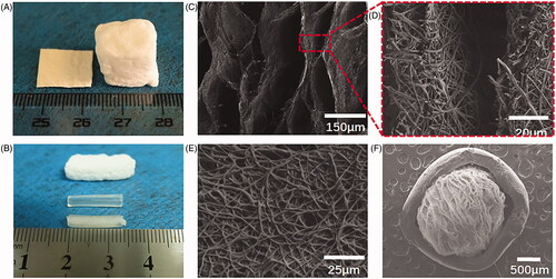
The SF/PLA electrospinning nanofibre membrane was successfully expanded in the third dimension (). The porosity of the scaffold was significantly increased compared with the 2D nanofibre membrane. demonstrates the 3D scaffold layered structure with the interlayer spacing between 20 and 150 µm. The wall of each layer is composed of the randomly arranged nanofibres with diameter of 50–500 nm, and the thickness of the layer walls were between 10 and 20 µm. The 3D scaffold completely maintains its nanofibre structure during the expansion process. The unique oriented layer and random nanofibre structure would be an excellent scaffold for peripheral nerve regeneration. To insert the 3D nanofibre scaffold into the chitosan nerve conduit, the 2D nanofibre membrane was pre-cut into 2 × 15 mm strips before foam expansion. The degree of expansion was precisely controlled by adjusting the foaming time to adapt to the size of the nerve guide.
Figure 1. Morphology characterization of SF/PLA 3D nanofibre scaffold (A, B). General view of SF/PLA 3D nanofibre scaffold. (C–F) SEM of SF/PLA 3D nanofibre scaffold.
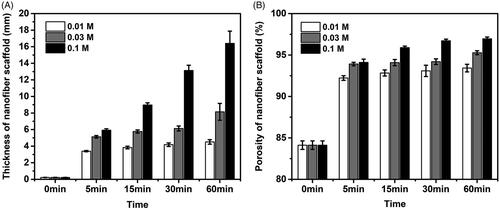
After the treatment of NaBH4 aqueous solutions, electrospun PLA/SF nanofibre membranes were successfully expanded in the third dimension. The thickness of the expanded scaffold increased with the increase of processing time and the increase of NaBH4 concentration (), and the thickness of nanofibre could reach the maximum 16.47 mm from 0.22 mm after 60 min treatment with 0.1 M NaBH4 aqueous solution. Similarly, the porosity of the expanded nanofibre scaffold also increased with increasing processing time and increasing concentration of NaBH4 (). The porosity of the nanofibre scaffold increased to maximum 96.98% (60 min in 0.1 M NaBH4 aqueous solution) from a baseline porosity of 84.12% (initial nanofibre membrane). The expanding degree of nanofibre scaffold can be controlled by adjusting the concentration of NaBH4 and processing time reasonably.
Figure 2. Expansion and characterization of the nanofibre scaffolds. (A) Thickness of the expanded PLA/SF nanofibre membranes after immersing in 0.01 M, 0.03 M, 0.01 M NaBH4 aqueous solutions for 0 min, 5 min, 15 min, 30 min and 60 min. (B) Corresponding porosities of the expanded PLA/SF nanofibre membranes after immersing in 0.01 M, 0.03 M, 0.01 M NaBH4 aqueous solutions for 0 min, 5 min, 15 min, 30 min and 60 min.
3 D nanofibre sponge promotes schwann cell proliferation
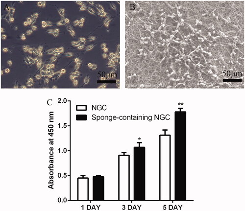
The SEM image shows the adhesion of Schwann cells on a 3D scaffold (). On the first day of Schwann cell culture, no statistical difference was noted between the two groups. On day 3, the SNGC group was higher than the NGC group, and a statistical difference was noted between the two groups (p < .05). On day 5, the SNGC group was significantly higher than the NGC group, and a statistical difference was noted between the two groups (p < .01) ().
Figure 3. (A) Images of rat primary SCs cultured in medium. (B) SEM of SCs cultured in SF/PLA 3D nanofibre scaffold. (C) Date analysis of the SC proliferation with CCK8.
Regenerated nerve assessment
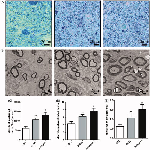
shows the cross-section of regenerated nerve fibres at 12 weeks after surgery under a light microscope and transmission electron microscopy (TEM). is semi-thin section toluidine blue staining analysis of the number of myelinated nerve fibres in the regenerated tissue. The density of nerve fibre in the SNGC group was higher than that in the hollow NGC group, and the difference was statistically significant. Nevertheless, the autograft group still showed the best regenerative effect among all groups. TEM images were used to calculate the diameter and myelin sheath thickness of the myelinated nerve fibres (). Statistical analysis confirmed that the diameter of the myelinated nerve in the SNGC group was higher than that in the hollow NGC group, and the thickness of the myelin sheath was larger. However, autograft works best in all groups.
Figure 4. Evaluation of regenerated nerve fibres at 12 weeks after surgery. Toluidine blue-stained transverse sections (A); TEM images of the regenerated sciatic nerve (B); Density of myelinated axons (C); Diameters of myelinated axons (D); Thickness of myelin sheath (E). **p < .01 versus NGC group; #p < .05 versus SNGC group; ##p < .01 versus SNGC group.
Evaluation of muscle recovery of target organs
Twelve weeks after surgery, the operative and contralateral gastrocnemius muscles of all rats were isolated. shows the general observation image of isolated gastrocnemius and varying degrees of atrophy in all groups.
Figure 5. Gastrocnemius muscle at 12 weeks after implantation. (A) Gross images of gastrocnemius muscles. (B) Masson’s trichrome staining images of the transverse sections of gastrocnemius muscles. Statistical analysis of the gastrocnemius muscle wet weight ratio (C) and cross section of muscle fibre (D). **p < .01 versus NGC group; #p < .05 versus SNGC group.
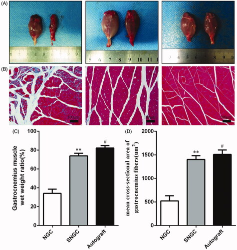
Masson muscle trichrome staining was performed on the cross-section of the gastrocnemius, and the cross sections of all muscle fibres in each group were observed under an optical microscope (). shows the wet weight ratios of muscles and mean cross sectional area of muscle fibre of the three groups. The SNGC group was similar to the autograft group. The hollow NGC group was worse than the SNGC group and autograft group with statistical differences, which is consistent with the SFI results.
Electrophysiological evaluation
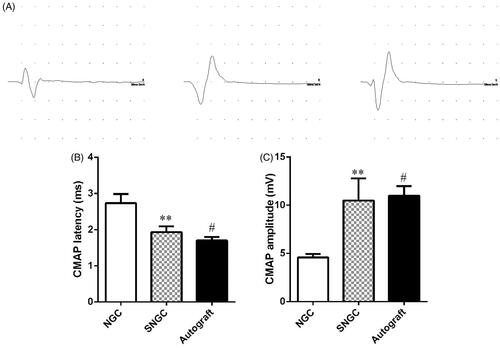
Electromyogram was used to record the electrophysiological properties of nerves and muscles by stimulating nerves clinically. The magnitude of compound muscle action potentials (CMAP) is dictated by the number of muscle fibres, and the latency is determined by the thickness of the myelin sheath and the diameter of the axon. shows typical CMAP response waves in three different groups at 12 weeks after surgery. The CMAP amplitude of the SNGC group was significantly higher than that of the hollow NGC group, but it was still lower than that of the autograft group (). Moreover, the latency of the SNGC group was similar to that of the autograft group, which was significantly lower than that of the hollow group, and the difference was statistically significant ().
Figure 6. Electrophysiological examinations at 12 weeks after implantation. (A) Representative CMAP recordings in each group. Statistical analysis of CMAP amplitude (B) and CMAP latency (C) detected in each group. **p < .01 versus NGC group; #p < .05 versus SNGC group.
Recovery of sciatic nerve function index
shows the use of the CatWalk gait analysis system to assess the recovery of motor function. First, the system provides qualitative indicators of motor function based on walking records, including standing time and pressure strength of the limbs (). Next, the percentages of standing/swing time are compared. The SNGC group showed a similar percentage to the autograft group, which was higher than the hollow NGC group (), indicating that motor function recovery of SNGC group was better than the control group.
Figure 7. Motor functional recovery at 12 weeks by CatWalk gait analysis. (A) Representative CatWalk analysis trace and 3D plantar pressure distribution of RH (injured) and LH (contralateral) from three different groups. Statistical analysis of the mean stand time ratio (B) and SFI values (C). **p < .01 versus NGC group; #p < .05 versus SNGC group; ##p < .01 versus SNGC group.
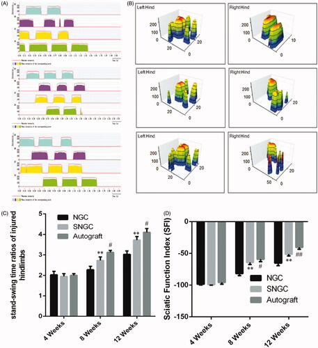
SFI was used to evaluate motor function recovery. At 4 weeks after surgery, no significant difference in SFI was noted between the groups. At 8 weeks after surgery, the SFI in the SNGC group was significantly better than that in the hollow NGC group. The difference was statistically significant. However, the effect was still not as good as that of the autograft group. However, 12 weeks after surgery, the SNGC group was close to the SFI in the autograft group, which was significantly better than hollow NGC group ().
Discussion
Peripheral nerve segment defects remain problems in clinical practice, although various biological materials including natural or synthetic polymers have been used to repair peripheral nerve injury [Citation16,Citation17]. However, the effect on nerve regeneration on clinical requirements remains unsatisfactory. Many studies have used neural catheter implants to simulate ECM structures [Citation19,Citation23–25].
Electrospinning nanofibres have shown great promise as regenerative medicine scaffold due to their architecture and fibre size, which are similar to that of ECM. The nanotopographic cues rendered by electrospun nanofibres can guide cellular morphology, migration and differentiation. Thus, precisely designed electrospinning nanofibre scaffolds have excellent potential for use in peripheral nerve repair. However, electrospinning generally produces the densely packed nanofibre membrane with small pore size, which lacks the typical microstructure of nerve tissue and limited the cell infiltration and 3D tissue formation. Increasing evidence has demonstrated that the microstructure of the nerve scaffold influences cellular organization and proliferation, which are important for the construction of a functional material for nerve repair [Citation36]. Therefore, some researchers have prepared the 3D sponge as NGC filler via dispersion and freeze-drying method [Citation25].
The SNGC could provide a 3D microenvironment with macropores for SC growth and infiltration. They could also biomimic the endoneurial-like architecture of nerve fascicles, but this type of non-oriented 3D scaffold lacks directional cues that are critical to the regeneration of organized nervous tissue. Preparation of oriented 3D scaffold remains a significant challenge. Here, we constructed a compound scaffold with oriented 3D nanofibre sponge filler and chitosan conduit sheaths. The chitosan conduit was used to bridge the peripheral nerve gap scaffold to provide long protection for regenerating axons from compression stress. SF and PLA with good biocompatibility and biodegradability were used to fabricate nanofibre sponges. First, SF/PLA nanofibre membranes were prepared and crosslinked. Then, the nanofibre membrane was cut into strips of suitable size and expanded in NaBH4 solution to generate nanofibre sponges. The expanded nanofibre scaffold had significantly higher porosity than traditional 2D nanofibre membranes. According to the SEM images, the expanded scaffold had an oriented layered structure with gap widths, which were in the range of 20–150 µm and provided oriented guidance cues for cell seeding and proliferation. The wall of the layer composed of random nanofibre with diameter range from 50 to 500 nm, which provided a suitable surface for cell adhesion and migration. Interconnected micropores and fibre network also helped in the transport of the necessary oxygen and nutrients during cell growth. In general, the 3D nanofibre scaffold with a luminal longitudinally aligned layer mimicked the microstructure of nerve tissue, established a favourable microenvironment for nerve regeneration, regulated cellular physiological activities, and supported and organized infiltrating and proliferating cells.
When cultured in the SNGC, the CCK8 results show that the proliferation capability of Schwann cells was better than that of the hollow NGC group.
Twelve weeks postoperatively, although all groups of regenerative nerve achieved reconnection with distal target organs, differences in functional recovery were noted. Functional evaluation indicators are as follows: electrophysiological tests showed that the amplitude and latency of CMAP in the SNGC group were similar to those in the autograft group. The amplitude of CMAP was positively correlated with the number of regenerated nerve fibres, diameter of nerve fibre and thickness of myelin sheath in the redominated target muscles. The results of the CMAP amplitude suggest that the SNGC group actively supported nerve fibre growth to redominate the target muscles. The latency of CMAP was negatively correlated with the number of regenerated nerve fibres, diameter of nerve fibres and thickness of the myelin sheath.
Histological evaluation of toluidine blue staining and TEM further confirmed the results. After sciatic nerve injury, atrophy occurs because of denervation of the gastrocnemius muscle. The degree of gastrocnemius atrophy can determine whether regenerating nerves can regain control of the target muscle. Meanwhile, the results of Masson trichrome show that the wet weight ratio and muscle fibre cross section were significantly better than those of the hollow NGC group.
In addition, the results of the gait functional analysis showed that the percentage of SNGC groups in the standing/swing time was close to that of the autograft group, which meant that the injured leg could walk in coordination with the normal leg. At the same time, the SFI in the SNGC group was close to that of the autograft group and better than that of the hollow NGC. These data indirectly verify that the 3D material promotes peripheral nerve function recovery.
Conclusions
In conclusion, we design a simple method to create 3D SNGC. SF is a natural polymer material with good biocompatibility and can promote cell proliferation. As a synthetic polymer material, PLA has good mechanical properties and biodegradability. This 3D scaffold not only simulates ECM to provide a microenvironment for the growth of Schwann cells but can also guide the directional growth of axons. Thus, the application of this 3D scaffold material has good prospects in peripheral nerve repair.
Responses_to_reviewers.docx
Download ()Disclosure statement
No potential conflict of interest was reported by the authors.
Additional information
Funding
Related Research Data
References
- Asplund M, Nilsson M, Jacobsson A, et al. Incidence of traumatic peripheral nerve injuries and amputations in Sweden between 1998 and 2006. Neuroepidemiology. 2009;32:217–228.
- Bell JH, Haycock JW. Next generation nerve guides: materials, fabrication, growth factors, and cell delivery. Tissue Eng Part B Rev. 2012;18:116–128.
- Chen WM, Chen S, Morsi Y, et al. Superabsorbent 3D scaffold based on electrospun nanofibers for cartilage tissue engineering. ACS Appl Mater Interfaces. 2016;8:24415–24425.
- Chiono V, Tonda-Turo C, Ciardelli G. Chapter 9: artificial scaffolds for peripheral nerve reconstruction. Int Rev Neurobiol. 2009;87:173–198.
- Daly W, Yao L, Zeugolis D, et al. A biomaterials approach to peripheral nerve regeneration: bridging the peripheral nerve gap and enhancing functional recovery. J R Soc Interface. 2012;9:202–221.
- Du JR, Liu JH, Yao SL, et al. Prompt peripheral nerve regeneration induced by a hierarchically aligned fibrin nanofiber hydrogel. Acta Biomaterialia. 2017;55:296–309.
- Gao XP, Wang Y, Chen JF, et al. The role of peripheral nerve ECM components in the tissue engineering nerve construction. Rev Neurosci 2013;24:443–453.
- Gu XS, Ding F, Williams DF. Neural tissue engineering options for peripheral nerve regeneration. Biomaterials. 2014;35:6143–6156.
- Gu Y, Zhu J, Xue C, et al. Chitosan/silk fibroin-based, Schwann cell-derived extracellular matrix-modified scaffolds for bridging rat sciatic nerve gaps. Biomaterials. 2014;35:2253–2263.
- Hu X, Huang J, Ye Z, et al. A novel scaffold with longitudinally oriented microchannels promotes peripheral nerve regeneration. Tissue Eng Part A. 2009;15:3297–3308.
- Huang C, Ouyang YM, Niu HT, et al. Nerve guidance conduits from aligned nanofibers: improvement of nerve regeneration through longitudinal nanogrooves on a fiber surface. ACS Appl Mater Interfaces. 2015;7:7189–7196.
- Huang L, Zhu L, Shi X, et al. A compound scaffold with uniform longitudinally oriented guidance cues and a porous sheath promotes peripheral nerve regeneration in vivo. Acta Biomater. 2018;68:223–236.
- Huang W, Begum R, Barber T, et al. Regenerative potential of silk conduits in repair of peripheral nerve injury in adult rats. Biomaterials. 2012;33:59–71.
- Jiang BG, Zhang PX, Zhang DY, et al. Study on small gap sleeve bridging peripheral nerve injury. Artif Cells Blood Substit Immobil Biotechnol. 2006;34:55–74.
- Jiang J, Carlson MA, Teusink MJ, et al. Expanding two-dimensional electrospun nanofiber membranes in the third dimension by a modified gas-foaming technique. ACS Biomater Sci Eng. 2015;1:991–1001.
- Jiang J, Li ZR, Wang HJ, et al. Expanded 3D nanofiber scaffolds: cell penetration, neovascularization, and host response. Adv Healthcare Mater. 2016;5:2993–3003.
- Kehoe S, Zhang XF, Boyd D. FDA approved guidance conduits and wraps for peripheral nerve injury: a review of materials and efficacy. Injury. 2012;43:553–572.
- Kim YT, Haftel VK, Kumar S, et al. The role of aligned polymer fiber-based constructs in the bridging of long peripheral nerve gaps. Biomaterials. 2008;29:3117–3127.
- Kou YH, Peng JP, Wu ZH, et al. Small gap sleeve bridging can improve the accuracy of peripheral nerve selective regeneration. Artif Cells Nanomed Biotechnol. 2013;41:402–407.
- Li Q, Niu YM, Diao HJ, et al. In situ sequestration of endogenous PDGF-BB with an ECM-mimetic sponge for accelerated wound healing. Biomaterials. 2017;148:54–68.
- Manning CN, Schwartz AG, Liu W, et al. Controlled delivery of mesenchymal stem cells and growth factors using a nanofiber scaffold for tendon repair. Acta Biomaterialia. 2013;9:6905–6914.
- Marquardt LM, Sakiyama-Elbert SE. Engineering peripheral nerve repair. Curr Opin Biotechnol. 2013;24:887–892.
- Mukhatyar V, Karumbaiah L, Yeh J, et al. Tissue engineering strategies designed to realize the endogenous regenerative potential of peripheral nerves. Ad Mater. 2009;21:4670–4679.
- Noble J, Munro CA, Prasad VSSV, et al. Analysis of upper and lower extremity peripheral nerve injuries in a population of patients with multiple injuries. J Trauma. 1998;45:116–122.
- Orr SB, Chainani A, Hippensteel KJ, et al. Aligned multilayered electrospun scaffolds for rotator cuff tendon tissue engineering. Acta Biomaterialia. 2015;24:117–126.
- Rajaram A, Chen XB, Schreyer DJ. Strategic design and recent fabrication techniques for bioengineered tissue scaffolds to improve peripheral nerve regeneration. Tissue Eng Part B Rev. 2012;18:454–467.
- Ray WZ, Mackinnon SE. Management of nerve gaps: autografts, allografts, nerve transfers, and end-to-side neurorrhaphy. Exp Neurol. 2010;223:77–85.
- Robinson LR. Traumatic injury to peripheral nerves. Muscle Nerve. 2000;23:863–873.
- Sun BB, Zhou ZF, Wu T, et al. Development of nanofiber sponges-containing nerve guidance conduit for peripheral nerve regeneration in vivo. ACS Appl Mater Interfaces. 2017;9:26684–26696.
- Sun Y, Li W, Wu X, et al. Functional self-assembling peptide nanofiber hydrogels designed for nerve degeneration. ACS Appl Mater Interfaces. 2016;8:2348–2359.
- Taylor CA, Braza D, Rice JB, et al. The incidence of peripheral nerve injury in extremity trauma. Am J Phys Med Rehabil. 2008;87:381–385.
- Wu XL, He LM, Li W, et al. Functional self-assembling peptide nanofiber hydrogel for peripheral nerve regeneration. Regen Biomater. 2017;4:21–30.
- Xu T, Miszuk JM, Zhao Y, et al. Electrospun polycaprolactone 3D nanofibrous scaffold with interconnected and hierarchically structured pores for bone tissue engineering. Adv Healthcare Mater. 2015;4:2238–2246.
- Yin HY, Wang Y, Sun Z, et al. Induction of mesenchymal stem cell chondrogenic differentiation and functional cartilage microtissue formation for in vivo cartilage regeneration by cartilage extracellular matrix-derived particles. Acta Biomaterialia. 2016;33:96–109.
- Zhao X, Sun XM, Yildirimer L, et al. Cell infiltrative hydrogel fibrous scaffolds for accelerated wound healing. Acta Biomaterialia. 2017;49:66–77.
- Zhou ZF, Zhang F, Wang JG, et al. Electrospinning of PELA/PPY fibrous conduits: promoting peripheral nerve regeneration in rats by self-originated electrical stimulation. Acs Biomater Sci Eng. 2016;2:1572–1581.