Abstract
Manufacturing engineers are frequently asked to select the best process for creating components but often the judgement is qualitative rather than quantitative. This paper presents a methodology (DCFA – Differential Cost and Feasibility Analysis) for assessing the technological and economic feasibility of using Near Net Shape (NNS) processes for the manufacturing of specific components. The methodology examines changes in raw material usage and finish processes (e.g. machining processes) that would result from adaption of a new manufacturing process. To illustrate the method, a case study that assesses the feasibility of using centrifugal casting for the production of valve cages is detailed. The case study concludes that the application of this process to the current manufacturing lines could result in significant cost reductions (particularly in machining time and reduction of scrappage). The feasibility methodology is generic and can potentially be used to investigate the application of a broad range of NNS processes in general manufacturing applications. Further, the developed cost models also allow the economic impact of a new process to be assessed, even at the early stages of product design.
1. Introduction
Near Net Shape (NNS) is a generic term given to manufacturing processes that aim to produce products which are close to the final shape and material of the component. NNS technologies aim to minimise finishing steps (e.g. machining operations, heat treatments) and as a consequence reduce the wastage of raw material (e.g. swarf, flashing) and energy. Because of this, NNS technologies are often associated with Lean manufacturing methods where variations in processes, part design and material choices are driven by the desire to reduce waste. However, NNS processes do not need a complex justification, as it is clear to any manufacturing engineer that any reduction of lead-times and waste will produce many collateral advantages beyond the basic savings. Many authors have pioneered this field of research (Altan & Miller, Citation1990; Boothroyd & Dewhurst, Citation1983; Kudo, Citation1990) and developed approaches to NNS selection in which process selection (i.e. and process parameters), product design and material selection were treated as variables in manufacturing chains, that interacted in a complex and non-linear ways. Consequently, modelling and simulation have always played an important role in the investigation of alternative approaches. However, defining the manufacturing capability of different processes is a ‘moving target’ because the various NNS technologies are constantly improving and evolving so there is an inherent challenge in accurately reflecting their requirements and capabilities. In the last decade, for example, CAD, CNC technologies and innovation in materials have impacted significantly on the development of NNS technologies.
Near net shape manufacturing is a multi-disciplinary task and consequently approaches are varied and often driven by the nature of the specific application. Although in the early literature the phrase was only used in reference to plastic deformation processes, NNS concepts have now been extended to casting and powder technologies and are implicit in the justification of many specialist forming processes (e.g. flow forming, hydroforming, SSMC), powder technologies (HIP, MIM) and additive layer manufacturing systems . Indeed, today, the term NNS is frequently used to convey the generic capabilities of manufacturing technologies and distinguish them from systems that aim to deliver finished components. The literature also highlights that NNS has been associated with the creation of advantageous process and material combination for particular designs whose form has been manually tailored for that purpose (Marini, Cunningham, & Corney, Citation2017).
The global desire to reduce energy, material consumption and emission continuously pushes companies to adopt more automated techniques in their processes in order to reduce waste and increase productivity.
2. NNS processes feasibility approaches: a literature survey
The following sections provide a brief summary of the academic work reported on NNS processes and assessment. For more detailed information see (Marini et al., Citation2017).
NNS is often a relative rather than an absolute property, so consequentially many authors have reported various form of using differential analysis in their academic investigations: for example, (Morita, Hattori, Tani, Takemura, & Ashida, Citation1991; Witulski, Heussen, Winkelmann, Hirt, & Kopp, Citation1994), similarly studies of different combinations of processes and product designs (Bewlay et al., Citation2003) or even different combinations of processes, product designs and materials (Cominotti & Gentili, Citation2008) have been reported. Authors use comparison criteria which include process economics (Cominotti & Gentili, Citation2008) and technological output evaluations (Bewlay et al., Citation2003; Morita et al., Citation1991; Witulski et al., Citation1994). The technological output evaluation considers product quality, product conformity and the generic proprieties (e.g. part weight, required final product features). The latter are final product characteristics which are not described as quality or conformity requirements (i.e. depending on the specific product application).
Some papers describe applied frameworks that take into consideration process variation combinations (Castro, António, & Sousa, Citation2004; Kudo, Citation1990; Onodera & Sawai, Citation1992). There are also process-specific methodologies: for example, Ishikawa diagrams (Onodera & Sawai, Citation1992), the application of evolutionary strategy to numerical NNS simulation (Castro et al., Citation2004) and a computational model for the interaction between process equipment, process parameters and workforce specifically for hot and cold forging processes (Kudo, Citation1990).
However, no general model has been presented that evaluates whether or not a process is feasible (i.e. a process that uses less resources while potentially maintaining the same quality).
3. Methodology for assessing a near net shape process feasibility: differential cost and feasibility analysis (DCFA)
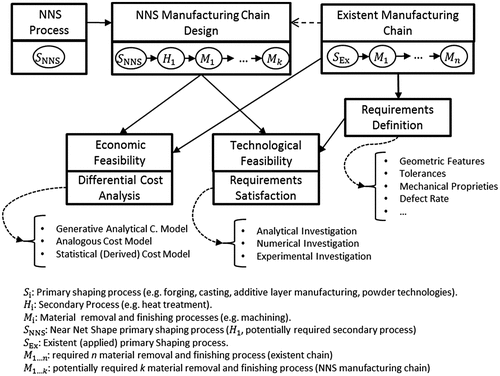
To assess the potential benefit of a new NNS manufacturing process replacing an existing process, the feasibility needs to be systematically assessed. Because the authors’ proposed methodology considers both technological and economic feasibility (shown schematically in Figure ), it is referred to a ‘Differential Cost and Feasibility Analysis’ (DCFA). The first step assesses the ability of the new process chain to produce a component that satisfies the specifications (i.e. geometric features, tolerances, mechanical properties, defect rates). In contrast, the economic feasibility describes the efficiency of the new manufacturing chain and by measuring the resources used for producing the component (i.e. cost) and comparing them to the current method of production.
In other words, the approach uses the current manufacturing chain as a benchmark for comparison: consequently, both technology (i.e. the product quality) and costs analyses are defined relative to the old manufacturing process.
Although NNS processes can vary in nature (e.g. casting, forging, additive layer manufacturing), they are always a primary shaping process (i.e. one that facilitates the transition from raw material to a semi-finished product). So the choice of NNS operation inevitably impacts the supply chain design (i.e. required machining steps, heat treatments …) and its overall efficiency (i.e. amount of employed resources for reaching the required final production quality). Using the a NNS principles, a reduction of machining (less material waste) and an increasing of raw material usage are the desired results of a new primary shaping process application that maintains at least the current product quality as requirements (i.e. quality improvement and collateral advantages can be achieved, but they are not the main objective).
Technological feasibility (including its post-process operation such as thermal treatments) can initially be done analytically (e.g. upper bound model for hot forging process) or numerically (e.g. viscoplastic model applied to FEM for simulating a flow forming process) and then experimentally validated (i.e. by prototypes and/or experimental testing). Analytical, or numerical, feasibility studies have to be connected to a theoretical model that defines the engineering science of the process; however, other factors, reliability, accuracy and cost, also need to be taken into consideration before simulating the process. Consequently, the final geometry produced by the NNS process and its raw material usage are defined during this phase.
In this work, the economic feasibility is treated as a differential cost analysis. In other words, its main target is to compare the cost differences between the old and new manufacturing process from a holistic view. Such a cost model can be statistical or generative-analytical (Layer, Brinke, & Houten, Citation2002) depending on the nature of the process, the information available, the required level of accuracy and cost variables. Many dedicated cost models (Bariani, Berti, & D’Angelo, Citation1993; Jung, Citation2002; Nagahanumaiah, Mukherjee & Ravi, Citation2005; Park & Simpson, Citation2005) and general cost models (Allen & Swift, Citation1990; Esawi & Ashby, Citation2003; Niazi, Dai, Balabani, & Seneviratne, Citation2006; Weustink, ten Brinke, Streppel, & Kals, Citation2000; Yang & Lin, Citation1997) can be found in the literature (Table ).
3. Case study – near net shape manufacturing of a valve cage by centrifugal casting process
The following sections describe a case study conducted to both detail and validate the application of the framework.
3.1. Valve cages for flow control valves
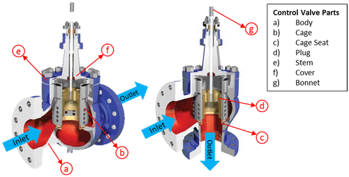
The case study is focused on flow control valves, which are used in many industries such as food and beverage, heating, water, energy, paper and pulp. In each of these applications, flow control valve regulates the flow and/or pressure of a fluid. Control valves normally respond to signals generated by independent devices such as flow meters and temperature gauges. The valve modulates the flow of the controlled fluid passing through a valve body, and would typically include internal components such as closure member, seat ring, cage, stem and stem pin (Figure ). This case study was developed in collaboration with a manufacturer of industrial valves in the UK.
The Valve Cage is a hollow cylindrical trim element that is sometimes used as a guide to align the movement of a valve plug with a seat ring. It may also act to retain the seat ring in the valve body. On some types of valves, the cage may contain different shaped openings (i.e. usually cylindrical or conical holes of different diameters) which act to characterise the flow through the valve. The cage may also act as a noise attenuation or anti-cavitation device. The cage is a part of the valve that surrounds the plug and is located inside the body of the valve. Typically, the cage is one of the greatest determiners of flow within the valve. As the plug is moved, more of the openings in the cage are exposed and flow is increased and vice versa. The design and layout of the openings can have a large effect on the movement of liquid through the valve (i.e. the flow characteristics of different materials over a range of temperatures and pressures). Cages are also used to guide the plug to the seat of the valve to ensure a good shutoff, which removes the need for the movement to be guided from the valve’s bonnet. The walls of the cage contain openings that usually determine the flow characteristic of the control valve (i.e. quick opening, linear and equal percentage)
The valve cage used in this study varied in diameter from 80 to 700 mm (approximately), corresponding to the nominal size range of the valve, which varies between 40 and 60 0 mm (1.5”–24”) (i.e. reference for the cages dimensions). Similarly, the cage materials varied across a range of steel: 420 Stainless Steel, 316 Stainless Steel, 17–4PH Stainless Steel, Monel K500, Hastelloy, Duplex and Inconel. Some of the cages include tungsten carbide or stellite coatings (in areas in direct contact with the seat). The high percentage of material costs in the final component together with extensive machining required for the bigger sizes made this component ideal for a NNS study.
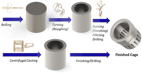
Currently, the valve cages production volume of the case study manufacturer is around 310 components per year (based on 2014/2015 production). In the past, the component was turned from a solid stock bar (cylinder). The requested blank dimensions need to take into consideration the machining allowances. The turning process is performed in a sequence of steps: internal roughing, internal finishing, external roughing, external finishing, filleting and chamfering and holes drilling. Figure illustrates the manufacturing chain and the shape of the parts (i.e. detailed engineering drawings could not be shown for reasons of commercial confidentiality).
3.2. Centrifugal casting process
In centrifugal casting (Figure ), a permanent mould is rotated continuously about a fixed axis at high speeds (300–3000 rpm) as molten metal is poured. The molten metal is centrifugally ‘thrown’ towards the inside mould wall, where it solidifies after cooling. The resulting casting is usually fine-grained with size of the grains decreasing towards to the outer diameter. Impurities and inclusions are squeezed by the more dense (i.e. purer) material to the surface of the inner diameter, which can be machined away. The combination of grain structure and purity results in material properties that are superior to conventional casting and close to hot forging.
Figure 4. True centrifugal casting and semi-centrifugal casting (Swift & Booker, Citation2013).
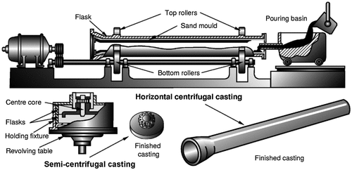
The process can use a rotating semi-permanent, or expandable, mould to both guide the melted material movement under centrifugal force, and catalyse the solidification while enhancing quality. Most metals suitable for static casting are also suitable for centrifugal casting (i.e. all steels, iron, copper, aluminium and nickel alloys). The process’s most common variants are referred to as: true centrifugal casting, semi-centrifugal casting and centrifuge casting (Kalpakjian & Schimd, Citation2009).
In true centrifugal casting, the molten metal is poured into a high-speed rotating mould (300–3000 rpm depending on diameter) until solidification takes place. The axis of rotation is usually horizontal, but may be vertical for short work pieces (Swift & Booker, Citation2013). Good-quality castings (i.e. low defect rate and impurities), high-dimensional accuracy (i.e. in comparison with other casting processes) and good external surface detail are produced by this process. Material properties of the castings vary with distance from the axis of rotation. Mechanical properties and grains structure are comparable with forged product ones. Because centrifugal force is largest at the periphery, the inner material is less dense (in the molten state) and so collects all impurities (that typically have lower density than the metal). This material is usually machined away. Centrifugal casting has the lowest porosity among the casting processes (Schey, Citation1999). True centrifugal casting is used for cylindrical components with high duty applications.
In the literature, experimental articles (Chirita, Soares, & Silva, Citation2008; Huang, Liu, Lv, Liu, & Li, Citation2011; Jain, Rathore, & Gorana, Citation2016; Karun et al., Citation2015; Lee & Hyun, Citation2012; Liu et al., Citation2005; Luan, Song, Bai, Kang, & Li, Citation2010; Sui et al., Citation2016; Watanabe, Miyakawa, Takada, Okuno, & Okabe, Citation2003) focus mainly on the impact of process parameters and interaction between materials (i.e. moulds and workpiece) on the final product’s microstructure and mechanical properties. Numerical articles (Chang, Kim, & Hong, Citation2001; Fu et al., Citation2008; Keerthiprasad, Murali, Mukunda, & Majumdar, Citation2011; Long & Zebin, Citation2016; Ping et al., Citation2006; Song et al., Citation2012; Zagorski & Sleziona, Citation2007) focus on predicting the microstructure’s mechanics (in macroscale and microscale), fluid dynamic behaviour (turbulences and fluid states), temperature and velocity fields and mould filling conditions for different process parameters and mould geometries.
3.3. Application of centrifugal casting to valve cage production
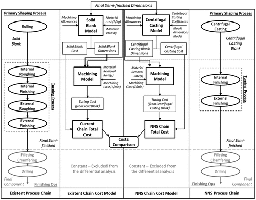
In Figure , the current process chain and the NNS process chain are illustrated. The current process includes cold rolling (solid blank), internal and external roughing, internal and external finish turning, filleting/chamfering and drilling; on the other hand, the NNS process line consists of centrifugal casting (centrifugal casting blank), internal and external roughing, internal and external finishing, filleting/chamfering and drilling. All the machining operations are executed on a CNC lathe at the valve manufacturer.
The total number of machining operations is reduced because of the reduction in roughing operations. This geometry allows roughing operations to be avoided because casting blank is directly finish machined (i.e. internally and externally), as it has been proof machined after centrifugal casting (i.e. this operation will be taken into account in the centrifugal casting cost model). The finish machining operations act on very similar surfaces (i.e. the difference is only the machining allowances used in centrifugal casting); meanwhile, the chamfering/filleting and drilling operations result are unchanged from the current to the NNS manufacturing chain (i.e. as they work on the same geometry and material).
As pointed out in the literature review, the current numerical and analytical methods have been built for evaluating different characteristics and more complex materials and applications. In this study, a 450-mm valve cage diameter (i.e. 420 STST) was produced in addition to the analytical cost analysis to validate the results. Its assessment against the specifications and its performance testing is discussed in the following sub-section.
Figure schematises the differential analysis, which determines the economic feasibility of the NNS process. The analytical cost model has been derived from supplier information (i.e. centrifugal casting and solid blank) and machining cost estimation by material removal rate approximation. The complete formulas are showed in Appendix A and described in this section. The cost models' nomenclature is showed in Table A1. Information on moulding and centrifugal casting costs has made it possible for the authors to report the first centrifugal casting cost model (Appendix B).
Figure 5. Schematic of the two process chains and the associated differential cost analysis (i.e. cost models comparison).
3.3.1. Technological feasibility
Commercial confidentiality prevents the reporting of the key features and specified tolerances.
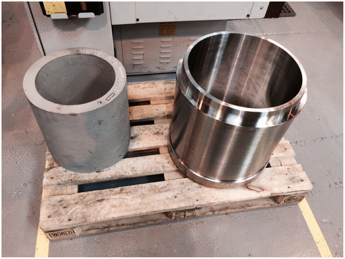
Experimental trials have been conducted in order to determine the technological feasibility of the component. An initial 400-mm cage, made in 420 STST, has been manufactured by the centrifugal casting process supplier and subsequently machined to the final shape (Figure ). This experimental practice helped define the centrifugal casting allowances for inner and outer diameter (as in Equation (Equation9(9) )). Although the best centrifugal casting material proprieties (highest density, hardness, tensile strength) are on the external diameter (i.e. density is highest on the periphery due to the centrifugal force exerted during centrifugal casting operation), 20 mm is used as a default machining allowance on both the inner and outer faces of the cylinder. These allowances are required to allow finish machining of the blank to the final tolerances.
The resultant prototype satisfies the geometrical tolerances and the required mechanical properties. The cage has been assembled in 400 mm nominal diameter valve and has been tested at a high static pressure test (i.e. standard test for every final control valve manufacture at the case study company). The valve, including the centrifugal casting component, passed the test successfully.
The centrifugal casting parts’ defect rate (non-conformances) has been identified as a requirement. The centrifugal casting supplier rate of 1.19% (AMPO, Citation2016) of non-conformity has been considered as satisfactory.
3.3.2. Economic feasibility – differential cost analysis
As described in Figure , the differential analysis model is based on the evaluation of both the current and NNS processes being considered. The cost models aim to give an estimation of the cost difference between the processes chains, estimating the blanks production and machining costs (Appendix A). For the purpose of the case study, the material considered is 420 STST throughout both of the manufacturing processes. As described above, the final machining operations (filleting and chamfering) and drilling operations can be excluded from the differential analysis.
The cost of machining from a solid blank (i.e. current manufacturing chain) can be written as the sum of the solid blank cost, machining cost (i.e. roughing and finish turning) and indirect costs (1); meanwhile, NNS chain’s total cost is the sum of centrifugal casting blank cost (casting operation and proof machining), machining cost (finish turning) and indirect costs (2). As stated above, the machining is operated in the same facility and both the solid blank and the centrifugal casting blank are acquired from suppliers; therefore, the indirect costs can be considered constant and so excluded from the differential analysis. Therefore, Equations (Equation3(3) ) and (Equation4
(4) ) represent the new costs of the current and NNS manufacturing, respectively.
3.3.3. Machining cost model
As the direct machining cost per hour is the same, the turning cost can be written as the sum of the operative and the idle turning time (5). The solid blank cost can be deducted from the billet volume, material density and material cost (given by the solid blank supplier). When large diameters are required for the solid blank, the steel supplier cannot exactly match the specified dimension, so an estimation of the final diameter is given in (8). The required solid blank outer diameter and length also need to take the machining allowances (7, 8) into account.
The centrifugal casting blank cost is defined by the Centrifugal Casting cost model (16–28), which is presented in detail in the next sub-section and Appendix B. As discussed previously, the centrifugal casting blank needed machining allowances even although previously proof machined. Therefore, the final centrifugal casting blank dimension required is as in Equation (Equation9(9) ). The length does not require machining allowances, as it is already cut to shape and proof machined.
As the material is the same for both the processes and the dimensions are similar to each other, the machining parameters can be considered as constants. Therefore, an estimation of the machining time can be obtained using a material removal rate. Removal rate Expression (Equation11(11) ) can be used for calculating the solid blank turning time (12) and centrifugal casting blank turning time (13). The expression of the centrifugal casting blank volume (14), solid blank volume (7) and final (pre-finish operations) volume (15) can be used for calculating the required machining time.
3.3.4. Centrifugal casting cost model
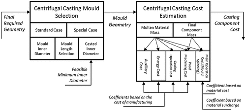
In Figure , the developed cost model for centrifugal casting is schematised. The model’s inputs are the final dimensions which are required for casting blank (including machining allowances, as in Equation (Equation10(10) )). The model is defined by two phases: (1) mould section, whose definition is important for defining the cost and the process mechanics, and (2) the centrifugal casting cost estimation. The complete model formulation is presented in Appendix B.
Phase 1: Mould selection: The first step is to select a standard or custom mould, depending on the final dimensions of the component (16). The two cases can be distinguished by the size of the outer diameter and ratio between the outer and inner diameter (i.e. high component thickness). Component size and its thickness influence the pouring of the melting metal and the rate of its solidification during mould spinning. If the outer diameter (bigger than 800 mm) or the ratio (bigger than 3) is too high, the mould needs to be shorter than a standard case (usually more than 2000 mm) for allowing the molten material to spin and solidify properly. Special moulds are more expensive because they produce fewer components in comparison with a longer mould (i.e. stacked production). For this reason, the formula (Equation16(16) ) distinguishes between ‘Standard’ and ‘Special’ Cases, utilising this distinction throughout the mould selection phase.
The second step is to select the mould dimensions. They can be estimated from the external diameter of the final part. Relationships (17–19) have been derived through general linear models from a centrifugal casting supplier.
The first step is the selection of the mould’s outer diameter. This selection depends on supplier availability and so on the customer demand. In Appendix B, a step graph (Figure ) has been developed from the supplier’s mould dimensions (including both the standard and special cases). Selecting the required outer diameter (x-axis) as input, the step graph defines the mould’s outer diameter (y-axis)
The mould length is determined by Equation (Equation17(17) ), whose input is the previously obtained outer diameter of the mould and which again distinguishes between standard and special cases. Both expressions define a general linear relationship based on the supplier’s data. The input to the equation is the previously obtained mould outer diameter. The error in the linear relationship of Equation (Equation17
(17) ) is 6.68 and 8.12% for the standard and special cases, respectively.
The inner diameter of a component after centrifugal casting is dependent on the volume of molten material poured into the spinning mould. As stated above, the mould’s internal diameter is selected by considering the minimum internal diameter allowed. Again, the internal diameter Formulas (Equation18(18) , Equation19
(19) ) were defined as general linear models derived from the supplier data. Using the mould’s outer diameter and length (previously selected) as input, the calculation of the minimum diameter is able to verify if the required inner diameter is feasible to cast. In the standard case (18), if the required inner diameter is bigger than the minimum calculated inner diameter, it can be selected as the mould’s inner diameter (i.e. casted inner diameter). The formula includes an allowance of 10 mm on the inner diameter. This needs to be taken into account because of the debris and smaller particles concentrated on the internal part of the component. If the requested diameter is smaller than the standard minimum inner diameter, the special case formula is considered. If the required diameter is even less than the special case minimum inner diameter, the mould will be completely filled with metal (so the internal diameter is effectively 0) and the component will need to be machined to the size. In the special case (19), only the special minimum inner diameter is compared with the required one. The minimum inner diameter equation has an absolute average error of 8.56% for the standard and 2% error for the special case.
Phase 2: Centrifugal Casting Cost Estimation: The output of the previous allows both the mass of cast (20) and final component (21) (i.e. after proof machining) to be estimated.
The total centrifugal casting operation cost (i.e. which will be used as centrifugal casting’s blank cost) is estimated by Equation (Equation22(22) ). The identified cost components are as follows: melting cost (23) (i.e. including both the melting cost of the raw material and the re-melting of the proof machining chips); auxiliary cost (24) (i.e. excluding the moulding cost); energy Cost (25); casting operation cost (26) (i.e. gross cost of the operation, including labour, set-up, depreciation and moulding); and proof machining cost (27). All the costs are related to the casting and final masses through coefficients. The used material melting cost coefficient is usually equivalent to the alloy surcharge; meanwhile, the melting chips coefficient is a measure of the saving produced by material saving.
Usually excess lengths of cast components can be amortised by other centrifugal casting productions (i.e. other customers’ request) or re-melted, so the final length and requested length can be considered coincident (Lm = Lf).
4. Discussion: differential analysis results and applications
Differential cost analysis results allow the feasibility of a range of component sizes to be assessed. Although commercial confidentiality does not allow the final cage dimension to be stated, they can be compared though the nominal valve size. The considered model input values are:
| • | Cost of machining per hour per hour: 86 £/h | ||||
| • | Centrifugal casting coefficients (used by the centrifugal casting for 420 STST): material melting cost coefficient (cMaM): 1.8 £/kg; machining chips re-melting cost coefficient (cChM): 1.17 £/kg; auxiliary cost coefficient (cAux): 0.31 £/kg; energy cost coefficient (cEn): 0.62 £/kg; centrifugal casting operation cost coefficient (cCCO): 2 £/kg; proof machining cost coefficient (cPrM): 2 £/kg. | ||||
| • | Material data (solid blank, 420 STST): density, 7200 kg/m3; cost 2.3 £/kg. | ||||
| • | A detailed justification for these estimates and also the effective operative and idle machining times cannot be given because of commercial confidentiality. | ||||
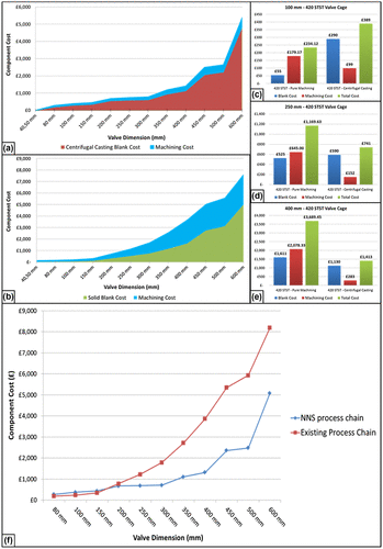
Figure displays the different costs predicted for different valve sizes. Figure (a) and (b) compares the prediction for blank costs (i.e. centrifugal casting blank and solid blank) and machining cost for the NNS chain and the existing chain, respectively. The resultant machining cost (i.e. wasted material) is less in the NNS chain for every size considered, even though the blank costs are higher for the smaller size variants (they reduce as the dimensions increase). Figure (c–e) shows the cost breakdowns for different valve sizes (100, 250, 400 mm, respectively): it is interesting to note how the centrifugal casting cost is bigger than the solid blank cost but decreases as the size increases. On the other hand, the machining cost on NNS chain (i.e. using centrifugal casting) is always smaller than the existing manufacturing chain (i.e. using a solid blank), and the magnitude of this difference grows with the component size. Figure (f) shows the break point between the two different process chains for a range of cage sizes suggesting that the NNS chain will be economic for all the cages having outer dimensions over 200 mm.
Figure 8. Cost comparison of the NNS process chain (a) and existing chain (b). Cost details for different cages sizes: 100 mm (c), 250 mm (d) and 400 (e). Component cost comparison of component evaluated costs for the NNS process chain (i.e. centrifugal casting and finish machining) and the existing process chain (i.e. machining from solid blank) (f).
The potential impact of the introduction of NNS methods for larger parts (i.e. assuming current production methods are retained for cage < 8”) on a biennial production of 636 products change the manufacturing process (i.e. from current process to centrifugal casting application) of 113 cages. The total biennial cost of the current process is £305,150 (i.e. machining costs and raw materials), whereas the use of centrifugal casting would result in a reduction of 26.5%, with an estimated biennial saving of 490 machining hours and 18.9 tons of raw material (The Weir Group PLC, Citation2015). It is interesting to note that for more expensive material (e.g. 316 STST, Inconel), the impact of centrifugal casting would be even larger. As collateral advantage, the lead time has been also reduced from months to weeks due to blank production (i.e. production of large solid blank components takes longer than centrifugal casting) and savings in machining time. As result of this study, all the cages for valves over 250 mm are currently produced through centrifugal casting process, using the designed NNS chain.
5. Concluding remarks and future works
The impact of applying an NNS process to the production of the valve cage known as Centrifugal Casting has been evaluated by assessing the difference in machining costs for both established and alternative processes (finish machining and drilling costs have been excluded, as they are necessary for both the approaches). An adaptable cost model has been created for centrifugal casting, and a methodology (DCFA) has been established for assessing a differential analysis between the old and new process chains. The model can be used for assessing the economic feasibly of every general centrifugal casting application in general.
Introduction of centrifugal casting into the production plan for the manufacture of a control valve’s cage reduces waste and machining time by between 19 and 22%, respectively, generating expected saving of around £50,000 per year (The Weir Group PLC, Citation2015).
Further work could optimise the design of the associated valve shape and the machining process parameters using the cost model reported here (i.e. using evolutionary or other optimisation algorithms). Another possible development is the production of similar component in the valve, directly stacked on the cage (e.g. cage seat), or even including components from other products. Thus, a general framework could be constructed in order to detect possible NNS component/process combinations and assess their feasibility.
Disclosure statement
No potential conflict of interest was reported by the authors.
Acknowledgements
A special thanks to Weir Valves & Controls (Elland), particularly to Matthew Charlton and Steven Brayley, and AMPO (the centrifugal casting supplier), particularly to Iban Mateos and Gillyan Evans. The authors want also to thank WARC (Weir Advanced Research Centre), Weir Group PLC and DMEM of the Strathclyde University of Glasgow for the fundamental and continuous support in this research.
References
- Allen, A. J., & Swift, K. G. (1990). Manufacturing process selection and costing. Proceedings of the Institution of Mechanical Engineers, Part B: Journal of Engineering Manufacture, 204(2), 143–148. doi:10.1243/PIME_PROC_1990_204_057_02
- Altan, T., & Miller, R. A. (1990). Design for forming and other near net shape manufacturing processes. CIRP Annals – Manufacturing Technology, 39(2), 609–620. doi:10.1016/S0007-8506(07)62998-9
- AMPO. (2016). Mrs Gillyan Evans, Pers.Comm, March 16.
- Bariani, P. F., Berti, G., & D’Angelo, L. (1993). Tool cost estimating at the early stages of cold forging process design. CIRP Annals – Manufacturing Technology, 42(1), 279–282. doi:10.1016/S0007-8506(07)62443-3
- Bewlay, B. P., Gigliotti, M. F. X., Hardwicke, C. U., Kaibyshev, O. A., Utyashev, F. Z., & Salischev, G. A. (2003). Net-shape manufacturing of aircraft engine disks by roll forming and hot die forging. Journal of Materials Processing Technology, 135(2–3), 324–329. doi:10.1016/S0924-0136(02)00864-6
- Boothroyd, J., & Dewhurst, P. (1983). Design for assembly: A designers handbook. Boothroyd Dewhurst Inc. Wakerfield, Rhode Island. University of Massachusetts, Department of Mechanical Engineering.
- Castro, C. F., António, C. A. C., & Sousa, L. C. (2004). Optimisation of shape and process parameters in metal forging using genetic algorithms. Journal of Materials Processing Technology, 146(3), 356–364. doi:10.1016/j.jmatprotec.2003.11.027
- Chang, S. R., Kim, J. M., & Hong, C. P. (2001). Numerical simulation of microstructure evolution of Al alloys in centrifugal casting. ISIJ International, 41(7), 738–747. doi:10.2355/isijinternational.41.738
- Chirita, G., Soares, D., & Silva, F. S. (2008). Advantages of the centrifugal casting technique for the production of structural components with Al–Si alloys. Materials and Design, 29(1), 20–27. doi:10.1016/j.matdes.2006.12.011
- Cominotti, R., & Gentili, E. (2008). Near net shape technology: An innovative opportunity for the automotive industry. Robotics and Computer-Integrated Manufacturing, 24(6), 722–727. doi:10.1016/j.rcim.2008.03.009
- Esawi, A. M. K., & Ashby, M. F. (2003). Cost estimates to guide pre-selection of processes. Materials & Design, 24(8), 605–616. doi:10.1016/S0261-3069(03)00136-5
- Fu, P. X., Kang, X. H., Ma, Y. C., Liu, K., Li, D. Z., & Li, Y. Y. (2008). Centrifugal casting of TiAl exhaust valves. Intermetallics, 16(2), 130–138. doi:10.1016/j.intermet.2007.08.007
- Huang, X., Liu, C., Lv, X., Liu, G., & Li, F. (2011). Aluminum alloy pistons reinforced with SiC fabricated by centrifugal casting. Journal of Materials Processing Technology, 211(9), 1540–1546. doi:10.1016/j.jmatprotec.2011.04.006
- Jain, R., Rathore, J. K., & Gorana, V. K. (2016). Design and modelling of dual faceplate centrifugal casting equipment for manufacturing of turbine bearing. CAD/CAM, Robotics and Factories of the Future, i, 13–21 doi:10.1007/978-81-322-2740-3
- Jung, J. Y. (2002). Manufacturing cost estimation for machined parts based on manufacturing features. Journal of Intelligent Manufacturing, 13(4), 227–238. doi:10.1023/A:1016092808320
- Kalpakjian, S., & Schimd, S. R. (2009). Manufacturing engineering and technology (6th ed.). Englewood Cliffs, NJ: Prentice Hall. ISBN: 0136081681.
- Karun, A. S., Rajan, T., Pillai, U., Pai, B., Rajeev, V., & Farook, A. (2015). Enhancement in tribological behaviour of functionally graded SiC reinforced aluminium composites by centrifugal casting. Journal of Composite Materials, 50(16), 2255–2269. doi:10.1177/0021998315602946c
- Keerthiprasad, K. S., Murali, M. S., Mukunda, P. G., & Majumdar, S. (2011). Numerical simulation and cold modeling experiments on centrifugal casting. Metallurgical and Materials Transactions B, 42(1), 144–155. doi:10.1007/s11663-010-9402-4
- Kudo, H. (1990). Towards net-shape forming. Journal of Material Processing Technology, 22, 307–342.10.1016/0924-0136(90)90019-Q
- Layer, A., Brinke, E., & Houten, F. (2002). Recent and future trends in cost estimation. International Journal of Computer Integrated Manufacturing, 15(6), 499–510. doi:10.1080/09511920210143372
- Lee, Y. S., & Hyun, S. K. (2012). Centrifugal casting for unpressurized fabrication of lotus-type porous copper. Materials Letters, 78, 92–94. doi:10.1016/j.matlet.2012.02.098
- Liu, K., Ma, Y. C., Gao, M., Rao, G. B., Li, Y. Y., Wei, K., … Loretto, M. H. (2005). Single step centrifugal casting TiAl automotive valves. Intermetallics, 13(9), 925–928. doi:10.1016/j.intermet.2004.12.004
- Long, W., & Zebin, X. (2016). Research on centrifugal casting of combustion engine cylinder. In The 2nd International Conference on Control, Automation and Robotics Research (pp. 268–272).
- Luan, Y., Song, N., Bai, Y., Kang, X., & Li, D. (2010). Effect of solidification rate on the morphology and distribution of eutectic carbides in centrifugal casting high-speed steel rolls. Journal of Materials Processing Technology, 210(3), 536–541. doi:10.1016/j.jmatprotec.2009.10.017
- Marini, D., Cunningham, D., & Corney, J. R. (2017). Near net shape manufacturing of metal: A review of approaches and their evolutions. Proceedings of the Institution of Mechanical Engineers, Part B: Journal of Engineering Manufacture. doi:10.1177/0954405417708220
- Morita, A., Hattori, S., Tani, K., Takemura, A., & Ashida, Y. (1991). Near net shape forging of titanium alloy turbine blade. ISIJ International, 31(8), 827–833. doi:10.2355/isijinternational.31.827
- Mukherjee, Nagahanumaiah N. P., & Ravi, B. (2005). An integrated framework for die and mould cost estimation using design features and tooling parameters. International Journal of Advanced Manufacturing Technology, 26(9–10), 1138–1149. doi:10.1007/s00170-004-2084-9
- Niazi, A., Dai, J. S., Balabani, S., & Seneviratne, L. (2006). Product cost estimation: Technique classification and methodology review. Journal of Manufacturing Science and Engineering, 128(2), 563–575. doi:10.1115/1.2137750
- Onodera, S., & Sawai, K. (1992). Current cold-forging techniques for the manufacture of complex precision near-net-shapes. Journal of Materials Processing Technology, 35, 385–396. doi:10.1016/0924-0136(92)90329-Q
- Park, J., & Simpson, T. W. (2005). Development of a production cost estimation framework to support product family design. International Journal of Production Research, 43, 731–772. doi:10.1080/00207540512331311903
- Ping, W. S., Rong, L. D., Jie, G. J., Yun, L. C., Qing, S. Y., & Zhi, F. H. (2006). Numerical simulation of microstructure evolution of Ti–6Al–4 V alloy in vertical centrifugal casting. Materials Science and Engineering A, 426(1–2), 240–249. doi:10.1016/j.msea.2006.04.014
- Progress in challenging markets – The Weir Group PLC Annual Report and Financial Statements 2015. (2015). Retrieved from https://www.global.weir/assets/files/investors/reports/The%20Weir%20Group%20PLC%20Annual%20Report%20and%20Financial%20Statements%202015.pdf
- Schey, J. A. (1999). Introduction to manufacturing processes. New York, NY: McGraw-Hill.
- Song, N., Luan, Y., Bai, Y., Xu, Z. A., Kang, X., & Li, D. (2012). Numerical simulation of solidification of work roll in centrifugal casting process. Journal of Materials Science and Technology, 28(2), 147–154. doi:10.1016/S1005-0302(12)60035-8
- Sui, Y., Feng, K., Cheng, C., Chen, X., Qi, J., He, Y., … Sun, Z. (2016). Effects of pouring temperature on interfacial reaction between Ti–47.5Al–2.5V–1Cr alloy and mold during centrifugal casting . Journal of Wuhan University of Technology-Materials Science and Edcation, 31(5), 1105–1108. doi:10.1007/s11595-016-1497-2
- Swift, K. G., & Booker, J. D. (2013). Manufacturing process selection handbook. Oxford: Butterworth-Heinemann. doi:10.1016/B978-0-08-099360-7.00005-7
- Watanabe, K., Miyakawa, O., Takada, Y., Okuno, O., & Okabe, T. (2003). Casting behavior of titanium alloys in a centrifugal casting machine. Biomaterials, 24(10), 1737–1743. doi:10.1016/S0142-9612(02)00583-5
- Weustink, I. F., ten Brinke, E., Streppel, A. H., & Kals, H. J. J. (2000). A generic framework for cost estimation and cost control in product design. Journal of Materials Processing Technology, 103(1), 141–148. doi:10.1016/S0924-0136(00)00405-2
- Witulski, T., Heussen, J. M. M., Winkelmann, A., Hirt, G., & Kopp, R. (1994). Near net shape forming of particulate reinforced Al-alloys by isothermal forming compared to semi solid forming. Journal of Material Processing Technology, 45(1–4), 415–420.10.1016/0924-0136(94)90375-1
- Yang, C., & Lin, T. S. (1997). Developing an integrated framework for feature-based early manufacturing cost estimation. International Journal of Advanced Manufacturing Technology, 307–320.
- Zagorski, R., & Sleziona, J. (2007). Pouring mould during centrifugal casting process. International Scientific Journal, 28(7), 441–444.
Appendix A. Differential cost models
(1)
(2)
(3)
(4)
(5)
(6)
(7)
(8)
(9)
(10)
(11)
(12)
(13)
(14)
(15)
Appendix B. Centrifugal casting cost model
| • | Model Input
| ||||
| • | Model Output:
| ||||
Phase 1: Mould Selection(16)
| (1) | Selecting Mould dimensions.
| ||||||||||||||||
Figure 9. Step diagram for selecting the outer diameter of centrifugal casting’s mould given the outer diameter of the final component.
(18)
(19)
Phase 2: Centrifugal casting cost model(20)
(21)
(22)
(23)
(24)
(25)
(26)
(27)
Table A1.
Cost models nomenclature
Table

