
ABSTRACT
This paper develops a pattern that guides manufacturing system designers and engineers in the identification of requirements and solutions throughout the systems engineering lifecycle. The presented design pattern guides decision-making about the requirements and solutions related to the design and operation of manufacturing plants, lines, cells, and workstations. The research presented in this paper builds on a prior version of the Manufacturing System Design Decomposition, Version 9.2 (MSDD 9.2), which established the requirements and solutions for making effective manufacturing system design decisions. By incorporating decision-centric design and model-based systems engineering tools, MSDD 9.2 is expanded to Manufacturing System Design Decomposition, Version 10.0 (MSDD 10.0) which offers innovative design capabilities in being able to capture and relate all applicable manufacturing system design information as a single source of truth. The design pattern seeks to guide the objective evaluation and introduction of new manufacturing systems, technologies, and products for the manufacturing enterprise.
1. Introduction
When the Manufacturing System Design Decomposition (MSDD) was introduced in 2001, the premise was that the process of designing a manufacturing system consisted of making a series of complex decisions (Hayes & Wheelwright, Citation1979). These decisions would decide the fate of the firm’s high-level objectives. The original MSDD presented, “an axiomatic design-based decomposition of a general set of functional requirements and design parameters for a manufacturing system … to aid engineers and managers in the design and operation of manufacturing systems” (Cochran et al., Citation2001). This paper presents the MSDD 10.0 which represents twenty-plus years of refinement and the incorporation of decision-centric design and Model-Based Systems Engineering (MBSE; Mendonza & Fitch, Citation2013; Ramos et al., Citation2012).
The purpose of the MSDD 10.0 is to provide a manufacturing system design pattern to guide design decisions and to lead the evaluation and adoption of new technologies, and paradigms in manufacturing. To facilitate the adoption requires a design pattern that explains the thinking process involved in developing new technologies and manufacturing systems. For example, the Triple Bottom Line expresses a new business paradigm that impacts the design of manufacturing systems (Cochran & Rauch, Citation2020). However, this business approach is not rigorously defined in engineering terms relative to the impact on the manufacturing system design (Cochran et al., Citation2022). Similarly, Industry 4.0 requires engineering rigor to express design decisions (Rauch & Brown, Citation2021). The MSDD 10 provides a pattern to express the design decisions that impact all aspects of the manufacturing lifecycle including sustainability, cost, quality, flexibility, and Return on Investment (ROI).
The MSDD 10.0 integrates the following classes of design knowledge:
Stakeholder Needs and Use Cases
Functional Requirements (FRs) and associated Functional Requirement Measures (FRms) for manufacturing system design and operation
Decisions – fundamental design issues/questions to translate manufacturing system requirements into physical solutions
Logical and physical architectures of systems
Traceability relationships between design decisions and corresponding requirements
2. Stream of research and industry trends leading to MSDD 10.0
MSDD 10.0 has been built from the contributions of multiple streams of research, industrial experience, and industry trends related to engineering () that include:
Figure 1. Streams of research and industry trends leading to MSDD 10.0.
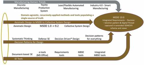
Manufacturing Domain Trends
Axiomatic Design to MSDD to Collective System Design
Decision Patterns for Design
Systems Engineering (SE) Tools
These streams share common principles. The guiding design principle is based on the idea that domain-agnostic, recursively applied methods, and associated tools may be used to populate a single source of truth which captures and relates all applicable information. This source of truth may represent the problem domain, solution space and the design thinking necessary to transform a design problem into a sustainable solution.
2.1. Contributions from model-based systems engineering tool evolution
This research seeks to leverage the power of modern MBSE tools (and the structured languages behind them) to provide a single source of truth concerning a system. The use of MBSE tools enables a designer to evaluate a system from multiple fit-for-purpose viewpoints that enable effective collaboration among all stakeholders across the entire system lifecycle. To capture the rich relationships among the lifecycle design information, this research extended Vitech’s GENESYS MBSE tool suite to create new information classes, relationships, visualizations, and reports to accomplish the integration of the four research and industry trends expressed in (Vitech GENESYS, Citation2021).
2.2. Contributions from lean and smart manufacturing principles and practices
MSDD 9.2, the starting point for this research, represents a proven design pattern for manufacturing system design. In developing the MSDD 10.0, solutions were identified to decompose the MSDD 10.0 into a multi-layer design pattern. This work expanded on the best practice solutions in MSDD 9.2 associated with the manufacturing system design developed by the Toyota Production System (TPS) and others.
The lean, linked cellular, manufacturing system producing to takt time is one example of a best practice solution in MSDD 9.2 (Black, Citation1991). For example, the lower levels of the MSDD design pattern () include decisions that only result in the context of the top-level design decisions and chosen physical solutions. The strength of the MSDD 9.2 is the structure of the design hierarchy to express the logic of decision making as a decision pattern that requires the statement of a Physical Solution (PS) to achieve a parent Functional Requirement (FR). Each stated Physical Solution then sets the context for determining the next lower level of Functional Requirements. The design pattern expressed by the MSDD 9.2 consists of designing solutions based on parent-level FRm’s. Beginning with FR1.1.3 ‘Meet Customer Expected Lead Time’ this branch of MSDD 9.2 shows the alternating FR-PS hierarchical structure of Functional Requirements (FRs) – Physical Solutions (PSs) in design decision making to reduce the five delays associated with manufacturing lead time (Hopp & Spearman, Citation2011).
Figure 2. MSDD 9.2: lot delay branch design pattern.
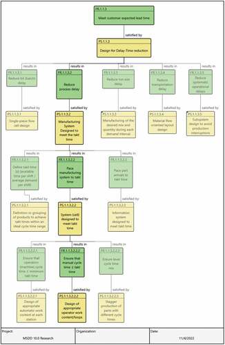
To illustrate the benefit of this hierarchical design pattern, TPS is known for the use of the standing, walking worker in cells who perform a work loop that is balanced to takt time (Black, Citation1991). An example of how the MSDD expresses the hierarchy of decisions that led to the design of appropriate operator work content/loops lowest level solution (PS.1.1.3.2.2.2) is illustrated in . The FRs are depicted as green boxes and PSs as yellow boxes. The context for PS.1.1.3.2.2.2 required a higher-level solution to FR1.1.3.2.2 Pace manufacturing system to takt time. The higher-level design solution is that the system (cell) designed to meet takt time (PS1.1.3.2.2).
PS1.1.3.2 Manufacturing System Designed to meet the takt time is the parent PS that led to FR1.1.3.2.2. Manufacturing System designed to meet the takt time PS1.1.3.2 is the result of the design decision to achieve FR1.1.3.2 Reduce process delay. Moving up the hierarchy, PS1.1.3 Design for Delay-Time reduction is the parent physical solution of FR1.1.3.2 Reduce process delay. PS1.1.3 is designed to achieve FR1.1.3 Meet customer expected lead time which is the highest-level FR that drives the delay reduction branch of the MSDD.
The above description of worked through a bottom-up view of the design to illustrate the thought pattern that led to the lower-level PSs. Working upward from the lower levels of the MSDD 9.2 design pattern reveals the higher-level design relationships that influence the lower levels of decomposition. However, the underlying decision-making process the designer uses is not captured in MSDD 9.2 and therefore can only be assumed. The available PS alternatives and the reasoning for choosing a specific PS is left inside the designer’s head. The benefit of the MSDD 10.0 is that it provides a robust means for documenting design decisions. In addition, the MSDD 10.0 information meta-model defines the relationships among classes of information and enables the designer to communicate the sources of information that the designer considers when choosing a Physical Solution.
The top-down approach, on the other hand, enables the designer to express the alternative physical solutions that are considered before proceeding to the next level of decomposition. MSDD 10.0 includes a new class of information to express the criteria for choosing a PS alternative. This class of information is called the decision class to express why a given PS alternative is chosen.
MSDD 10.0 extends MSDD 9.2 even more by expressing a lifecycle design pattern from enterprise and product concept design to sustainability. MSDD 10.0 has the capability to incorporate requirements for Industry 4.0 (Leng et al., Citation2021).
3. Literature review
As explained in the Introduction section, there are four streams of research and industry trends that led to the development of MSDD 10.0 as depicted in . These trends are presented in more detail in this section of the paper. Collective System Design refinement of MSDD and Axiomatic Design
3.1. Collective System Design refinement of MSDD and Axiomatic Design
This first stream of MSDD 10.0 describes the formulation of the Collective System Design Methodology as a refinement to earlier versions of MSDD and Axiomatic Design (AD) as the MSDD is the result of the application of the AD method and the principles behind the Toyota Production System (TPS) for the design of manufacturing systems. The MSDD has been validated and refined by use with over 70 industry partners who are producing industrial products ranging from aircraft to thermocouples (Cochran et al., Citation2001; D. S. Cochran & Dobbs, Citation2001; Cochran et al., Citation2016).
Axiomatic Design uses a fixed four-level structure to represent requirements flow-down:
Customer Needs (CN)
Functional Requirements (FR)
Design Parameters (DP) also known as Physical Solution (PS)
Process Variables (PV)
It is important to emphasize that the MSDD 10.0 is the result of nearly twenty-five years in development. There have been three main milestone revisions of the MSDD: v5.x (Suh et al., Citation1998), v8.3 and 9.2. Versions 5.x developed the notion of Return on Investment (ROI) at the first level of the decomposition. V8.3 was a major refinement that incorporated customer needs and resulted in the five branch framework of today (Cochran et al., Citation2001):
Quality
Predictable Output (by Identifying and Resolving Problems, and Predictable Resources)
Lead time Reduction by minimizing the 5 Delays
Minimizing Labor Cost by minimizing motion waste
Investment that implements the system design instead of compromising it
Version 9.2 refined the definitions of the FRs, FRm, and introduced the term Physical Solution (PS) as a refinement of V8.3 (Smith et al., Citation2018, Shah, Citation2019). The terminology was updated from Design Parameter (DP) to Physical Solution (PS) to emphasize to users of the MSDD that an FR describes what a manufacturing system must achieve, and that the designer chooses a physical solution to achieve that FR. Terminology was also made more consistent. For example, references to operators, workers, workforce personnel, and labor were replaced with the term, ‘people’ (Shah, Citation2019).
The focus of AD, when used for product design, is to maintain, ‘the independence of the FRm’s through the selection of DPs, e.g. to eliminate coupling (Suh, Citation1990). The AD community is broad; FRs are written in a variety of styles (Thompson, Citation2013). Some FRm’s are stated as quantitative parameters to be improved, e.g. ‘increase time between charging’ and others are stated as pure functions, e.g. ‘recharge battery.’
A Design Matrix is used to capture and visualize the FR-DP relationships expressed either mathematically (as coefficients) or qualitatively with X’s and O’s. In practice, DPs are often expressed in text form as physical solutions, rather than as quantitative metrics (Gebala & Suh, Citation1992; Thompson, Citation2013).
Collective System Design (CSD) incorporates AD but extends to include the following pedagogical refinements and enterprise design principles:
P1. Pedagogical Refinements
Emphasizes that partially coupled designs are best described as Path-Dependent designs – Sets the order of precedence for achieving FRs when coupling cannot be eliminated completely. Use of CSD on manufacturing systems has demonstrated the importance of controlling variability. Path dependency expresses the implementation precedence of physical solutions and captures the ripple effect of process variation across all aspects of the design.
P2. FR-PS Design map/decomposition
– Summary of the product design visualized as a FR-PS-FR … branching hierarchy.
P3. Enterprise Design Principles
P3.1. Flame model of systems – Asserts that the precursor to effective engineering is setting an organizational ‘tone’ built upon leadership-driven team-wide commitment to continuous learning and cycles of improvement (Cochran et al., Citation2016). Cultural change and collective agreement are prerequisites for great engineering.
P3.2 Axiomatic Design as a language to express the design of a system – realization that to express one’s thinking about design (or design thinking) that a language or taxonomy for design is required (Foley & Cochran, Citation2017).
P3.3 Diamond Model of Design – Expresses the Four Principles of Design: P3.3.1 Robustness – achieving FRs in spite of Variation, P3.3.2 Innovation to Achieve System Purpose (FRs), P3.3.2 Design to Eliminate Variation, and P3.3.3 Reduce Flow Time in System, P3.3.4 Controllability – Immediately identifying and responding to Disruptions (abnormal conditions) in a standardized way (Cochran, Citation2010). These four principles are enhanced by the MSDD 10.0ʹs incorporation of these principles as FRs into the design decomposition.
3.2. Evolution in systems thinking
The second stream describes the evolution in systems thinking to letting decisions drive design to the development of patterns of decisions that guide design. Decision-centric Design, the third stream that flows into the MSDD 10.0, is based on the observation that there is a pattern of decisions behind every strategy, architecture, design or even life (Mendonza & Fitch, Citation2012). The method uses a less-traditional definition of a decision. The approach is that a design decision describes a fundamental question or issue that demands an answer or solution instead of using the term ‘decision’ to imply the solution alternative chosen by the designer.
Defined this way, decisions are a means of decomposing the entire problem domain into a set of loosely coupled, well-framed questions that demand answers. The entire problem space may be translated into a decision model known as a Decision Breakdown Structure (Mendonza & Fitch, Citation2012). Decision patterns are the generalization of numerous decision models that have been built across a diverse range of problem situations, e.g., business strategy, system/product design and process improvement. Decision patterns typically include the criteria that have been proven effective for evaluating alternatives in a specific decision.
Another significant innovation in Decision-centric Design is the assertion that decisions create and consume requirements and that a Requirement-to-Decision-to-Requirement (R-D-R) traceability model best represents the derivation model for requirements, instead of the prevailing Requirement-to-Requirement (R-R) trace paradigm (Buede, Citation2000; Fitch, Citation2009; Mendonza & Fitch, Citation2013). The R-D-R trace is summarized in the statement, ‘All requirements are derived requirements’ where ‘derived’ signifies that all requirements are the inherent consequences that flow from the alternative chosen in an ‘upstream’ decision. This approach uses the same logical design pattern employed by the MSDD and axiomatic design in general (Cochran et al., Citation2001; Suh, Citation1990) in which the Design Parameter (DP)/Physical Solution leads to the definition of the next level Functional Requirements (FRs). The work of Sobek and Ward similarly defines this idea as set-based concurrent engineering – where sets of DPs or Decisions (D) establish the boundary for the next level of requirements (Sobek & Ward, Citation1996).
3.3. Systems engineering tools
The third stream discusses the advances in tools that support the development of design patterns. Over the past thirty years, the landscape of engineering tools has made a steady march toward increasing digitization, fine-grained information capture and traceability, and the breadth of the engineering lifecycle information that may be captured in a single source of truth with Model-Based Systems Engineering (MBSE; Shevchenko, Citation2020). These software tool trends have placed a comprehensive Digital Thread (Singh & Willcox, Citation2018) within reach of engineers, though the ‘essence’ of such a model is being sorted out in the marketplace of ideas and software tools.
3.4. Manufacturing domain trends
The fourth stream expresses the trends in the manufacturing domain with respect to manufacturing systems and enterprise design. In parallel with the evolution of these engineering methodologies, the Japanese automobile manufacturing triggered a revolution in the conduct of discrete manufacturing. The Toyota Production System (TPS) championed a linked cellular Just-in-Time (JIT) ‘pull’ system for production control that laid the foundation for the ‘Lean’ manufacturing movement (Black, Citation1991). Increasing automation has reduced labor content in product assembly, while significantly increasing the volume and velocity of information that flows through manufacturing and enterprise systems. These trends have set the stage for Industry 4.0; the next level of manufacturing integration that is enabled by a set of information technologies and architectural principles (Kagermann et al., Citation2011).
Industry 4.0 projects fail to deliver the promised business results, particularly when led with a technology-driven focus (Kane et al., Citation2019). According to Soffer, only 26 percent of Industry 4.0 Internet of Things Manufacturing projects succeed; some of the reasons for this low success rate are due to poor problem definition, missing critical data, prototyping products not technically or financially feasible, and failure to align and sync teams (Soffer, Citation2017). Notice that several of these reasons for failure are related to the design process itself. Industry 4.0 is a technology centric approach as characterized by the Boston Consulting Group by nine technology trends that comprise Industry 4.0: Big data and analytics, Autonomous robots, Simulation, Horizontal and vertical system integration, Industrial Internet of Things, Cybersecurity, Cloud computing, Additive manufacturing, and Augmented reality (Boston Consulting Group, Citation2015). These technology trends do not address the process for the design and engineering of systems.
4. Motivation for research
The purpose of the MSDD 10.0 research is to address the need to develop a more comprehensive design pattern that facilitates the digital design of Industry 4.0 manufacturing systems, while capturing the design relationships for every stage of the SE lifecycle. Specific motivators for the research are described below.
4.1. Resolve ambiguities in earlier MSDD information model
Based on experience in industrial research projects and masters-level SE courses, the research identified significant ambiguities in the MSDD 9.2 design pattern. These ambiguities were believed to be limiting factors in the effective design of smart cyber-physical systems. By incorporating methods innovations and information modelling constructs from other engineering communities, this research leads to significant improvement in engineering effectiveness and efficiency in future engagements and class projects.
Axiomatic Design literature (Suh, Citation1990, Citation2001) and the practices that prevailed as the use of Axiomatic Design spread across many domains were the source of the following ambiguities in MSDD 9.2:
Problem Space ambiguity: AD literature and practice constrained the syntax of a Functional Requirement to be merely a Verb-Noun statement, allowing practitioners to mix both pure system functions and measures of performance (Functional Requirements Measures) under the FR umbrella. The majority of the 70 FR’s in MSDD 9.2 were measures of performance, expressing ‘how well’ a system function had to be performed, but without clearly stating the function that each FRm specifies. Technical papers based on AD exhibit similar lack of distinction between these two very different classes of requirements (Durmusoglu & Satoglu, Citation2011; Kulak et al., Citation2005; Rauch & Vickery, Citation2020). The analysis of students’ work completing course projects, upon learning AD, would create something closer to a 50–50% FR-FRm split in their design project assignments when intending to define FRs.
Solution Space ambiguity: Design Parameters had been loosely used in AD to represent either quantitative measures of performance of the design solution, or the design solution itself. The challenge of specifying the strength of relationships in mathematical terms between DPs and the quantitative FRs contributed to DPs often specifying the Physical Solution chosen to meet the FR, not the parameters that would best characterize how the achievement of a DP contributed to the satisfaction of the FR.
Problem-Solution Space ambiguity: Because the distinction between a problem and its solution depends on a clear definition of the System of Interest (SOI) and associated system boundary, requirements are often written that inappropriately contain or imply embedded solution technology and elements. Stating solution-neutral FRs allows the solution space to remain broad in turn fostering creativity and innovation (Brown, Citation2020).
Like the problem of mechanical tolerance stack-up in physical products, the compounding effect of ambiguity in problem space language (FR-FRm), solution space language (DP-PS), and problem-solution boundary ambiguity compounds the challenge when defining and using the AD terms such as coupling and path dependency in conjunction with traditional SE terms such as functional decomposition, functional modeling, performance/budget, and allocation/flow-down (INCOSE, Citation2015).
4.2. Enable capture of a more complete digital thread
The ‘Digital Thread’ is a relatively new term in SE community and literature (Rauch & Vickery, Citation2020). It is not included in the current release of the INCOSE SE Handbook V4.0 (INCOSE, Citation2015). However, the INCOSE SE Vision 2035 document uses digital thread eleven times but without an explicit definition (INCOSE, Citation2021).
Nearly all system modelling languages (including SysML 1.6 and newly proposed SysML 2.0) and supporting MBSE tools lack an explicit Decision Class or supporting classes for decision-informing information such as criteria, alternatives, and performance estimates (alternative vs criteria screening and scoring data; Object Management Group, Citation2019). Furthermore, discussions of the Digital Thread place primary emphasis on the traditional data that define the problem (needs, requirements, use cases) and describe the solution (physical and logical architecture elements), not the THINKING (decisions) that transforms the defined problem into a designed solution.
Approved decisions are the origination point for next-level physical architecture elements, requirement allocation relationships, risks/opportunities, and derived requirements. This research argues that decisions are the primary integrative mechanism for the entire engineering process. In addition, a Digital Thread, expressed as a language and implemented in software tools, requires explicit traceability to and from ‘the decision(s) in the middle between the FR and PS’ to capture sufficient knowledge to be called a Digital Thread.
5. Research process
The research process consisted of four phases: Phase 1 – Preserve MSDD research, Phase 2 – Add value from new sources, Phase 3 – Extend MSDD to address Industry 4.0, and Phase 4 – Continue learning. Using the GENESYS software, graphical views were generated, and the GENESYS Excel Connector was used to identify gaps, overlaps, inconsistencies, and misalignments (GENESYS Excel Connector, Citation2022). The Enhanced Functional Flow Block Diagram (EFFBD) was used to confirm that any set of sibling functions (FRs) completely addressed the intent of a parent FR and was consistent across all siblings based on both control flow and item flow representations (INCOSE, Citation2015). Control flow diagrams were used to represent the sequencing of system functions, and item-flow diagrams were used to represent the interchange of energy, matter, and information between functions.
The views expressed with the GENESYS software enable the traceability of the design decisions. The traceability and communication of the design decisions provides the foundation to express the design logic that characterizes the digital thread with Industry 4.0. New views of the digital thread were prototyped for each phase of the systems engineering lifecycle to improve visualization of derivation traceability threads from requirements to decisions to solutions and then to derived requirements (to start the next level of design). The paragraphs that follow describe each research phase in detail.
5.1. Phase 1 – preserve MSDD research
Methods issues uncovered in the SE courses and industrial engagement projects were incorporated into a proposed PFW Systems Engineering information model (schema) that was captured in Vitech’s GENESYS MBSE software (Vitech, Citation2021). The MSDD 9.2 was imported into GENESYS, mapped to the new information model, and migrated to the new schema. The MSDD 9.2 Design Decomposition (FR-PS hierarchy) was reproduced using the Hierarchy Diagram and verified as complete against the original.
5.2. Phase 2 – add value from new sources
The MSDD was refined and extended to improve its coverage, precision, and usability. To improve coverage, FR-FRm pairs were extracted from multiple other sources and blended into the MSDD model. To improve precision, the MSDD 9.2 FRs were mapped to either pure functions or measures of performance, now known as FRm’s. To improve usability, manufacturing system design decision patterns were developed by identifying the decision that designs a solution for each FR.
5.3. Phase 3 – extend MSDD to address Industry 4.0
Research collaboration was initiated with the Free University of Bozen-Bolzano in Italy to take advantage of their Industry 4.0 knowledge and an initial set of Industry 4.0 needs and requirements that had been developed for Small-Medium Enterprise (Rauch & Vickery, Citation2020). New viewpoints were created to visualize Requirements, Decisions, and Solutions as knowledge layers and inter-layer traceability threads.
5.4. Phase 4 – continue learning
MSDD 10.0 expansion (in terms of the scope of a manufacturing enterprise being addressed) and refinement continues based on lessons learned from the synthesis effort to date, teaching experience during 2022, and industry engagements.
6. MSDD 10.0 structure
MSDD 10.0 refines the definition of FR and FRm. MSDD 10.0 designates the function that a system needs to perform, the FR, versus how well the FR must be performed, called the FRm. The FRm specifies the direction of goodness (e.g., to maximize or to minimize) and an acceptable threshold value that must be achieved by the physical solution chosen by the designer to satisfy the FR. In the case of a bilateral tolerance, the FRm may be stated as maximize being within the upper and lower threshold values.
Instead of changing the original FR definitions in MSDD 9.2, a new class of information was added to specify the function that must be performed independent of how the function is measured (FRm). The reason for taking this approach resulted from the authors’ analysis of MSDD 9.2 against the FR/FRm distinction. It was determined that MSDD 9.2 was primarily populated with FRm’s but were stated as FRs. For this case, the FRs were re-classified as FRm’s. FRs designating the function that a system needs to perform were then aligned with the FRm’s and were validated by constructing a functional model depicting the FRs, control flow, and item flow.
The validation approach is that an FRm must only and always exist in the context of the FR it specifies. An FRm is defined as a performance improvement vector associated with an FR. Choosing a physical solution (based upon a defined decision class of information) results in the next level of functional decomposition which includes FR control item flow and FRm mathematical flow-down.
To address the above ambiguities, this research has expanded the MSDD to include:
Updated information model/GENESYS software schema reflecting new classes of information that includes the Decision Class and PS Alternative Class
140 Functional Requirements (FRs)
146 Functional Requirement Measures (FRm’s)
176 Items that flow between FRs
23 Use Cases
104 Decisions with 52 Criteria and 52 Solution Alternatives
Approximately 550 other source objects that capture imported documents from which FRs, decisions, solutions, etc. were ‘mined’
Approximately 2000 relationships that create the digital thread associated with the MSDD 10.0 design decision pattern
New views extracted from MSDD 10.0 to further collaboration, review, and refinements to manufacturing system design research
7. Description of views and relationships among information classes
provides a top-level view of the PFW SE information model on which the MSDD 10.0 design pattern is based. At the highest level, the design pattern consists of three layers or classes of information:
Figure 3. Information model used to develop the MSDD 10.0 design pattern.
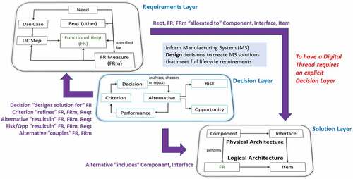
Requirements Layer: Stakeholder needs, use cases, use case steps and various types of formal requirements, including FR, FRm, and other (everything else).
Decision Layer: The fundamental questions that demand an answer and the data that inform each decision. Decisions are how the requirements are transformed into solutions.
Solution Layer: Logical architecture (FRs and the items that flow between them) and physical architecture (components and interfaces).
As illustrated in , FRs appear in both the Requirements Layer as building blocks of the logical architecture and are repeated in the Solutions Layer because the Solution sets the solution space or boundary for the next layer of requirements. shows, but does not elaborate on, numerous important intra-layer relationships between classes of information. For example:
FR → specified by → FRm
Decision → analyzes, chooses or rejects → Alternative
Component → performs → FR
The decision-related relationships reflect the data required to perform decision analysis while using common and mature Multi-Criteria Decision-Making (MCDM) techniques (Sabaei et al., Citation2015). The unique value-creating elements of the proposed information model focus on relationships (wide arrows) between the ‘decision-in-the-middle’ and the requirements (problem definition) and solution design layers. This research proposes these decision-related relationships for consideration as the essential elements in an improved digital thread.
Architectural design (e.g. physical structure) decisions drive the allocation of requirements (of all types, e.g., Requirement, FR, and FRm) to physical architecture elements (see upper right-hand arrow in ).
The relationship of ‘Alternative → includes → Component or Interface’ (depicted as the arrow from the Decision layer to the Solution layer in ) makes an explicit tie between the answer chosen in a decision and the impact that an answer has on the physical structure of the overall solution. Decisions create architecture; therefore, architecture is not the result of drawing models comprised of boxes and arrows that follow a specified format. Architecture results from the process of deciding the best set of physical components, their configuration, and interfaces to create value and to satisfy requirements.
Even more significant than the relationships between the Requirements Layer to Solution Layer and from the Decision Layer to the Solution Layer are the relationships between the decision-layer classes and requirements-layer classes (see upper left-hand arrow in ).
Decision → designs solution for → FR: Every FR that is the responsibility of the System of Interest will trigger the need for a decision that chooses how the FR will be accomplished in the system design. This relationship enables a project team to maintain continuous alignment between the system-level functional model and the project’s Decision Breakdown Structure.
Criterion → refines → FR, FRm, or Requirement (other): Requirements, as written for use in system specification and verification, are seldom stated in a form that enables them to be used directly as evaluation criteria. This relationship highlights the translation of requirements (and associated goals) into evaluation criteria. The lack of this relationship on a requirement/goal indicates that it may not have an appropriate influence on any design decision.
Alternative → results in → FR, FRm, or Requirement (other): This relationship characterizes the assertion that decisions create requirements, e.g., all requirements are derived requirements. This relationship also highlights that the characteristics of a chosen alternative are the source of all derived requirements.
Risk/Opportunity → results in → FR, FRm, or Requirement (other): This relationship is used to capture how choices to mitigate risks or grow opportunities, that are introduced by the chosen alternative, become the source of new requirements across phases of the systems engineering lifecycle.
Alternative/PS Alternative → couples → FR, or FRm: This relationship captures the fact that the solution alternative that is chosen ultimately creates the FR-FR and FRm-FRm coupling that are to be avoided according to Axiomatic Design’s Independence axiom. Coupling (of either type) always flows from design choices.
Together, these five relationships form the MSDD 10.0ʹs refinement of the Requirements-Decision-Requirements (R-D-R) traceability model to a Functional Requirement-Decision-Physical Solution-Functional Requirements (FR-D-PS-FRs) model. This model represents a significant enhancement to the prevailing Requirements-Requirements (R-R) traceability paradigm which does not fully address the requirements derivation process (Fitch, Citation2009).
8. Digital thread viewpoints from MSDD 10.0
The sections that follow illustrate examples of digital thread viewpoints extracted from the MSDD 10.0. These viewpoints were visualized using Vitech GENESYS MBSE software. Brief notes will be provided to explain how these viewpoints may enhance the digital thread associated with manufacturing system design. A structured information model enables the development of multiple viewpoints to improve insight among the stakeholders and the solution designers.
8.1. Requirements pattern for manufacturing system design
Multiple viewpoints have been created to support refinement of the MSDD 10.0 requirements pattern. The Requirements (FR-FRm) Hierarchy in shows the decomposition of the Dispatch Production function (part of daily manufacturing operations) into lower-level FRs. This diagram includes some of the FRm’s to specify how well a function must be performed, but it also indicates where FRm’s are missing.
Figure 4. Requirements (FR-FRm) hierarchy.
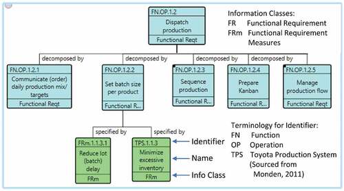
As shown in , the specified by relationship means that the FRm provides a metric for assessing the achievement of an FR. An FR without an FRm should be a point of concern as the ability to know if the FR is achieved is not measurable. This viewpoint provides visual whitespace of missing FRm’s to show potential gaps in the designers thinking.
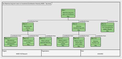
The FRm flow-down in visualizes the contributions of lower-level FRm’s to the achievement of a higher-level FRm, in this case ‘Maximize long term return on investment.’ Even though this is a requirements-focused model, the contribution hierarchy, whether expressed mathematically (as a SysML Parametric Diagram) or qualitatively, reflects the results of multiple system design decisions. Each lower-level design choice may result in a different set of next-level FRs or a different relative contribution of such FRs to a higher-level parameter.
Figure 5. FRm flow-down.
The use of multiple visualizations of requirements information, each with their own data inputs, semantics, and presentation format, creates a knowledge pull from stakeholders and solution developers. Shared knowledge, when visualized formally, can help uncover and resolve gaps, loose ends, and inconsistencies, leading to improved requirements quality. The engagement process to create, review and refine these artifacts may also contribute to stakeholder buy-in to the eventual solution.
In addition, an Enhanced Functional Flow Block Diagram (EFFDB) is another viewpoint that may be used to represent the control flow sequencing logic and item flow (matter, energy, information) interactions between any set of child functions. EFFBD’s or equivalent SysML Activity Diagrams ensure the completeness and consistency of the child functions by specifying functional interdependencies and input/output flows between functions. The item flow viewpoint improves the definition of each function and uncovers any outputs that do not reach another function as an input. The control flow logic viewpoint enables the designer to understand the sequencing of functions to uncover gaps, inconsistencies, and overlaps with respect to how functions interact with each other.
8.2. Decision pattern for manufacturing system design
The decision layer in MSDD 10.0 is composed of multiple layers and branches, beginning from the Enterprise Strategy Decision Breakdown Structure that includes the business decisions that define which products will be produced, which manufacturing processes are used to produce the products, and from which source the product portfolio will be manufactured.
The enterprise decisions concerning manufacturing facilities and allocation of products to facilities (across the supply chain) will define the requirements for each specific plant (). The plant-level manufacturing system design decisions will address the methods by which the plant will operate, e.g., the functional view, and the physical system design comprised of manufacturing cells, production lines, work centers, workstations, and machines for each product family.
Figure 6. Recursive decision pattern for manufacturing system design.
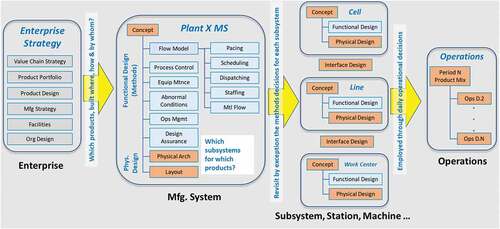
Functional and physical design decisions will be made for each cell, line, or work center, along with interface design decisions when parts/products move between these manufacturing subsystems. Plant-level decisions concerning methods, for example, the Material Flow Concept, may be revisited and tailored at the subsystem level.
The manufacturing system design decisions set up the capability to perform day-to-day manufacturing operations. Operational decisions will be made concerning product mix, sequence, lot size and inventory levels, or as needed, how to respond to a variety of abnormal conditions that disrupt the production flow.
The MSDD 10.0 research has focused on the build-out of the ‘middle’ part of , which currently includes 71 of the 104 decisions captured in the overall design pattern. The remaining 33 decisions relate to the design of either the enterprise or operations.
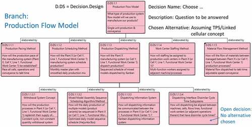
MSDD 10.0 provides different viewpoints about design decisions. The decision pattern viewpoint communicates the hierarchy of decisions that must be made by the designer. The decision pattern of the Production Flow Model branch of the Production Control System is illustrated by each block in . Each block consists of a three-panel format of information that contains the Decision number and name, the description, which is the question to be answered, and the alternative chosen. The decision pattern that is illustrated in assumes a TPS-like linked cellular manufacturing system design (Black & Hunter, Citation2003).
Figure 7. Decision pattern: manufacturing system design.
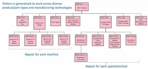
The MSDD 10.0 provides the flexibility to design manufacturing systems at each level of the physical architecture (e.g., cell, line, work center). For example, decisions that are required to complete the design of a manufacturing cell are communicated by the viewpoint in . Note that the operational flow decision for a specific cell could require revisiting any previous production flow decisions. This decision will elaborate what those decisions mean when applied to the production processes and associated workstations/machines that have been assigned to the cell. The cell design pattern includes sub-branches that reflect the decisions to be made for each machine or manufacturing operation/task assigned to the cell.
Figure 8. Decision pattern: cell design.
8.3. Solution pattern for manufacturing system design
The MSDD 10.0 solution pattern may be represented hierarchically as a System Breakdown Structure () or schematically as a Physical Block Diagram (). A System Breakdown Structure is a decomposition of the SOI that includes both engineered and non-engineered ‘components’ that comprise the SOI. Both example diagrams are focused on the Production Control System design branch of the solution pattern. In each case, the nodes in the diagram represent system components, which may be further classified as a subsystem (PCS.0 Production control system), human work (PCS.6 Multi-function worker) or a more general system element (PCS.4.4 Withdrawal kanban).
Figure 9. MSDD solution pattern – system breakdown structure.
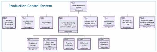
Figure 10. MSDD solution pattern – physical block diagram.
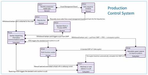
The Physical Block Diagram shows how the physical interfaces between the components will be implemented. These interactions illustrate how the Production Control System components make up a system to achieve the allocated system requirements.
9. Digital thread insights
This section describes three insights gained from this research and a requirements derivation example regarding the digital thread. The digital thread with regard to this work provides a lifecycle view regarding the design, development, operation, and disposal of a manufacturing system, and its constituent processes, elements, and information. The digital thread enables the inter-connection of entities and classes of information that were previously isolated.
9.1. Insight number 1: decision-making process guides definition of solutions
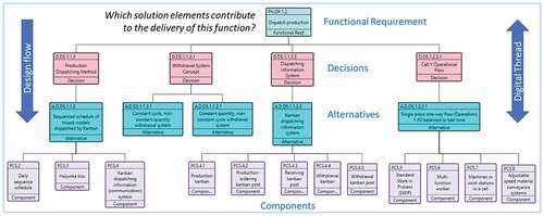
The physical design of a solution does not begin by directly drawing diagrams of the solution, which is the common practice with Axiomatic Design (Suh, Citation1990). The components of the physical design of a solution are conceived as part of a decision-making process to better define and understand the behaviour of solution alternatives (beyond textual descriptions) that will deliver system functionality. represents a digital thread that cuts across all three layers of the MSDD 10.0 pattern to show how a system function (Dispatch Production) is realized as the result of multiple decisions, each of which choose alternatives that include various interacting components. If different alternatives had been selected in any of these decisions, the resulting System Breakdown Structure and Physical Block Diagrams would have been very different.
9.2. Insight number 2: reproducibility of digital thread requires FR-D-PS-FRs design pattern
This work asserts that any digital thread should enable reproduction of the FR-D-PS-FRs trace depicted by . This trace captures the middle layer of decisions through which the physical solution architecture is conceived, evaluated, and selected for implementation. A well-defined digital thread should record not only the allocation of requirements to solution components, but also the thought process used to arrive at those allocations.
Figure 11. Digital thread: requirement – decision – solution architecture.
9.3. Insight number 3: digital thread requires derived requirements based on understanding of the decisions and PS alternative chosen at parent level
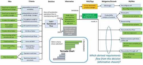
A complete digital thread should also capture and visualize how design decisions create the next layer of derived requirements. shows a populated example of the FR-D-PS-FRs traceability thread for the Cell Operational Flow decision. Although a system may be designed one function or requirement at a time, it is more efficient to address multiple (set-based) requirements (and associated goals) in a single decision (Sobek & Ward, Citation1996). The decision process balances the potentially competing concerns of stakeholders by expressing them as criteria.
Figure 12. Digital thread: requirements derivation example.
9.4. Requirements derivation example
To illustrate that multiple alternatives are conceived as potential solutions to the decision question. Data are gathered to enable alternatives to be screened against requirement (FRm) thresholds (to rule out infeasible solutions) and are scored against goals to identify the overall best fit solution. Risks and opportunities are also assessed in this process and are used as additional criteria to make a final determination between the top few solutions. An evaluation matrix is captured and visualized (in the form of a Tornado Chart, Spider Diagram, etc.) to communicate the decision analysis results that ultimately lead to a commitment to the winning alternative (PS alternative).
This decision analysis effort should lead to a significant increase in the design team’s understanding of the chosen alternative’s Structure, Behaviour, Footprint, Interfaces, and Lifecycle (SBFIL). These inherent design artifacts impose new constraints on every other design decision. Derived requirements become binding on the rest of the system design when a decision is made and approved.
A second path to understanding derived requirements flows from the consideration of how to mitigate the most significant risks and to grow the most significant opportunities that are introduced by a design alternative. Risk mitigation actions (preventive, contingent, and monitoring), if determined to be worth the investment, also create derived requirements. Similar thinking may be applied to growth opportunities.
A second glance at reveals the topology of information that is common to any individual decision. Many requirements/goals, expressed as criteria, constrain the design decision, leading to the selection of one or more alternatives for implementation. Chosen alternatives lead to many derived requirements, whether as inherent consequences or actions to protect against risks or to grow opportunities. The many-to-one-to-many (fan-in/fan-out) topology depicted by the figure illustrates how decisions serve as the integrative mechanism within the design process.
Derived requirements, whether generated from an alternative, its risks or its opportunities are like any other requirements. Derived requirements will drive (through translation into criteria) other design decisions. Viewed across multiple decisions, the result is closer to a digital mesh than a digital thread.
10. Research findings
The MSDD 10.0 research effort has fused knowledge from multiple sources to create innovative and trustworthy patterns for manufacturing system design. The patterns represent an improved capability to accelerate projects that add to business value by making manufacturing systems smarter and the design pattern less ambiguous.
This paper suggests that the use of the MSDD 10.0 as a framework for Industry 4.0 investments in the context of the manufacturing system design will improve business results by:
Understanding and employing the latest technologies that enable achieving the manufacturing system FRs.
Focusing on the manufacturing ‘problem,’defined as a requirements design pattern, as a subset of the larger business enterprise.
Providing well-framed decision/criteria patterns to guide objective evaluation of manufacturing technology, while supporting concurrent engineering of products and the manufacturing systems that build these products.
At this point in the progress of MSDD 10.0 development and validation, the authors assert the findings that follow. First, the ability to capture and relate all applicable design information as a single source of truth. The information model is comprehensive as it can merge and align information pulled from multiple sources that use a variety of SE methodologies. Although the latest information model is larger than MSDD 9.2 (by adding more knowledge classes, relationships, and viewpoints), the observation is that well-structured information dramatically reduces the ambiguity in engineering work products and communication between members of a design team.
It is important to note that an object-oriented information model can manage many different interactions and relationships, there is an increased recognition of the need to apply scalable rigor, e.g., tailor the effort, volume and granularity of data captured to match the estimated contribution of any model or information to project success (Mendonza & Fitch, Citation2012). Structured system models should not be one-size-fits-all.
Second, MSDD 10.0 provides a traceable and reliable method to identify and update requirements during each phase of the systems engineering lifecycle, The AD/CSD and Decision-centric Design methods assume that the design process can be modeled as a recursively applied branching relationship between FRs and PSs. No adverse information has emerged to challenge this assumption. The PFW team was able to represent the design process for a manufacturing system as a FR-D-PS-FRs pattern, even though the model was synthesized from different sources that promote differing engineering methodologies.
Third, enable rapid feedback and update of the results of verification and validation protocols over the lifecycle of SE requirements. Modern MBSE tools were confirmed as essential to scale the use of the MSDD 9.2 to MSDD 10.0 to incorporate the SE lifecycle requirements. The PFW team could not have efficiently executed this research or gained the resulting insights without the ability to visualize complex relationships in many viewpoints pulled from a common source of information with the GENESYS schema. However, a need was discovered for new viewpoints to be developed that require additional network diagram types, beyond simple hierarchies to illustrate coupled design and path dependent relationships, and traditional SE or SysML diagrams.
MSDD 10.0 may provide a promising foundation for guiding Industry 4.0 investments and projects. It is complete enough to add value to manufacturing system design projects today. Such engagements are essential to continuing to improve the design pattern. Finally, requirement, decision and solution patterns are all valuable types of enterprise intellectual property. These patterns are connected according to an intuitive structured model but must be continuously aligned. Changes to the requirement pattern must be reflected in updates to the decision pattern and the solution pattern that flows from each decision.
11. Opportunities for MSDD 10.0 Improvement
Although this research effort has demonstrated the potential value of an integrated requirement-decision-solution pattern for manufacturing system design, it has also identified numerous opportunities for improvement of the MSDD 10.0 pattern and associated methods and tools.
First, the research has identified unresolved ambiguity in the use of the term, coupling. At least two types of coupling were identified that require additional effort to distinguish.
Performance coupling, in which a physical solution creates a mathematical relationship, particularly a competition, between FRm’s. Improvement in one FRm is coupled with reduced performance in another FRm. Architectural coupling that results in excessive item-flow density on a logical or physical N-Squared Diagram. Dense item flow between functions implies that a design change in how one function is delivered will likely have a large ripple effect on other functions.
Second, given that a decision (alternative selection) may lead to a different functional decomposition, how may the current heuristic(s) for deriving next-level requirements from a decision be improved?
Third, the MBSE software tool chain required to implement the PFW concept of a digital thread is complex and not well supported among current tool offerings. How may the information model required for a decision-centric digital thread be realized in software?
Fourth, integrate additional Industry 4.0 requirements, decisions, and solutions into the pattern and resolve gaps, overlaps and inconsistencies between the various sources of Industry 4.0 requirements and information classes.
12. Future research
The PFW team is seeking to extend MSDD 10.0 to improve its value/usability through both academic collaboration and industrial engagement projects. Potential research topics that will increase the value of the MSDD in the context of the systems engineering lifecycle include the following items.
12.1. Methods refinements and extensions
This section describes the planned methods, refinements, and extensions to MSDD 10.0:
Refine the types of coupling represented and how this coupling may be visualized and mitigated.
Refine heuristic(s) for deriving next-level requirements from decision (alternative chosen).
Determine cost/benefit of various models, e.g., EFFBD, in different engineering uses cases.
Develop model validation rules and automation to highlight exceptions/loose ends.
Extend to Product Line Engineering (PLE) – variation points (ISO/IEC 26580, Citation2021).
Extend to innovation via TRIZ (Altshuller, Citation1999).
Extend to incorporate verification and validation.
Conduct Industry 4.0 engagements to extend, validate and refine the model/patterns for completeness, consistency, and usability.
Integrate Industry 4.0 principles: Interconnection, Information Transparency, Technical Assistance, Decentralized Decisions, Service Orientation, Modularity (Ilanković et al., Citation2020).
Define and validate a common functional model for ‘smart’ systems: Create – Communicate – Aggregate – Analyze – Act (Deloitte, Citation2015).
13. Conclusions
This paper has presented the MSDD 10.0 research which provides a comprehensive system engineering lifecycle design pattern for developing sustainable manufacturing systems. The MSDD 10.0 lays a foundation for implementing the principles of Industry 4.0 integrated with the practices established by TPS and Lean.
Three innovative design capabilities were introduced by incorporating Decision-centric design and model-based systems engineering tools into the research for MSDD 10.0. The first capability was introduced by means of an underlying information model that enables the capture and relatability of manufacturing system design information as a single source of truth. The second capability builds on the first capability. The information model enabled additional classes of information to capture requirements during each phase of the systems engineering lifecycle. Finally, the MSDD 10.0 design pattern enables a design team to revisit decisions with confidence as solutions fail to achieve the desired function or when requirements change. Prior decisions can be revisited with confidence because of the MSDD 10.0 design pattern. The ability to revisit decisions with confidence enables capability three which is the ability to provide rapid feedback and update of the results of verification and validation protocols.
By capturing the design relationships for every stage of the systems engineering lifecycle, the MSDD 10.0 design pattern lays the foundation for developing the digital mesh of design decisions.
Disclosure statement
No potential conflict of interest was reported by the author(s).
References
- Altshuller, G. (1999). The Innovation Algorithm: TRIZ, systematic innovation, and technical creativity. Technical Innovation Center.
- Black, J Temple. (1991). Design of the Factory with a Future. McGraw-Hill. 978-0070055506.
- Black, J. T., & Hunter, S. L. (2003). Lean manufacturing systems and cell design. Society of Manufacturing Engineers.
- Boston Consulting Group. 2015. Industry 4.0: the future of productivity and growth in manufacturing industries. https://www.bcg.com/publications/2015/engineered_products_project_business_industry_4_future_productivity_growth_manufacturing_industries
- Brown, C. A. (2020). Axiomatic design for products, processes, and systems. In D. T. Matt, V. Modrák, & H. Zsifkovits (Eds.), Industry 4.0 for SMEs: challenges, opportunities and requirements (pp. 383–401). Springer International Publishing.
- Buede, D. (2000). The engineering design of systems: models and methods (1st) ed.). Wiley-Interscience.
- Cochran, D. S. (2010). Enterprise engineering, creating sustainable systems with Collective System Design – Part II. The Journal of Reliability, Maintainability, Supportability in Systems Engineering, Spring Journal, 16–21.
- Cochran, D. S., Arinez, J., Duda, J. W., & Linck, J. (2001). A decomposition approach for manufacturing system design. SME Journal of Manufacturing Systems, 20(6), 371–389. https://doi.org/10.1016/S0278-6125(01)80058-3
- Cochran, D. S., & Dobbs, D. C. (2001). Evaluating manufacturing system design and performance using the manufacturing system design decomposition approach. SME Journal of Manufacturing Systems, 20(6), 390–404. https://doi.org/10.1016/S0278-6125(01)80059-5
- Cochran, D. S., Hendricks, S., Barnes, J., & Bi, Z. (2016). Extension of manufacturing system design decomposition to implement manufacturing systems that are sustainable. Journal of Manufacturing Science and Engineering, 138(10). https://doi.org/10.1115/1.4034303
- Cochran, D., & Rauch, E. (2020). Sustainable enterprise design 4.0: addressing industry 4.0 technologies from the perspective of sustainability. Procedia Manufacturing, 51, 1237–1244. https://doi.org/10.1016/j.promfg.2020.10.173
- Cochran, D. S., Smith, J., Mark, B. G., & Rauch, E. (2022). Information model to advance explainable AI-Based decision support systems in manufacturing system design. In D. T. Matt, R. Vidoni, E. Rauch, & P. Dallasega (Eds.), Managing and Implementing the Digital Transformation (pp. 49–60). Springer International Publishing.
- Deloitte. (2015). The more things change: Value creation, value capture, and the Internet of Things. Deloitte Review, (17). https://www2.deloitte.com/us/en/insights/deloitte-review/issue-17/value-creation-value-capture-internet-of-things.html
- Durmusoglu, M. B., & Satoglu, S. I. (2011). Axiomatic design of hybrid manufacturing systems in erratic demand conditions. International Journal of Production Research, 49(17), 5231–5261. https://doi.org/10.1080/00207543.2010.510487
- Fitch, J. A. (2009). Exploiting decision-to-requirements traceability. Briefing to NDIA CMMI conference, Denver, CO (US), 9 November (NDIA).
- Foley, J. T., & Cochran, D. S. (2017). Manufacturing system design decomposition: an ontology for data analytics and system design evaluation. 27th CIRP design conference, procedia CIRP, Vol. 60, pp. 175–180.
- Gebala, D. A., & Suh, N. P. (1992). An application of axiomatic design. Research in Engineering Design, 3(3), 149–162. https://doi.org/10.1007/BF01580517
- Hayes, R. H., & Wheelwright, S. C. (1979). Link manufacturing process and product lifecycles. Harvard Business Review. https://hbr.org/1979/01/link-manufacturing-process-and-product-life-cycles
- Hopp, W. J., & Spearman, M. L. (2011). Factory Physics (3rd) ed.). Waveland Pr Inc.
- Ilanković, N., Zelić, A., Miklós, G., & Szabó, L. (2020). Smart factories - the product of industry 4.0. Systems Research and Behavioral Science, 7, 19–30. https://doi.org/10.31570/Prosp_2020_01_2
- INCOSE. (2015). Systems engineering handbook: A guide for system life cycle processes and activities, version 4.0. John Wiley and Sons, Inc.
- INCOSE. 2021. Systems engineering vision 2035 – engineering solutions for a better world. https://www.incose.org/about-systems-engineering/se-vision-2035
- ISO/IEC 26580. 2021. Software and systems engineering - Methods and tools for the feature-based approach to software and systems product line engineering. https://www.iso.org/standard/43139.html
- Kagermann, H., Wahlster, W., & Lukas, W. (2011). Industry 4.0: On the road to the fourth industrial revolution with the Internet of Things. https://www.dfki.de/fileadmin/user_upload/DFKI/Medien/News_Media/Presse/Presse-Highlights/vdinach2011a13-ind4.0-Internet-Dinge.pdf
- Kane, G., Phillips, A., Copulsky, J., & Andrus, G. (2019). “The Technology Fallacy” – How people are the real key to digital transformation. MIT Press.
- Kulak, O., Durmusoglu, M. B., & Tufekci, S. (2005). A complete cellular manufacturing system design methodology based on axiomatic design principles. Computers & Industrial Engineering, 48(4), 765–787. https://doi.org/10.1016/j.cie.2004.12.006
- Leng, J., Wang, D., Shen, W., Li, X., Liu, Q., & Chen, X. (2021). Digital twins-based smart manufacturing system design in Industry 4.0: A review. Journal of Manufacturing Systems, 60, 119–137. https://doi.org/10.1016/j.jmsy.2021.05.011
- Mendonza, P., & Fitch, J. A. (2012). Decision Management (DM) as the engine for scalable, cross-domain systems engineering. Paper presented at 22nd annual international symposium of the international council on systems engineering, Rome, Italy, 9-12 July 22. INCOSE.
- Mendonza, P., & Fitch, J. A. (2013). Integrating system models around decisions. Paper presented at 23rd annual international symposium of the international council on systems engineering, Philadelphia, PA (US), 24-26 June 23. INCOSE.
- Object Management Group., 2019. OMG system modeling language, version 1.6. https://www.omg.org/spec/SysML/
- Ramos, A. L., Ferreira, J. V., & Barceló, J. (2012). Model-based systems engineering: an emerging approach for modern systems. IEEE Transactions on Systems, Man, and Cybernetics, Part C, 42(1), 101–111. https://doi.org/10.1109/TSMCC.2011.2106495
- Rauch, E., & Brown, C. (2021). Teaching axiomatic design for a long-term sustainable introduction of industry 4.0 in SMEs. Procedia CIRP, 96, 169–174. https://doi.org/10.1016/j.procir.2021.01.155
- Rauch, E., & Vickery, A. R. (2020). Systematic analysis of needs and requirements for the design of smart manufacturing systems in SMEs. Journal of Computational Design and Engineering, 7(2), 129–144. https://doi.org/10.1093/jcde/qwaa012
- Sabaei, D., Erkoyuncu, J., & Roy, R. (2015). A review of multi-criteria decision-making methods for enhanced maintenance delivery. Procedia CIRP, 37, 30–35. https://www.sciencedirect.com/science/article/pii/S2212827115009403
- Shah, S. 2019. Using the Collective System Design Approach to Facilitate a Sustainable Manufacturing System. Purdue University Graduate School. Thesis. https://doi.org/10.25394/PGS.7438727.v1
- Shevchenko, N. (2020). An introduction to Model-Based Systems Engineering (MBSE). Carnegie Mellon University: Software Engineering Institute Blog. https://insights.sei.cmu.edu/blog/introduction-model-based-systems-engineering-mbse/
- Singh, V., & Willcox, K. E. (2018). Engineering design with digital thread. AIAA Journal, 56(11), 4515–4528. https://doi.org/10.2514/1.J057255
- Smith, J., Shah, S., & Cochran, D. S. (2018). Prevention, early detection, and reversal of type-2 diabetes using Collective System Design. The 12th International Conference on Axiomatic Design - ICAD 2018, Reykjavik University, Iceland. Vol. 223 (pp. 01018). MATEC.
- Sobek, D. K., & Ward, A. C. (1996). Principles from Toyota’s set-based concurrent engineering process. Proceedings of the 1996 ASME design engineering technical conferences and computers in engineering conference. California, US. pp 1–9.
- Soffer, A. (2017). Industry 4.0 Initiatives are Failing—Here’s Why. Seebo Blog. https://blog.seebo.com/why-industry-4-0-projects-fail/
- Suh, N. P. (1990). The principles of design. Oxford University Press.
- Suh, N. P. (2001). Axiomatic design – advances and applications. Oxford University Press.
- Suh, N. P., Cochran, D. S., & Lima, P. C. (1998). Manufacturing system design. 48th general assembly of CIRP, CIRP annals – manufacturing technology, Vol. 47, pp. 627–639.
- Thompson, M. K. (2013). A classification of procedural errors in the definition of functional requirements in axiomatic design theory,” 7th International Conference on Axiomatic Design (ICAD 2013).
- Vitech GENESYS. GENESYS Software. 2021. https://www.vitechcorp.com/genesys/
- Vitech GENESYS. (2022). GENESYS Excel Connector. https://vitechcorp.com/software-downloads/
