
ABSTRACT
Wire Arc Additive Manufacturing (WAAM) is a metallic additive manufacturing process based on the fusion of metallic wires using an electric arc as a heat source. The challenge associated with WAAM is heat management and understanding bead geometry. All of the process variables, such as travel speed (TS), wire feed speed (WFS), idle time, combine to produce the geometry of the deposited bead that results in the desired component shape. Therefore, determining a method for selecting a good combination of process parameters is critical to obtain a high-quality part. This article presents a study on how to control the WAAM process to produce a thick part of aluminium alloys. An experimental design is determined to study the influence between various process parameters such as WFS, TS, the layer height, or the length of the bead. Different samples are made using a Yaskawa robot, and the classic CMT (Cold Metal Transfer) mode as a manufacturing method. A new manufacturing method is then proposed by adding an important step in the process parameters determination. The results indicate that the length of the bead has a significant impact on the torch speed of the process.
1. Introduction
1.1. WAAM technology and CMT
Wire Arc Additive Manufacturing (WAAM) is a process based on the deposit of wire beads with the use of (Filomeno Martina, Citation2015):
a heating source: the energy of a wire arc;
a material tank in wire form;
a displacement system.
Various technologies can be used for WAAM, for instance, plasma arc (PAW) (Ding et al., Citation2014), arc welding with tungsten inert gas (TIG), gas metal arc welding (GMAW) with fuse wire and inert or active gas (MIG, MAG) (Ding et al., Citation2015) and Cold Metal Transfer (CMT) (Fronius, Citation2014). FRONIUS company developed in particular CMT as an enhanced system of GMAW (Fronius, Citation2014). Compared to the traditional GMAW, this process named cold welding can reduce heat input, which is an interesting point for additive manufacturing as the objective is to assemble beads for building a part; energy is therefore used to melt a part of the bead previously deposited. A too high energy provided to the bead can lead to material collapsing, thus making it impossible to build the part. The process principle consists in the forward and backward movement of the wire. The bead is then deposited in a series of drops. CMT process (Fronius, Citation2014) has three main benefits compared to standard GMAW:
A clean welding due to the quasi-absence of projections during process;
A limited heat input thanks to the short-circuit;
The arc stability as the arc length is set mechanically.
1.2. Objectives and scope
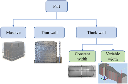
The objectives of this research work are to propose a method to manufacture a part with a thick section and variable width such as shown in (top view) by CMT technology. A classification of the different types of a part is shown in . A distinction is made between a massive part and a wall-type part. A massive part relates to a part with big (compared to bead section dimensions) dimensions in all directions, whereas a wall-type part has got a height and length bigger than its width. A thin wall is defined by a width that equals the width of one bead. Thick walls are larger than a single bead and require a more complex toolpath. It can have a width of a constant or variable value. This paper studies thick walls with a variable width.
Figure 1. Example of a part with a variable section width.
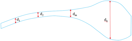
Figure 2. Part typology classification.
Indeed, a state-of-the-art review shows that it is still a challenge today to build parts by depositing weld beads along a varying width while keeping a constant height. This research work therefore focuses on studying both WAAM-CMT manufacturing parameters and filling strategies and strives to maintain a constant height on the whole part. First of all, this article presents the state of the art of filling strategies and models to determine the parameters for thick parts manufacturing with WAAM. The next section explains the manufacturing parameters that have an influence onto this kind of parts. Several experimentations are then described in order to find which parameters need an adjustment. It ends up on the proposition of a new model of manufacturing parameters choices. Finally, a thick part is manufactured using those parameters. In conclusion, major results are presented in terms of manufacturing parameters and filling strategy.
2. State of the art
2.1. Slicing and filling strategy
The generation of deposition trajectories is based on the part CAD model and a slicing step allows to obtain curves representing the manufacturing strategies. It is usually carried out through a series of parallel planes (Panchagnula & Simhambhatla, Citation2016). Depending on the structural features of the parts, different slicing methods have been developed. According to Jing et al. (Citation2018), there are four kinds of slicing methods: basic and adaptive slicing is used with parallel planes for simple parts; multi-direction for overhanging structures; and non-layerwise for free-form parts are for complex parts. The traditional method with parallel planes is used in the present research work as the chosen geometry has got identical sections along z. The parallel slicing make it possible to build flat upper surface for each layer, which is the main purpose of this paper.
Concerning the deposition strategy for a thick part, an analysis of the part geometry allows choosing the right trajectories (Quérard, Citation2019). Two categories of areas arise: zones where wall width is below the width of a bead, which can be made with mono-beads, i.e. without filling; and zones where wall width is greater than the width of a bead, which stands out for needing a filling strategy. The result of these choices impacts the slicing as, for instance, the layer thickness can be different between a mono-bead and a multi-bead component. Three kinds of trajectories can thus be considered: 3-axis, 5-axis, and filling.
In order to manufacture thick parts with WAAM, it is necessary to generate filling strategies by a deposit of beads, side by side within the same layer. In this case, different scanning strategies can be considered: raster (Dunlavey, Citation1983), zigzag (Park & Choi, Citation2000; Rajan et al., Citation2001), contour Farouki et al. (Citation1995); Yang et al. (Citation2002), and spiral (Li et al., Citation1994; Wang et al., Citation2005) (). The raster strategy relies on the projection in one direction (Dunlavey, Citation1983). The zigzag approach combines the parallel lines separated in one continuous scan, which reduces the number of toolpath trajectories (Park & Choi, Citation2000). However, both approaches, raster and zigzag, give poor results because of the discretization applied onto any edge is not parallel to the tool path direction. As an alternative method, the contour strategy can solve this geometrical quality problem by following the geometrical trend of the part contours (Farouki et al., Citation1995). Finally, the spiral trajectory is widely used in numerically controlled machining but does not fit for some specific geometrical models in the AM process (Li et al., Citation1994).
Figure 3. Classical filling strategies.
Depending on the complexity of the part, Ferreira et al. (Citation2022) have proposed different filling strategies for WAAM process. For the profile with a variation of width, three filling strategies were studied: hybrid (contour + zigzag), contour parallel, and pixel. These filling strategies are then compared through experimentation, however as only a single layer is printed, the part height issue cannot be observed.
In conclusion, the existing study highlights that these filling strategies are interesting for different profiles. For the profile with a variable width, the hybrid (contour + zigzag) and pixel filling strategies are good choice for WAAM process. The pixel strategy seems better than the hybrid strategy in a complex case where the width and height of the part are observed. In the present study, the zigzag strategy is chosen. The contour is not taken into account as the part can be machined later. Instead, the focus is set onto the influence of the width variation onto the part height.
2.2. Manufacturing parameters
WAAM configuration is a complex task as many parameters are involved and interdependent. Currently, few studies have proposed a generic method for selecting manufacturing parameters (Quérard, Citation2019). Other studies propose a method selecting manufacturing parameters for a particular part geometry (Cui et al., Citation2021; Zhao et al., Citation2020).
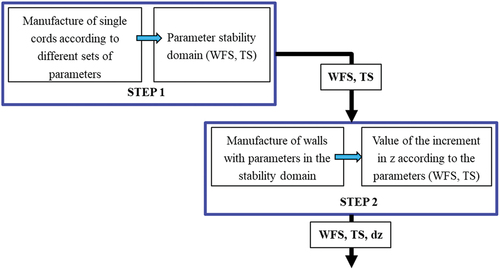
Concerning the manufacturing parameter selection model proposed by Quérard (Citation2019) (), two main steps are included:
Step 1: manufacture of single bead according to different sets of manufacturing parameters. This step makes it possible to obtain a domain of stability of the manufacturing parameters. A set of parameters (WFS, TS) can then be chosen from values in this domain.
Step 2: Simple walls are made with selected parameters to obtain a value of the z-increment (dz) according to parameters (WFS, TS).
Figure 4. A selection parameter model for WAAM by Quérard (Citation2019).
Studies carried out by Cui et al. (Citation2021); and Zhao et al. (Citation2020) consist in selecting the manufacturing parameters based on the heat input at the start of the arc.
Cui et al. (Citation2021) propose a method to manufacture metal block structure parts. The principle of this method is to separate depositing paths and apply different heat inputs to these paths. The filling trajectory is separated into a boundary and inner trajectory. The manufacturing parameters (WFS, TS) are chosen to correspond to the heat input and the bead dimension (height and width). This method is interesting but does not consider walls with a variable width.
Zhao et al. (Citation2020) have proposed a method to generate the adaptive process parameters for the fabrication of large-scale components. The idea is to monitor the temperature of the current layer and predict the next one. Then the manufacturing parameters (WFS and TS) will be modified in function with the predicted temperature to ensure the uniform layer dimension. This prototype was manufactured with a single bead.
Xia et al. (Citation2020) proposed a model to control the layer width during the WAAM process using the vision-based feedback. The WFS is the input, and layer width is the output of this model. A thin wall was manufactured with the single bead using the result of this method.
Many researchers focus their efforts on the influence of the manufacturing parameters onto the welding bead quality (geometry and material health). Dinovitzer et al. (Citation2019) applied Taguchi and ANOVA method for identifying the torch speed, the wire feed, the current, and argon flow rates onto responses. These include the shape, size, and rugosity of beads, as well as the oxidation level, the fusion in depth, and the microstructure. The torch speed and current have the biggest effect on responses. Increasing the torch speed or decreasing the current invokes a reduction of the fusion through the depth and a rugosity increase. Other studies that focused on mono-bead manufacturing (Manokruang et al., Citation2020) have led to the selection of manufacturing parameters and strategies specific to thin parts.
2.3. Conclusion and research question
The above-mentioned current research show the CMT capacity for manufacturing thick parts. This type of process is not easy to control as the parameters are different for each torch system and each material. Welding modes need indeed to adapt the energy input according to the material and wire diameter. Several studies were focused on the thermal behaviour, the control of the heat input, and the model to predict the bead’s dimension. These methods proposed in the existing study were applied to manufacture the large-scale part with a single bead, the block structural with different filling strategies, and the thick wall with a width constant. However, a method for producing a thick wall with variable width has not yet been developed. A synthesis of the manufacturing parameters selection is presented in .
Table 1. Synthesis of existing parameter selection methods.
In this context, the research question is the following:
How to choose process parameters for manufacturing a thick wall with a variation of width in WAAM-CMT in a parallel slicing strategy?
To answer these issues, the main challenge is to master the bead shape (width and height). It is very important to determine an increment in z (between two layers) and lateral offset (between two beads in the same layer). An initial model to choose the process parameters (Wire Feed Speed and Travel Speed) is determined by the author in view of the literature review results. Then various experimentations show which parameters and which filling strategies have to be adjusted to obtain the correct part. They are carried out with geometrical singularities in aluminium Al 5356 and are detailed in the next section. The initial model to choose the process parameters is finally improved after analysing the results of these experiments. A last experimentation is done to validate the final model.
3. Proposition of an initial model to choose the process parameters for manufacturing a thick part
According to the selection parameter model for manufacturing a thin part proposed by Quérard (), an initial model to choose the process parameters for manufacturing a thick part is proposed in this section ().
Figure 5. Initial model to make a choice of the process parameters.
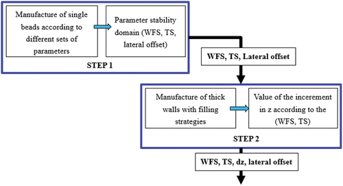
Two main steps are included in this initial model:
Step 1: a single bead is built according to different sets of manufacturing parameters. The width of the bead is measured to determine the lateral offset value. This step makes it possible to obtain a domain of stability of the manufacturing parameters. A set of parameters (WFS, TS) can then be chosen from values in this domain.
Step 2: thick walls are made with selected parameters to obtain a value of the z-increment (dz) according to parameters (WFS, TS, lateral offset).
4. Experimentations
With the aim of observing the issues related to the manufacturing strategy and the choice of manufacturing parameters, a profile with a variation in width such as shown in has been manufactured.
4.1. Manufacturing strategies
Two manufacturing strategies are then defined:
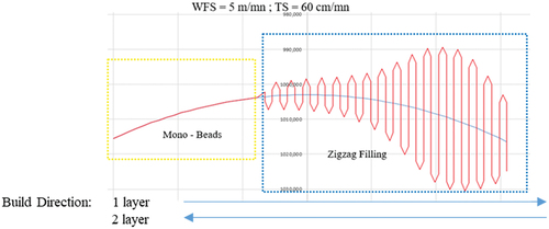
Strategy 1: distinction of two areas in the profile: Zone 1 (boxed in yellow line) is produced in mono-bead because the width is below the width of a bead. Zone 2 (boxed in blue line) is built by using filling zigzags because the width is greater than the width of a bead (Quérard, Citation2019) ().
Figure 6. Strategy with mono-bead and zigzag filling.
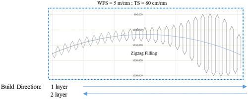
Strategy 2: use of zigzag all along the profile length (). This strategy is defined to compare it with the first one.
Figure 7. Strategy 2 with zigzag filling all along the part.
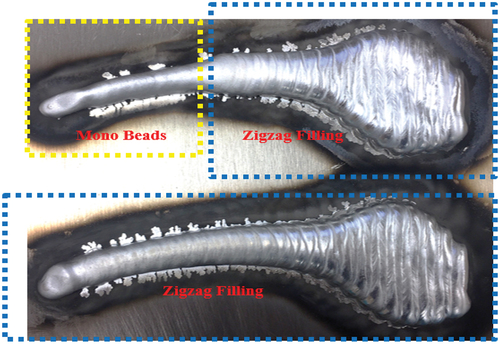
For both strategies, only two layers are built back and forth, in order to better observe the differences of height between both parts (). Concerning the part built with the first strategy, a gap greater than 2 mm is observed between the mono-bead zone and the filling zone. In addition, there is an irregularity in the width when passing from Zone 1 to Zone 2. Concerning the part built with strategy 2, the height is constant on the whole part, as of the second layer. Hence, from a surface and geometrical quality point of view, the second strategy is obviously more relevant than the first one. In order to study the average height of each layer, the same part is then built with more than two layers.
Figure 8. Results of both strategies with two layers.
4.2. Influence of manufacturing parameters onto the average height of the part
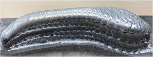
A prototype with eight layers has been manufactured, as shown in . Prototype with eight layers.
Figure 9. Prototype with eight layers.
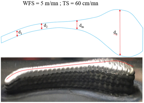
In this experimentation, the difference of height all along the part is outstanding. This height is lower on both sides of the part because of the edges effect. The height of the part is different according to the variation of the bead length (dn). The area where the bead is the longest is the thickest. This problem can be explained as follows: when the zigzag length (d) is greater, the back-and-forth manufacturing time takes longer. The required cooling time is therefore more important, and the temperature of spreading is colder, which entails the manufacturing of more narrow and higher beads.
Usually, the height of the part is rather stable. An average height of 4,6 mm was obtained unlike the theoretical 4.5 mm. In addition, the same issues arose at the edges of the part and within the areas where the bead length changes. For the manufacturing strategy, we recommend using the zigzag filling strategy, regardless of the part width. For the manufacturing parameters, this initial model leads to a height problem. Consequently, a new model needs to be developed in order to select appropriate parameters and is presented in the next section.
5. Development of the initial model of selection process parameters
5.1. Manufacturing parameters choice model
Following the experiments previously done, for a thick part made with the zigzag infill strategy, this model does not seem appropriate because a different average layer height is obtained on our prototype. This problem was presented in section 4.2. A constant value of layer average height is very important to determine the trajectory program.
To solve this problem, the initial model is completed by adding a third step which allows to correct the parameters output from step 2 ().
Figure 10. Proposed model of parameters choice.
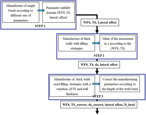
Step 1 and step 2 are presented in Section 3.
Step 3: the thick wall is made with the zigzag filling strategy using the different values of TS depending on wall width. The goal of this step is to determine the function between TS and the wall width. This step is detailed in the next section.
5.2. Correction of the parameters according to the weld bead length
5.2.1. Experimental design
The experimental design aims at determining the relation between travel speed (TS) and bead length (D_bead) to have an average height layer constant. In this study, it is decided to adjust travel speed (TS) because it is easy to change the program as a variable.
A 10-layer thick wall has been chosen as an experimental part () and it was fabricated with the following parameters and strategy:
Welding method: classic CMT
Manufacturing strategy: back and forth trajectory, zigzag filling
Manufacturing parameters: waiting time between layers = 180 s; WFS = 5 m/min
Variables: TS and D_bead
Figure 11. Top view of the part.
Thirty experiments have been performed with three levels of bead length (5, 10, and 15 mm) and 10 levels of torch speed between 4 and 10.5 cm/s. The experimental design is defined in .
Table 2. Experimentation design to determine the function between torch speed and bead length.
5.2.2. Experimental results
The measured average layer height of each trial is shown in . The results of this experiment allow us to determine the average height of a layer (dz_average) as a function of the travel speed (TS) and the bead length.
Table 3. Average height of a layer (mm) based on TS and D_bead.
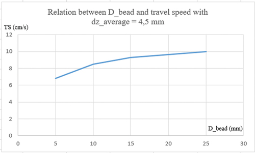
The objective of this experiment is to obtain a function that will allow us to calculate the travel speed (TS) according to the length of the weld bead (D_bead) with a given value of the layer average height. The curves in represent the relation between TS and average height value for differents lengths of the weld bead. For example, for an average height of 4.5 mm, a function between TS and D_bead is obtained (see red curve in ). This curve allows us to determine TS depending on D_bead for a value of dz_average equal to 4.5 mm (). The mathematical description of this function is the following:
Figure 12. Relation between dz_average and travel speed.
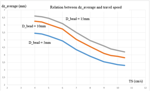
Figure 13. Response surface.
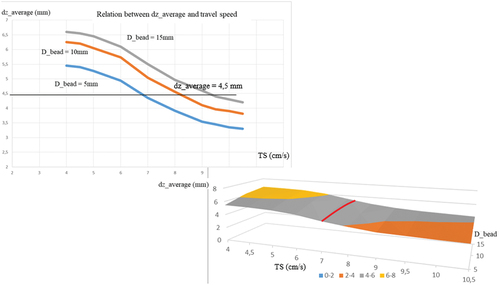
Figure 14. Function between TS and D_bead.
5.3. Experimentation
To verify the improvement resulting from the application of the variation of TS regarding the D_Bead, a new prototype has been fabricated with the correction TS.
The parameters given by the proposed model with a layer average height of 4.5 mm () were used to re-fabricate a part that was manufactured in section 4 ().
The main manufacturing parameters in this experimentation are listed below:
Wire feed speed: WFS = 5 m/min
Travel speed: TS = calculated by the relation function of relation between TS and bead length ()
Waiting time: 180s
Material: aluminum Al 5153
Manufacture strategy: filling zigzag
Deposition of eight layers
The result of this experiment is presented in .
Figure 15. Prototype manufactured with calculated TS.
To evaluate the new strategy, a comparison of the two prototypes (with and without TS calculated) is presented in .
Figure 16. Comparison between two prototypes.
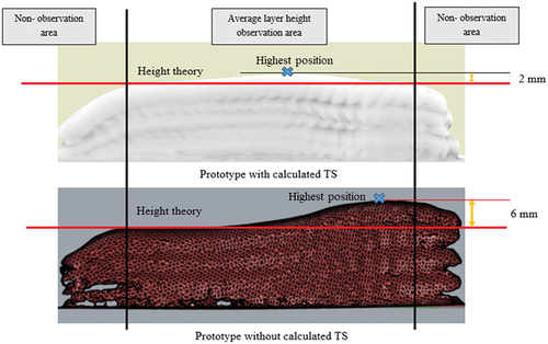
The height of the middle part was measured to observe the average layer height. shows the 3D scan of two prototypes and average layer height observation area.
For prototypes without calculated TS, there is a deviation of about 6 mm compared to the nominal height. This deviation is mainly present in a third of the observation area. For the prototype with corrected TS, the deviation is approximately 2 mm, and it is concentrated on the zone where there is a rapid and large change in bead length.
In this prototype, it can be noticed a difference in height between the middle part and the edge of the part. This issue at the edge of the section has not yet been resolved by just modifying the torch speed. It depends on thermal accumulation. In this experiment, a waiting time is used to cool and solidify the bead. So, the arc has to be started and stopped several times. One solution would be to consider adding a large enough surplus to these edges so they can be removed during the finishing step. Another solution is to reduce the energy and torch speed at the edge of the part and to manufacture the part without waiting time. This problem will be studied in future research.
In a further step, this study will be carried on in order to improve the chosen parameters model. The goal would be to have a constant z level for each layer in order to have an easier toolpath planning.
6. Conclusion and perspectives
This research work focuses on the challenge of in WAAM-CMT a thick section, i.e. with a variable width. Results show that, in order to be able to consider these kinds of parts as of good quality, the part must have a constant height whatever its length and width. Moreover, for a thick part with a geometrical singularity, we strove to identify the best filling strategy as well as the manufacturing parameters that have an influence onto the part quality. As a conclusion:
A zigzag filling strategy brings works fine.
A correctly determined value of the increment in z leads to a good part geometry, i.e. the same as the CAD model one.
To build a good-quality prototype, the travel speed (TS) must vary according to the bead length.
Thanks to the proposition of a new model, this study provides the key elements for manufacturing multi-beads thick parts with WAAM. The third step added to the initial selection model solves the average height problem on the manufacture of thick parts with WAAM. Hence, through a surface response, the new proposed model helps to calculate the travel speed (TS) based on the bead length, with a given value of the layer average height. Finally, the last experimental design shows that, whereas the average height measured in the middle of the prototype section is regular, there is still a need to investigate how the shape part edges can be stabilized. A research work has recently been conducted to understand the bead shape (Manokruang et al., Citation2020) and is currently deepened.
For the next time, a thermal simulation model will be developed to compare with the results of our experimental model.
Disclosure statement
No potential conflict of interest was reported by the author(s).
References
- Cui, J., Yuan, L., Commins, P., He, F., Wang, J., & Pan, Z. (2021). WAAM process for metal block structure parts based on mixed heat input. The International Journal of Advanced Manufacturing Technology, 113(1–2), 503–16. https://doi.org/10.1007/s00170-021-06654-x
- Ding, D., Pan, Z., Cuiuri, D., & Li, H. (2014). Wire-feed additive manufacturing of metal components: Technologies, developments and future interests. International Journal of Advanced Manufacturing Technology, 81, 465–481. https://doi.org/10.1007/s00170-015-7077-3
- Ding, D., Pan, Z., Cuiuri, D., & Li, H. (2015). A multi-bead overlapping model for robotic wire and arc additive manufacturing (WAAM. Robotics and Computer-Integrated Manufacturing, 31, 101–110. https://doi.org/10.1016/j.rcim.2014.08.008
- Dinovitzer, M., Chen, X., Laliberte, J., Huang, X., & Frei, H. (2019). Effect of wire and arc additive manufacturing (WAAM) process parameters on bead geometry and microstructure. Additive Manufacturing, 26, 138–146. https://doi.org/10.1016/j.addma.2018.12.013
- Dunlavey, M. R. (1983). Efficient polygon-filling algorithms for raster displays. ACM Transactions on Graphics (TOG), 2(4), 264–273. https://doi.org/10.1145/245.248
- Farouki, R. T., Koenig, T., Tarabanis, K. A., Korein, J. U., & Batchelder, J. S. (1995). Path planning with offset curves for layered fabrication processes. Journal of Manufacturing Systems, 14(5), 355–368. https://doi.org/10.1016/0278-6125(95)98872-4
- Ferreira, R. P., Vilarinho, L. O., & Scotti, A. (2022). Development and implementation of a software for wire arc additive manufacturing preprocessing planning: Trajectory planning and machine code generation. Welding in the World, 66(3), 455–470. https://doi.org/10.1007/s40194-021-01233-w
- Filomeno Martina, W. S. (2015). Wire + arc additive vs. from solid: A cost comparison, welding engineering and laser processing centre. Cranfield University.
- Fronius. (2014). Cold metal transfer: The technology. CMT Technology.
- Jing, X., Xizhi, G. U., DING, D., Pan, Z., & Chen, K. (2018). A review of slicing methods for directed energy deposition based additive manufacturing. Rapid Prototyping Journal, 24(6), 1012–1025. https://doi.org/10.1108/RPJ-10-2017-0196
- Li, H., Dong, Z., & Vickers, G. W. (1994). Optimal toolpath pattern identification for single island, sculptured part rough machining using fuzzy pattern analysis. Computer-Aided Design, 26(11), 787–795. https://doi.org/10.1016/0010-4485(94)90092-2
- Manokruang, S. “Process Parameters Effect on Weld Beads Geometry Deposited by Wire and Arc Additive Manufacturing (WAAM).” International Joint Conference on Mechanics, Design Engineering & Advanced Manufacturing. Springer, Cham, 2020.
- Panchagnula, J. S., & Simhambhatla, S. (2016). Inclined slicing and weld-deposition for additive manufacturing of metallic objects with large overhangs using higher order kinematics. Virtual and Physical Prototyping, 11(2), 99–108. https://doi.org/10.1080/17452759.2016.1163766
- Park, S. C., & Choi, B. K. (2000). Tool-path planning for direction-parallel area milling. Computer-Aided Design, 32(1), 17–25. https://doi.org/10.1016/S0010-4485(99)00080-9
- Quérard, V. Réalisation de pièces aéronautiques de grandes dimensions par fabrication additive WAAM. Diss. 2019.
- Rajan, V. T., Srinivasan, V., & Tarabanis, K. A. (2001). The optimal zigzag direction for filling a two‐dimensional region. Rapid Prototyping Journal, 7(5), 231–241. https://doi.org/10.1108/13552540110410431
- Wang, H., Jang, P., & Stori, J. A. (2005). A metric-based approach to two-dimensional (2D) tool-path optimization for high-speed machining. Journal of Manufacturing Science and Engineering, 127(1), 33–48. https://doi.org/10.1115/1.1830492
- Xia, C., Zengxi, P. A. N., ZHANG, S., Polden, J., Wang, L., Li, H., Xu, Y., & Chen, S. (2020). Model predictive control of layer width in wire arc additive manufacturing. Journal of Manufacturing Processes, 58, 179–186. https://doi.org/10.1016/j.jmapro.2020.07.060
- Yang, Y., Loh, H. T., Fuh, J. Y. H., & Wang, Y. G. (2002). Equidistant path generation for improving scanning efficiency in layered manufacturing. Rapid Prototyping Journal, 8(1), 30–37. https://doi.org/10.1108/13552540210413284
- Zhao, Y., Jia, Y., Chen, S., Shi, J., & Li, F. (2020). Process planning strategy for wire-arc additive manufacturing: Thermal behavior considerations. Additive Manufacturing, 32, 100935. https://doi.org/10.1016/j.addma.2019.100935