
 ?Mathematical formulae have been encoded as MathML and are displayed in this HTML version using MathJax in order to improve their display. Uncheck the box to turn MathJax off. This feature requires Javascript. Click on a formula to zoom.
ABSTRACT
The multiferroic composite ceramics of (1-x)[K0.5Na0.5NbO3]-x[Co(Mg0.05Fe1.95)O4]; x = 0.0, 0.1, 0.2, 0.3, 0.4, 0.5 and 1.0 have been synthesized by solid-state route. The effect of stoichiometric proportions on their structural, morphological, ferroelectric, dielectric, magnetic and magnetodielectric properties has been explored in detail. The dual phase formation in the XRD pattern has revealed the presence of orthorhombic and spinel cubic structures of KNN and CMgFO, respectively. SEM investigations indicated the cuboidal shaped grains of KNN, while agglomeration has been observed for CMgFO. All the composites have found to exhibit ferromagnetic ordering, where Ms continuously increases with increasing CMgFO concentration (~9 to 41 emu/g for x = 0.1 to x = 0.5); however, ferroelectric nature of composites decreases with increasing CMgFO concentration. The dielectric constant decreases, while loss increases with increasing ferrite concentration, except for x = 0.5. The decrease in dielectric constant with magnetic field is an evidence of magnetodielectric (MD) effect, with MD values of −3.5%, −3.6%, −4.5%, −10.3% and −5.2% for x = 0.1, 0.2, 0.3, 0.4 and 0.5, respectively. The maximum value of MD ~ −10% for x = 0.4 composite, indicated the appreciable ME coupling effect between ferroelectric and ferromagnetic phases, in present research work.
KEYWORDS:
1. Introduction
Nowadays, multiferroic materials are becoming more and more popular among the material scientists for their applicability in different fields. These materials have a large number of applications in the field of memory storage, magnetically tuned piezoelectric actuators, sensors, energy harvesters, transducers, memories, etc [Citation1]. The electrical control of magnetization or magnetically enhanced polarization in multiferroic materials have placed them in the frontline of current scientific research interest. The control of polarization with the magnetic field or vice versa resulted in magnetoelectric coupling whereas multiferroism is due to the simultaneous coexistence of more than one-type of ferroic orderings (such as ferroelectricity, magnetism and ferroelasticity) in a material [Citation2]. The coupling effect of multiferroic materials indicate the inter-dependence of different properties, which is of great technological importance. The coupling between ferroelectric and ferromagnetic order leads to an interesting phenomenon known as the magnetoelectric (ME) effect which can be further divided into direct coupling effect that is the appearance of electric polarization upon applying a magnetic field and the converse coupling effect that is the appearance of magnetization upon applying an electric field [Citation3,Citation4]. The ME coupling effect in multiferroic composites can be achieved by selecting suitable ferroelectric and ferromagnetic material or by the appropriate design of their heterostructures [Citation5]. The multiferroic composites become important as compared to single-phase multiferroic materials, owing to their higher values of ME coupling, which may either be measured by the change of dielectric constant (ε') with magnetic field known as magnetodielectric effect (MD) or change in polarization (Pr) with magnetic field known as the ME effect. The ME coupling effect can be estimated by calculating percentage MD coefficient or ME coupling coefficient (α).
The multiferroic composites with maximum ME effect can be obtained by using the combination of a ferroelectric material (high piezoelectric coefficient, low dielectric and piezoelectric losses) and a magnetic material (high magnetostriction coefficient and resistivity) along with good interface matching between these two phases [Citation6]. Various piezoelectric and magnetostrictive materials have been explored to achieve high values of ME coupling and lot of work has been done on PbZrTiO3 (PZT) as the piezoelectric constituent and CoFe2O4 (CFO) or NiFe2O4 (NFO) as the magnetostrictive constituents based composites, due to their high piezoelectric coefficient (d33 ~ 200–600 pC/N) and magnetostrictive coefficient (λ ~ −50-550 ppm) [Citation7–11]. However, several countries have restricted the use of Pb-based piezoelectrics as they are highly toxic. Henceforth, world-wide R&D on lead-free piezoelectric materials are gaining much more attention. In the search for finding these lead-free constituents, many systems have been studied like BaTiO3-CoFe2O4, Bi0.5Na0.5TiO3-NiFe2O4, Ba0.8Sr0.2Ti0.9Zr0.1O3-Mn0.5Mg0.5Fe2O4, K0.5Na0.5NbO3-CoFe2O4, Ba0.85Ca0.15Ti0.9Zr0.1O3-NiFe2O4, Na0.52K0.48NbO3-0.05LaTiO3-Ni0.2Zn0.3Co0.5Fe2O4, (Na0.47K0.47Li0.06)NbO3-NiFe2O4, K0.47Na0.47Li0.6)NbO3-Co0.8Zn0.2Fe2O4 [Citation12–20] etc.
In regard to above mentioned literature, potassium (K+) modified sodium niobate oxide (NaNbO3) having morphotropic phase boundary at 50:50 at A-site (K:Na): K0.5Na0.5NbO3 (KNN) has been selected as the ferroelectric phase of multiferroic composite because of its good ferroelectric, piezoelectric and dielectric properties [Citation17,Citation18,Citation21]. On the other hand, Co(Mg0.05Fe1.95)O4 (CMgFO) has been chosen as a ferromagnetic phase owing to its good ferromagnetic character. Also, the substitution of Fe3+ by Mg2+ in small amounts in CoFe2O4 increases the strain sensitivity, without affecting its magnetostriction coefficient [Citation22].
In this context, (1-x)KNN-xCMgFO (where x = 0.0, 0.1, 0.2, 0.3, 0.4, 0.5 and 1.0) multiferroic composites have been prepared by solid-state reaction method. Investigations in detail have been performed for finding the effect of stoichiometric proportions on their structural, morphological, ferroelectric, dielectric and magnetic properties. Finally, the effect of the magnetic field on dielectric constant has been explored to get insight into the MD response of the as prepared multiferroic composites. The multiferroic properties of composites have been found to be strongly dependent on the stoichiometric proportions of KNN and CMgFO. High concentration of CMgFO may deteriorate the insulating behavior of composites, leading to high leakage current and impose serious limitations for practical device applications. The novelty of the present research work is to depict (i) the MD response of Pb-free KNN and CMgFO based composites, which has not been reported so far. (ii) The maximum MD response has been achieved for x = 0.4 composite, though it exhibits poor insulating behavior.
2. Materials and methods
The composites of (1-x)KNN-xCMgFO (where x = 0.0, 0.1, 0.2, 0.3, 0.4, 0.5 and 1.0) have been synthesized using conventional mechanical mixing method in which the ferroelectric (K0.5Na0.5NbO3) phase was synthesized by solid-state reaction technique and the ferrite (Co(Mg0.05Fe1.95)O4) phase was synthesized separately by sol-gel technique. For KNN, the stoichiometric ratios of K2CO3, Na2CO3 and Nb2O5 were mixed in an agate mortar using acetone as a medium and this mixture was calcined at 850 °C for 3 h. For the synthesis of CMgFO, Co(NO3)2.6H2O, Mg(NO3)2.6H2O and Fe(NO3)3.9H2O were taken in stoichiometric proportion and were dissolved in distilled water and stirred for 30 mins to obtain a clear solution. Then citric acid was added in 2:1 ratio with the total number of ions. This solution was heated at 60°C to form a gel and this gel was dried at 200°C in a hot air oven. The dried gel was then calcined at 1000°C for 3 h to form CMgFO powder. The composites (1-x)K0.5Na0.5NbO3-xCo(Mg0.05Fe1.95)O4; x = 0.1, 0.2, 0.3, 0.4 and 0.5 were prepared by mechanical mixing using a pestle and mortar in acetone medium. These mixtures were then pressed into disk shaped pellets of 10 mm diameter using polyvinyl alcohol as a binder and applying 10 ton pressure for 2 minutes. Finally, the pellets were sintered at 1000°C for 3 h.
Structural analysis and phase formation of the prepared composites were studied by x-ray diffraction (XRD) using Rigaku Ultimate IV x-ray diffractometer in angle range 20º ≤ θ ≤ 70º, step size 0.02º and scan rate of 2º/min with Cu-Kα radiation of wavelength 1.54 Å. The microstructural studies were carried out by using scanning electron microscopy (SEM) and elemental analysis was done using energy dispersive x-ray spectroscopy (EDS) equipped with SEM from JEOL (JSM-6510). For electric measurements, the pellets were silver pasted on both sides and dried at 120 °C for 30 minutes in oven. Polarization versus electric field (P-E) hysteresis loop measurements were done by using the Sawyer-Tower circuit (automated P-E loop tracer system, Marine India Electro. Pvt. Ltd.). Dielectric measurements at different frequencies were done by Impedance Analyzer (PSM 1735 Frequency Response Analyzer, Newtons4th Ltd.) in temperature range upto 500°C. Magnetic properties of the composites were analyzed from magnetization versus applied magnetic field (M-H) hysteresis loop measurements by using vibrating sample magnetometer (VSM, ADE Magnetics, USA) at room temperature. The magnetodielectric (MD) measurement of composites was performed by keeping them in between the pole pieces of an electromagnet of field strength upto 1 T.
3. Results and discussions
3.1. Structural analysis
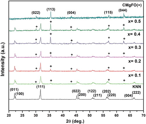
The x-ray diffractograms of (1-x)KNN-xCMgFO (where x = 0.0, 0.1, 0.2, 0.3, 0.4, 0.5 and 1.0) composites are shown in . The sharp and high intense crystalline peaks reveal the crystalline nature of prepared samples. The appearance of the high intense peaks corresponding to 2θ ~ 31° and 35° reveal that both phases (KNN and CMgFO) have also been present in composites. The peak indexing of XRD pattern for KNN reveals the presence of orthorhombic perovskite structure with symmetry of Amm2 space group (ICSD collection code 9533) whereas, CMgFO has been indexed to the cubic structure of CoFe2O4 having Fd-3m space group symmetry (ICSD collection code 39131). The lattice parameters of the individual phases have also been calculated by using Bragg’s Law (EquationEq. 1
(1)
(1) )
Figure 1. XRD patterns of (1-x)KNN-xCMgFO (x = 0.0, 0.1, 0.2, 0.3, 0.4, 0.5 and 1.0) composites
where n = 1, d is the interplanar spacing given by EquationEq. 2(2)
(2) .
Here h, k, l are the miller indices and a, b, c represents the lattice parameters.
The lattice parameters of orthorhombic KNN have been calculated by using peaks (011), (100), (111), (022), and (200) at 2θ = 22.10º, 22.44º, 31.74º, 45.20º, and 45.92º, respectively. While peaks (022) and (113) at 2θ = 30º and 35.42º, respectively, have been used for the cubic CMgFO phase. The values of lattice parameters of KNN and CMgFO are found to be a = 3.964 Å, b = 5.632 Å, c = 5.685 Å and a = 8.391 Å, respectively. XRD spectra of composites indicate the presence of ferroelectric and ferrite phases, without any secondary phase. This confirms that no chemical reaction takes place between constituent phases during high-temperature sintering process. Further, the stoichiometry of the composites has also been explored by EDS analysis (Supporting Fig. S1 and Table S1).
3.2. Microstructural and elemental analysis
The series of SEM micrographs of (1-x)KNN-xCMgFO where x = 0.0, 0.1, 0.2, 0.3, 0.4, 0.5 and 1.0 composites have been represented in . SEM image for KNN reflects the presence of dense microstructure with uniform grains. It can be observed (inset )), that samples have cuboidal-shaped grains, which is a common feature in KNN-based ceramics [Citation23,Citation24]. On the other hand, CMgFO has a bimodal microstructure, consisting of small and large-sized grains. The SEM images of composites reveal the presence of both cuboidal shaped and large agglomerated grains. From SEM images of the composites, it has been observed that ferrite particles are uniformly distributed in the matrix of the ferroelectric material. The distribution of grains corresponding to different phases in the composites has been also confirmed by using the EDS elemental mapping of x = 0.4 composition (Supporting Fig. S2). The grains of larger size CMgFO are due to the agglomeration of small particles during the sintering process (inset )). This may be due to the high surface area of sol-gel synthesized particles, which lead them to interact through weak van der Waals forces, resulting in agglomeration. Besides this, it can also be related to the presence of magnetic moment that may force particles to attract each other, leading to particle coalescence [Citation25]. However, the microstructure consists of randomly oriented and non-uniform (in shape and size) grains.
Figure 2. SEM images of (a) KNN, (1-x)KNN-xCMgFO (b) x = 0.1, (c) x = 0.2, (d) x = 0.3, (e) x = 0.4 and (f) x = 0.5 composites and (g) CMgFO
3.3. Ferroelectric analysis
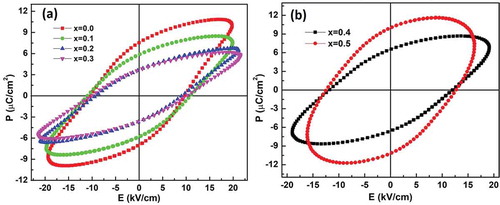
The polarization (P) vs. electric field (E) hysteresis loops for (1-x)KNN-xCMgFO where x = 0.0, 0.1, 0.2, 0.3, 0.4 and 0.5 composites are shown in . The maximum polarization, remanence and coercive field for KNN have been found to be 10.378 μC/cm2, 7.268 μC/cm2 and 10.094 kV/cm, respectively, which may be attributed to B-site off center shift of Nb cation from the centers of the oxygen octahedra [Citation26–29]. The ferroelectric nature of KNN is also reflected in the PE loops of the composites. However, the ferroelectric nature of composites is lower down with the decrease in KNN content upto x = 0.3. This is also evident from decreasing values of maximum polarization and remanence as given in . The reason for the change in the ferroelectricity of composites can be related to the presence of CMgFO. With the increasing ferrite content, the ferroelectric nature of the composites becomes weaker. This is due to leakage of charge by conduction through the ferrite phase via Fe3+/Fe2+ ions [Citation24]. The lossy P-E loop for x = 0.4 & 0.5 shows that the composite sample is no longer a ferroelectric composite and the materials with such polarization curves are commonly known as “lossy”, indicating the loss of charge through the sample.
Table 1. The values of maximum polarization (Pmax), remanent polarization (Pr), coercive field (Ec), dielectric constant (ε') and tangent delta (Tanδ) for composites
Figure 3. P-E hysteresis loops of (1-x)KNN-xCMgFO (a) x = 0.0, 0.1, 0.2, 0.3 (b) x = 0.4, 0.5 composites
3.4. Magnetic properties
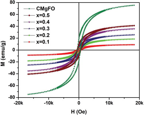
The magnetization (M) versus magnetic field (H) hysteresis loops for (1-x)KNN-xCMgFO where x = 0.1, 0.2, 0.3, 0.4, 0.5 and 1.0 composites are shown in . All the composites exhibit ferromagnetic hysteresis loops, indicating the presence of an ordered magnetic structure. The saturation magnetization ~75 emu/g of CMgFO reveals the dominance of the ferromagnetic character of the prepared ferrite. Overall magnetization in cobalt ferrite is a result of antiparallel coupling between the tetrahedral (A) and octahedral (B) sites in spinel structure [Citation30]. From the M-H curves of the composites, it has been observed that there is a regular decrease in the magnetization of composites with decreasing CMgFO content. The values of saturation magnetization (Ms), remanent magnetization (Mr) and coercivity (Hc) for different compositions are given in . The values of Ms and Mr have been found to increase with an increase in ferrite content. The reason for this is clear from the fact that with the addition of CMgFO, there is an increase in the concentration of Fe3+ ions, which further, increases the exchange interaction mechanism occurring between metal ions in A and B sites. This in turn is responsible for the increase in saturation magnetization [Citation31]. Hc values have been found to increase with increase in the concentration of ferroelectric phase. This is due to increasing hindrance in domain wall motion caused by the presence of non-magnetic ferroelectric phase [Citation32].
Table 2. Values of remanent magnetization (Mr), saturation magnetization (Ms), coercivity (Hc) and magnetodielectric (MD) for different compositions
Figure 4. Magnetic hysteresis curves of CMgFO and (1-x)KNN-xCMgFO composites (x = 0.1, 0.2, 0.3, 0.4 and 0.5)
3.5. Dielectric properties
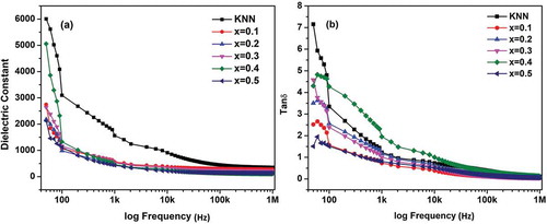
The room temperature dielectric measurements (dielectric constant (ε') and dielectric loss (Tanδ) versus frequency) of (1-x)KNN-xCMgFO where x = 0.0, 0.1, 0.2, 0.3, 0.4 and 0.5 composites are shown in (a) and 5 (b). The dielectric constant of all compositions decreases rapidly with increasing frequency and then becomes constant at higher frequencies, which is the general behavior of the dielectric materials. This dispersion behavior is due to the fact that some of the polarizations (space charge and dipolar polarization) are unable to follow the variation in the electric field at high frequencies, which results in the decrease in net polarization due to which both dielectric constant and dielectric loss decreases [Citation33,Citation34]. Similar frequency dispersion can also be observed for dielectric loss as shown in ). In addition to this, the frequency dispersion behavior of composites can be explained on the basis of Maxwell-Wagner polarization mechanism in accordance with Koop’s phenomenological theory [Citation35,Citation36]. In the presence of an external electric field, space charges get accumulated at the interfaces of KNN and CMgFO due to their different permittivity and conductivity. This space charge polarization leads to high values of dielectric constant at low frequencies [Citation37,Citation38]. It is also observed that dielectric constant decreases and loss tangent increases with increasing ferrite concentration, except for x = 0.5 (). This could be attributed to the low value of dielectric constant and high dielectric loss of the conducting ferrite phase. Apart from this, other possible sources of dielectric losses are relaxation and resonance loss [Citation39]. The relaxation loss can be attributed to the relaxation polarizations which are not able to follow the external applied electric field variations. However, the resonance loss contributes least to the dielectric loss, which can be related to the vibrations of the electrons, atoms or molecules, generating the heating effect, during resonance absorption.
Figure 5. Room temperature (a) dielectric constant and (b) dielectric loss (Tanδ) versus frequency plots of KNN and (1-x)KNN-xCMgFO composites with x = 0.1, 0.2, 0.3, 0.4 and 0.5
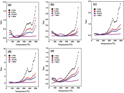
The temperature dependence of dielectric profile of (1-x)KNN-xCMgFO where x = 0.1, 0.2, 0.3, 0.4 and 0.5 composites in the temperature range from room temperature to 500°C has been shown in . The dielectric constant first increases continuously with increasing temperature upto certain maximum value and then decreases with further increase in temperature revealing a phase transition commonly known as ferroelectric phase transition and temperature corresponding to this transition is known as ferroelectric transition temperature and is represented as TCFE. The temperature-dependent dielectric profile shows two transitions of TC1FE and TC2FE at T ~ 210 and 410 °C. The TC1FE ~210°C is corresponding to orthorhombic to tetragonal phase transition whereas TC2FE ~410°C is tetragonal to cubic phase transition [Citation40,Citation41]. The above-mentioned dielectric anomalies are also visible in the dielectric loss as shown in . Further, it can be observed that dielectric loss increases with temperature, which is due to an increase in the hopping of electrons between Fe3+ and Fe2+ ions, resulting in space charge conduction [Citation42].
Figure 6. Temperature dependence of dielectric constant of (1-x)KNN-xCMgFO composites with (a) x = 0.1 (b) x = 0.2 (c) x = 0.3 (d) x = 0.4 and (e) x = 0.5
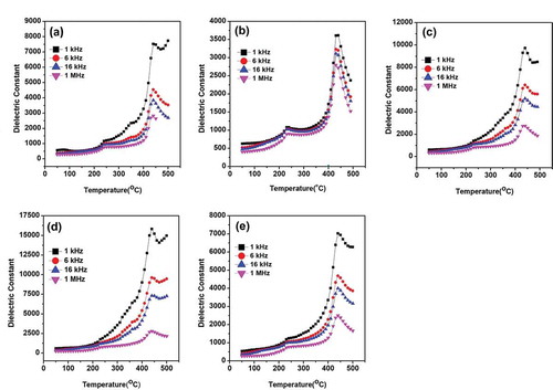
Figure 7. Variation of dielectric loss (Tanδ) with temperature for (1-x)KNN-xCMgFO composites with (a) x = 0.1 (b) x = 0.2 (c) x = 0.3 (d) x = 0.4 and (e) x = 0.5
3.6. Magnetodielectric properties
To explore the magnetoelectric properties in terms of magnetodielectric response, the frequency dependence capacitance profile in the presence and absence of magnetic field has been performed. The variation of dielectric constant (ε') (calculated from capacitance) with the magnetic field is direct evidence of magnetodielectric effect (MD).
MD (in terms of percentage) has been calculated using EquationEq. 3(3)
(3) [Citation43]:
where; MD is the magnetodielectric coefficient, ϵ(H) and ϵ(0) are values of dielectric constant at magnetic field values H and zero, respectively, at the same frequency. shows the variation of MD response with magnetic field at 2 kHz. The values of MD for the composites are given in .
Figure 8. Variation of MD with magnetic field (H) for (a) (1-x)KNN-xCMgFO (x = 0.1, 0.2, 0.3, 0.4 and 0.5) composites and (b) 0.6KNN-0.4CMgFO at different frequencies
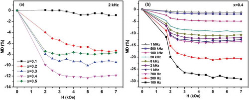
It is clear from ) that with an increase in the magnetic field, MD increases in a negative direction and gets saturated at higher values of the magnetic field. This indicates the presence of negative coupling in the composites [Citation44]. It can be seen that the values of MD increase from x = 0.1 to 0.4 and reaches a maximum of ~ −10% for x = 0.4, which is relatively higher comparing to recently reported KNN-based multiferroic composites, indicating strong ME coupling effect [Citation15,Citation19,Citation29,Citation45]. The magnetodielectric response of composite sample for x = 0.4 at certain frequencies individually shown in ). The increase in MD with increasing ferrite content may be attributed to an increase in magnetostriction and the maximum surface area of contact between two ferroic phases. The induced strain in ferrite phase with the application of the magnetic field produces the stress in the ferroelectric phase due to which electric dipoles get aligned, leading to modification in dielectric properties of the composites [Citation46,Citation47].
4. Conclusion
The multiferroic composites of (1-x)K0.5Na0.5NbO3-xCo(Mg0.05Fe1.95)O4 (where x = 0.0, 0.1, 0.2, 0.3, 0.4 0.5 and 1.0) have been successfully synthesized. The structures of prepared KNN and CMgFO are perovskite orthorhombic and spinel cubic, without any secondary phase. The appearance of both ferroelectric and ferromagnetic hysteresis loops up to x = 0.3 has revealed the multiferroic behavior in composites, whereas lossy P-E hysteresis loops have been obtained for x = 0.4 and 0.5. The dielectric constant of all composites has shown a decreasing trend with frequency due to the polarization relaxation phenomena. The larger loss with increasing CMgFO concentration can be attributed to the more relaxation polarization and loss due to the conductive nature of ferrite. The temperature-dependent dielectric profile shows two transition temperatures ~210°C and ~410°C corresponding to orthorhombic to tetragonal and tetragonal to cubic phase transitions of KNN, respectively. The CMgFO shows the highest saturation magnetization (Ms) of ~75 emu/g, while the minimum Ms ~9 emu/g has been observed for x = 0.1 composite. The variation in dielectric constant with magnetic field confirms the magnetodielectric (MD) effect which can be attributed to strain mediated stress with applied magnetic field in composites. The maximum value of MD response is ~ −10% for x = 0.4 at 2 kHz, which is an indication of negative MD effect, but simultaneously, it has shown the poor insulating behavior as compared to other composites, indicating the importance of present research work.
Supplemental Material
Download MS Word (514.5 KB)Supplementary material
Supplemental data for this article can be accessed here.
Disclosure statement
No potential conflict of interest was reported by the authors.
Additional information
Funding
References
- Scott JF. Applications of magnetoelectrics. J Mater Chem. 2012;22(11):4567–4574.
- Schmid H. Multi-ferroic magnetoelectrics. Ferroelectrics. 1994;162(1):317–338.
- Debye P. Comment on some new experiments on a magneto-electrical directing effect. Zeitschrift für Physik. 1926;36(4):300–301.
- Wang Y, Hu J, Lin Y, et al. Multiferroic magnetoelectric composite nanostructures. NPG Asia Mater. 2010;2(2):61–68.
- Nan CW, Bichurin MI, Dong S, et al. Multiferroic magnetoelectric composites: historical perspective, status, and future directions. J Appl Phys. 2008;103(3):1.
- Nan CW. Magnetoelectric effect in composites of piezoelectric and piezomagnetic phases. Phys Rev B. 1994;50(9):6082.
- Ortega N, Bhattacharya P, Katiyar RS, et al. Multiferroic properties of Pb(Zr,Ti)O3∕ CoFe2O4 composite thin films. J Appl Phys. 2006;100(12):126105.
- Chunyue L, Xu R, Gao R, et al. Structure, dielectric, piezoelectric, antiferroelectric and magnetic properties of CoFe2O4–PbZr0.52Ti0.48O3 composite ceramics. Mater Chem Phys. 2020;249:123144.
- Lopatin S, Lopatina I, Lisnevskaya I. Magnetoelectric PZT/ferrite composite material. Ferroelectrics. 1994;162(1):63–68.
- Bozorth RM, Walker JG. Magnetostriction of single crystals of cobalt and nickel ferrites. Phys Rev. 1952;88(5):1209.
- Shrout TR, Zhang SJ. Lead-free piezoelectric ceramics: alternatives for PZT? J Electroceram. 2007;19(1):113–126.
- Zheng H, Wang J, Lofland SE, et al. Multiferroic BaTiO3-CoFe2O4 nanostructures. Science. 2004;303(5658):661–663.
- Upadhyay SK, Reddy VR, Lakshmi N. Study of (1−x)BaTiO3–xNi0.5Zn0.5Fe2O4 (x = 5, 10 and 15%) magneto-electric ceramic composites. J Asian Ceram Soc. 2013;1(4):346–350.
- Zhang RF, Deng CY, Ren L, et al. Ferroelectric, ferromagnetic, and magnetoelectric properties of multiferroic Ni0.5Zn0.5Fe2O4–BaTiO3 composite ceramics. J Electron Mater. 2014;43(4):1043–1047.
- He S, Liu G, Xu J, et al. Magnetodielectric effect in lead-free multiferroic CoFe2O4/K0.5Na0.5NbO3 bilayers. Mater Lett. 2012;89:159–162.
- Sowmya NS, Srinivas A, Reddy KV, et al. Magnetoelectric coupling studies on (x)(0.5BZT-0.5BCT)-(100-x)NiFe2O4 [x=90−70wt%] particulate composite. Ceramic Int. 2017;43(2):2523–2528.
- Gao R, Qin X, Zhang Q, et al. A comparative study of the dielectric, ferroelectric and anomalous magnetic properties of Mn0.5Mg0.5Fe2O4/Ba0.8Sr0.2Ti0.9Zr0.1O3 composite ceramics. Mater Chem Phys. 2019;232:428–437.
- Shamim MK, Sharma S, Choudhary RJ. Role of ferrite phase on the structure, dielectric and magnetic properties of (1-x)KNNL/xNFO composites ceramics. J Magn Magn Mater. 2019;469:1–7.
- Shamim MK, Sharma S, Choudhary RJ. Lead-free (K, Na, Li) NbO3/NiFe2O4 thin films by pulsed laser deposition: structure, dielectric, magnetic and magnetodielectric behavior. J Alloy Compd. 2019;794:534–541.
- Shamim MK, Sharma S, Choudhary RJ. Structure, electrical and magnetic properties of Co0.8Zn0.2Fe2O4/(K0.47Na0.47Li0.6)NbO3 bilayered thin films grown by pulsed laser deposition. J Appl Phys. 2019;126(13):134104.
- Fu J, Zuo R, Xu Z. High piezoelectric activity in (Na,K)NbO3 based lead-free piezoelectric ceramics: contribution of nanodomains. Appl Phys Lett. 2011;99(6):062901.
- Anantharamaiah PN, Joy PA. Enhancing the strain sensitivity of CoFe2O4 at low magnetic fields without affecting the magnetostriction coefficient by substitution of small amounts of Mg for Fe. Phys Chem Chem Phys. 2016;18(15):10516–10527.
- Birol H, Damjanovic D, Setter N. Preparation and characterization of (K0.5Na0.5)NbO3 ceramics. J Eur Ceram Soc. 2006;26(6):861–866.
- Fisher JG, Kang SJ. Microstructural changes in (K0.5Na0.5)NbO3 ceramics sintered in various atmospheres. J Eur Ceram Soc. 2009;29(12):2581–2588.
- Kurian M, Thankachan S, Nair DS, et al. Structural, magnetic, and acidic properties of cobalt ferrite nanoparticles synthesized by wet chemical methods. J Adv Ceram. 2015;4(3):199–205.
- Ivliev MP, Raevskaya SI, Raevskiĭ IP, et al. Formation of ferroelectric phases in KNbO3 and other niobates with perovskite structure. Phys Solid State. 2007;49(4):769–779.
- Megaw HD. Origin of ferroelectricity in barium titanate and other perovskite-type crystals. Acta Crystallogr. 1952;5(6):739–749.
- Shalini K, Giridharan NV. Structural, dielectric and magnetic properties of K0.5Na0.5NbO3 and K0.5Na0.5Nb0.975Co0.025O3 lead free ceramics. Ferroelectrics. 2017;518(1):52–58.
- Lekha CC, Kumar AS, Vivek S, et al. Room temperature magnetoelectric properties of lead-free alkaline niobate based particulate composites. Ceram Int. 2019;45(7):8115–8122.
- Smit J, Wijn HP. Physical properties of ferrites. In: Advances in electronics and electron physics. Vol. 6. Academic Press, New York; 1954. p. 69–136.
- Xue Y, Xu R, Wang Z, et al. Effect of magnetic phase on structural and multiferroic properties of Ni1−xZnxFe2O4/BaTiO3 composite ceramics. J Electron Mater. 2019;48(8):4806–4817.
- Chen W, Wang ZH, Zhu W, et al. Ferromagnetic, ferroelectric and dielectric properties of Pb (Zr0.53Ti0.47)O3/CoFe2O4 multiferroic composite thick films. J Phys D Appl Phys. 2009;42(7):075421.
- Bammannavar BK, Naik LR. Electrical properties and magnetoelectric effect in (x)Ni0.5Zn0.5Fe2O4+(1−x)BPZT composites. Smart Mater Struct. 2009;18(8):085013.
- Gao R, Qin X, Zhang Q, et al. Enhancement of magnetoelectric properties of (1-x)Mn0.5Zn0.5Fe2O4-xBa0.85Sr0.15Ti0.9Hf0.1O3 composite ceramics. J Alloy Compound. 2019;795:501–512.
- Wagner KW. On the theory of imperfect dielectrics. Ann Phys. 1913;345(5):817–855.
- Koops CG. On the dispersion of resistivity and dielectric constant of some semiconductors at audio frequencies. Phys Rev. 1951;83(1):121.
- Ciomaga CE, Neagu AM, Pop MV, et al. Ferroelectric and dielectric properties of ferrite-ferroelectric ceramic composites. J Appl Phys. 2013;113(7):074103.
- Xu R, Wang Z, Gao R, et al. Effect of molar ratio on the microstructure, dielectric and multiferroic properties of Ni0.5Zn0.5Fe2O4-Pb0.8Zr0.2TiO3 nanocomposite. J Mater Sci Mater Electron. 2018;29(19):16226–16237.
- Gao R, Zhang Q, Xu Z, et al. A comparative study on the structural, dielectric and multiferroic properties of Co0.6Cu0.3Zn0.1Fe2O4/Ba0.9Sr0.1Zr0.1Ti0.9O3 composite ceramics. Compos Part B-Eng. 2019;166:204–212.
- Kumar Y, Yadav KL, Shah J, et al. Study of structural, dielectric, electric, magnetic and magnetoelectric properties of K0.5Na0.5NbO3−Ni0.2Co0.8Fe2O4 composites. Ceram Int. 2017;43(16):13438–13446.
- Li JF, Wang K, Zhu FY, et al. (K,Na)NbO3‐Based Lead‐Free Piezoceramics: fundamental Aspects, Processing Technologies, and Remaining Challenges. J Am Ceram Soc. 2013;96(12):3677–3696.
- Rani J, Yadav KL, Prakash S. Dielectric and magnetic properties of xCoFe2O4–(1− x)[0.5 Ba (Zr0.2Ti0.8)O3–0.5(Ba0.7Ca0.3)TiO3] composites. Mater Res Bull. 2014;60:367–375.
- Catalan G. Magnetocapacitance without magnetoelectric coupling. Appl Phys Lett. 2006;88(10):102902.
- Pradhan DK, Puli VS, Kumari S, et al. Studies of phase transitions and magnetoelectric coupling in PFN-CZFO multiferroic composites. J Phys Chem C. 2016;120(3):1936–1944.
- Rakhikrishna R, Isaac J, Philip J. Magneto-electric characterization of x(Na0.5K0.5)0.94Li 0.06NbO3-(1-x)NiFe2O4 composite ceramics. J Electroceram. 2015;35(1–4):120–128.
- Samad R, Want B. Magnetic field control of electric properties in gadolinium doped BaTiO3–CoFe2O4 particulate multiferroic composites. Mater Res Express. 2019;6(6):066310.
- Palkar VR, Kundaliya DC, Malik SK, et al. Magnetoelectricity at room temperature in the Bi0.9−xTbxLa0.1FeO3 system. Phys Rev B. 2004;69(21):212102.