
ABSTRACT
Aerosol deposition (AD) is a ceramics coating technology that can be used at room temperature. AD does not use organic binders for the ceramics coating process, which reduces the amount of exhaust carbon dioxide. Additionally, AD realize fast and wide-area ceramics coating without heating the substrate. Thus, AD is an environmentally friendly ceramics coating process. AD has been already applied to various research fields including energy conversion devices such as rechargeable lithium-ion batteries and solid oxide fuel cells. Unique properties of AD are effective to investigate the fundamental properties of oxide-based all-solid-state batteries (Ox-SSBs) and possibly their productions. This paper reviews developments of Ox-SSBs using AD, mainly presenting our research.
1. Introduction
All-solid-state batteries using oxide-based solid electrolytes (Ox-SSBs) are potential next-generation rechargeable batteries that can realize safety and high energy density. Although the lithium ion (Li+) conductivity of oxide-based solid electrolytes is generally inferior to that of sulfide-based solid electrolytes, several oxide-based solid electrolytes have achieved a Li+ conductivity of 1.10−3 S cm−1 at 25°C [Citation1–3]. Considering that the Li+ transport number of solid electrolytes is ~1, the effective Li+ conductivity is in the same order as that of organic liquid electrolytes. Therefore, the practical Li+ conductivity of such high Li+ conductive oxide-based solid electrolytes is comparable with that of liquid electrolytes. Till date, the application of oxide-based solid electrolytes has been successful in small-sized Ox-SSBs [Citation4,Citation5]. A drawback for developing large-sized Ox-SSBs originates from issues of the interface junction. The majority of oxide-based solid electrolytes with high Li+ conductivities are prepared via sintering at a high temperature of ~1000°C and they are hard and fragile materials. Therefore, a well-adhered electrode–solid electrolyte interface cannot be formed only by mixing and pressing the electrode active materials (Li insertion materials such as LiCoO2) and solid electrolytes. This situation is quite different from all-solid-state batteries using ductile sulfide-based solid electrolytes [Citation6,Citation7]. Therefore, sintering the electrode active material and solid electrolyte can practically induce well-adhered interface bonding.
The driving forces for ceramics densification are 1) a decrease in surface energy, 2) pressure application, and 3) chemical reaction (ΔG0 = −RT ln Keq, where Keq is the equilibrium constant of the reaction) [Citation8]. When an oxide-based solid electrolyte and electrode active material are mixed and sintered at a high temperature, a highly resistive material is often formed by chemical reactions through mutual diffusion around the interface. The selection of appropriate materials with a small Keq or sintering at a low temperature can effectively overcome this chemical reaction problem. Aerosol deposition (AD) introduced herein is a ceramics coating technology used at room temperature that can reduce the driving force of chemical reactions.
2. Brief introduction of AD
shows a schematic of the AD system. AD uses powder of coating materials as a source substance. A powder is stored in a pot (aerosol pot), which is connected to a vacuum evacuated chamber via a nozzle. When a carrier gas is flowed into the aerosol pot, an aerosol is generated. The aerosol is sprayed onto the substrate held in the chamber via the nozzle. The substrate is moved back and forth during the deposition and is typically not heated. This simple apparatus enables fast and wide-area ceramics coating.
Figure 1. Schematic image of an AD system.
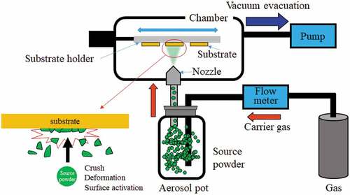
The room temperature ceramics coating phenomena of AD has been explained by room temperature impact consolidation (RTIC), which differs from thermal spraying coating [Citation9]. The RTIC occurs through several mechanisms, including plastic particle deformation. The detailed mechanisms are beyond the scope of this paper and are described in appropriate review papers [Citation10,Citation11]. Herein, the impact of the surface state of source particles will be discussed. As mentioned, the release of surface energy is a driving force for ceramics densification. In the case of AD, the surface energy of the source particle is activated through 1) the exposure of new surfaces with crushing and deformation of source powders [Citation9,Citation11] and 2) local sputtering owing to the crushing of charged source powders [Citation12]. During AD, the powder is sprayed onto the substrate at high velocity, which applies continuous pressure to the substrate and contributes to the film densification.
There is an appropriate particle size range for AD, which is typically submicron- to micron-sized (0.2–2 μm). Particles smaller than this size produce a compressed powder coating layer, whereas particles greater than this size do not form a coating layer [Citation10,Citation11]. When the particle surface is initially coated by another material, the adhesive properties are largely improved in some cases. Consequently, even when 10-μm diameter particles are used as the source powders, a dense ceramics coating layer is formed that can function as an Ox-SSB electrode material [Citation13]. These results indicate that the surface state of the source powders is an important factor for enhancing the room temperature ceramics coating.
AD can achieve large-area and fast coating of ceramics and has been applied to various devices and materials, such as lithium-ion batteries [Citation14–17], all-solid-state batteries [Citation18–20], solid oxide fuel cells [Citation21,Citation22], piezoelectric materials [Citation23], ferroelectric materials [Citation24], and hard coating materials [Citation25]. Recently, Y2O3 films prepared using AD were commercialized as excellent plasma-resistive films for semiconductor manufacturing equipment [Citation26]. Because resultant AD coating films are composed of small particles (typically a few tens of nm), mechanical toughness is expected based on the Hall–Petch relationship [Citation27]. However, the powder utilization ratio strongly depends on the particle species, and the crystallinity of the resultant films generally degrades compared with that of the source powders. These create unique advantages as well as crucial problems for the commercial application of AD.
3. Applications of AD for Ox-SSBs
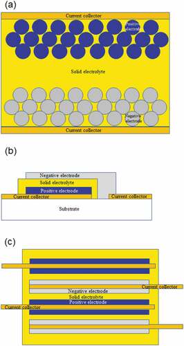
Ox-SSBs are classified into three types based on the structure: bulk, thin-film, and multilayered, as shown in . Bulk-type Ox-SSBs ()) resemble a conventional lithium-ion battery; however, the organic liquid electrolyte is replaced by a solid electrolyte [Citation6,Citation7]. For the preparation of bulk-type Ox-SSBs, powder materials are applied for both electrodes and the solid electrolytes, and their composites are generally prepared using a sintering process. It is expected that bulk-type Ox-SSBs will be applied as power sources for large-sized devices, such as electric vehicles. Thin-film-type Ox-SSBs ()) are prepared by sequentially stacking the electrode and solid electrolyte thin-film layers. The thin-film-type is expected to be a power source of small-sized devices, such as the Internet of things and sensing devices. Multilayered-type Ox-SSBs ()) were recently commercialized by a ceramics company in Japan [Citation4,Citation5]. For the synthesis process, green sheets of the electrode, solid electrolyte, and current collector (CC) layers are multilayered and cosintered. The multilayer-type capacity is currently intermediate between the bulk-type and thin-film-type. AD can be applied for the development of these types of Ox-SSBs and has already been applied to prepare electrode layers [Citation14–16], solid electrolyte layers [Citation17,Citation18], electrode–solid electrolyte composite layers [Citation20], and flexible all-solid-state battery systems [Citation28].
Figure 2. Schematic of three types of Ox-SSBs (a) bulk-type, (b) thin-film-type, and (c) multilayered-type.
3.1. Preparation of electrode–solid electrolyte composite
An electrode–solid electrolyte composite electrode is required in bulk-type Ox-SSBs ()). Such composite electrode layers were prepared using AD. In this case, it was effective to use electrode–solid electrolyte mixed powders as the source powders. An electrode material of LiNi1/3Co1/3Mn1/3O2 (NMC) was used as the mother powder (average particle size: 10 μm) and a crystalline-glass solid electrolyte (Li–Al–Ge–Ti–P–O (LATP), average particle diameter: 0.5 μm, Ohara Inc.) was used as subparticles [Citation29]. When these two powders were mixed by mechanical mixing (Hosokawa Micron: Nobiruta), LATP-dispersed NMC particles were produced. ) shows the SEM images of the LATP-dispersed NMC powders, in which LTP-x represents the mixed powder of NMC:LATP = 100:x (w/w). The LATP coverage ratio increased with the increase in x and became saturated at ca. 70% ()) over x = 5. The LTP-x powders provided NMC–LATP composite electrodes using AD ()). The thickness of the composite electrode increased with x; however, excessive LATP mixing (x > 10) yielded a compacted powder layer with reduced density ()). In the case of x = 0, the 10-μm particle size of the NMC mother powder was too large for AD deposition and the electrode layer was barely formed [Citation13]. These results demonstrate that the surface state of the source particle largely influences the ceramics coating by AD. Based on these results, an Ox-SSB was fabricated using LTP-5, which allowed the formation of dense and relatively thick films ()). The thickness of the mutual diffusion layer around the NMC–LATP interface inside the composite electrode was <5 nm, which was thinner than the NMC film (20 nm) deposited at 700°C on the LATP substrate using the pulsed laser deposition method. ) shows the results of the resultant Ox-SSB (Li/LLZ/NMC–LATP). A NMC–LATP composite electrode layer with a thickness of ca. 20 μm was formed on a sintered LLZ substrate and the battery showed stable charge–discharge reactions at 100°C.
Figure 3. (a) SEM images of LATP-dispersed NMC particles, where LTP-x (x = 0, 2, 5, 10, and 20) denotes the powders prepared by NMC:LATP = 100:x (w/w). (b) Surface coverage ratios of LATP in LTP-x powders. (c) Cross-sectional SEM images of NMC–LATP composite films prepared using LTP-x on Si substrates. (d) Relationship between film thickness and NMC amount in the film against x in LTP-x as the source powders. (e) (Top) cross-sectional SEM image of NMC–LATP composite film prepared using LTP-5 on LLZ substrate. (Middle) charge–discharge curves of Li/LLZ/NMC–LATP battery at 100°C. (Bottom) variation of discharge capacities with cycles at different current densities of 50–1000 μA cm−2 (Reprinted from [29] with permission from Elsevier).
![Figure 3. (a) SEM images of LATP-dispersed NMC particles, where LTP-x (x = 0, 2, 5, 10, and 20) denotes the powders prepared by NMC:LATP = 100:x (w/w). (b) Surface coverage ratios of LATP in LTP-x powders. (c) Cross-sectional SEM images of NMC–LATP composite films prepared using LTP-x on Si substrates. (d) Relationship between film thickness and NMC amount in the film against x in LTP-x as the source powders. (e) (Top) cross-sectional SEM image of NMC–LATP composite film prepared using LTP-5 on LLZ substrate. (Middle) charge–discharge curves of Li/LLZ/NMC–LATP battery at 100°C. (Bottom) variation of discharge capacities with cycles at different current densities of 50–1000 μA cm−2 (Reprinted from [29] with permission from Elsevier).](/cms/asset/2a53c6d0-62e6-433f-aceb-dd0daf7c1f39/tace_a_2163080_f0003_oc.jpg)
It is possible to fabricate similar composite electrodes using other electrode materials. An example is LiNi0.5Mn1.5O4 (LNM), a 5 V-class cathode active material [Citation30]. ) shows the SEM image of the LNM mother powder, while ) shows the cross-sectional SEM image of the composite electrode. The LNM was a spinel-structured material and the mother powder showed facet on the surface. The LATP-dispersed LNM particles were sprayed onto the Pt substrate to form the LNM–LATP composite electrode; however, the Pt substrate surface became extremely deformed. When solid electrolyte sheets were used as substrates, the sheets cracked. Although the particle diameters of the mother powders were similar, the substrate deformation properties and the damage to the substrates differed according to the powder species. It is believed that the LNM particles were formed as highly crystalline primally particles and subsequently deformation supplied a large amount of energy to the substrate. The LNM–LATP composite electrode with a thickness of ca. 10 μm ()) was combined with a lithium phosphorus oxynitride glass electrolyte (LiPON) and Li (negative electrode) to prepare a 5 V-class all-solid-state battery. Operating at 100°C, the Ox-SSBs delivered a discharge capacity of 100 mAh g−1 at 10 μA cm2. Although the charge–discharge reactions were repeated ()), the capacity degraded with the repetition of cycles. No degradation occurred in the thin-film-type SSB using an LNM thin film with a thickness of ca. 30 nm [Citation31], although the charge–discharge reactions were repeated over a wider potential range at the same temperature. After the charge–discharge reaction, the LNM–LATP composite electrode was extremely brittle. The volume change of NMC is almost 0% during the charge–discharge reactions shown in ) [Citation32], whereas that of LNM is ca. 6.5% ()) [Citation33]. One reason for the difference in stability between these two electrodes will be the difference in volume change during the charge–discharge reactions. Therefore, the electrode volume change is an important factor for stable charge–discharge properties in Ox-SSBs [Citation20].
Figure 4. (a) SEM image of LNM source powder. (b) Cross-sectional SEM image of an LNM–LATP composite electrode formed on Pt substrate. (c) Cross-sectional SEM image of LNM–LATP composite electrode. (d) Discharge curves of Li/LiPON/LNM–LATP composite electrodes at 100°C. Charging current density was fixed at 10 μA cm−2 while the discharge current densities were varied from 10 to 200 μA cm−2. (e) Variation of discharge capacity of Li/LiPON/LNM–LATP (composite electrode) with cycles at 25°C–100°C at 10 μA cm−2. The discharge capacity variations of a thin-film-type Ox-SSB of Li/LiPON/LNM (thin-film, 30 nm in thickness) are also shown as the reference (Reprinted from [30] with permission from Elsevier).
![Figure 4. (a) SEM image of LNM source powder. (b) Cross-sectional SEM image of an LNM–LATP composite electrode formed on Pt substrate. (c) Cross-sectional SEM image of LNM–LATP composite electrode. (d) Discharge curves of Li/LiPON/LNM–LATP composite electrodes at 100°C. Charging current density was fixed at 10 μA cm−2 while the discharge current densities were varied from 10 to 200 μA cm−2. (e) Variation of discharge capacity of Li/LiPON/LNM–LATP (composite electrode) with cycles at 25°C–100°C at 10 μA cm−2. The discharge capacity variations of a thin-film-type Ox-SSB of Li/LiPON/LNM (thin-film, 30 nm in thickness) are also shown as the reference (Reprinted from [30] with permission from Elsevier).](/cms/asset/b88f5e98-01a2-498e-b796-c06da4fcd02a/tace_a_2163080_f0004_oc.jpg)
3.2. Preparation of electrode–solid electrolyte model layers
In the case of multilayered Ox-SSBs, the electrode and solid electrolyte green sheet layers are sequentially stacked and co-sintered. Although there are technical difficulties associated with the formation of such multilayered Ox-SSBs using AD, it is possible to fabricate an electrode–solid electrolyte single layer to investigate how interfacial resistance varies with the sintering temperature. Herein, the LCO–LATP single stack prepared using AD is introduced [Citation34]. To fabricate the LCO layer directly on LATP using AD, an appropriate size of LCO particles is required [Citation9–11]. We prepared spherical LCO particles of ca. 2 μm in diameter using the coprecipitation method ()) [Citation35]. ) shows a cross-sectional SEM image of an LCO film deposited on an LATP sheet (150 μm in thickness, Ohara Inc.). An LCO film with a thickness of ca. 1 μm was formed. ) shows the Raman spectra of the LCO films on LATP sheets annealed at different temperatures. The LCO showed two Raman peaks (A1g (596 cm−1) and Eg (486 cm−1) [Citation36]), and only these peaks were observed for the samples annealed at 300°C. However, once the annealing temperature exceeded 400°C, the Raman peak attributed to Co3O4 appeared at ~700 cm−1, which was caused by the side reaction between LATP and LCO. This Co3O4 peak was observed more prominently with heat treatments above 500°C. This side reaction is triggered by the formation of a nonstoichiometric region of Li around the LCO/LATP interface [Citation37]. The CV measurements clarify that a redox peak of LCO was observed ~3.9 V at a heat treatment temperature of 400°C or lower; however, the peak current decreased and the polarization increased at temperatures of 500°C or higher. The TEM study showed that a metastable interface was formed during room temperature film deposition, and the heat treatment at ~300°C caused structural rearrangement, which improved the bonding properties. Therefore, the LCO/LATP interfacial resistance depends on the annealing temperature and the minimum value was achieved by annealing at 300°C–350°C ()). Based on this knowledge, LCO-LATP composite electrodes with a thickness of about 10 μm were deposited on LLZ substrates and heat-treated at 400°C. ) shows charge-discharge curves of the resultant battery at 100°C. The battery can deliver discharge capacity even at 100 mA cm−2. This annealing temperature is the region of interfacial resistance increasing according to the results of ), while the heat treatment at 400°C showed the best rate capability. In the composite electrode, void amounts decreased from 0.5 vol% to 0.15 vol% by the annealing at 400°C [Citation38]. Thus, both the reduction of interfacial resistance and improvement of ion transport inside the composite electrode through the decrease of void amounts will contribute the rate capability of the composite electrode by the annealing.
Figure 5. (a) SEM image of LCO particles used to prepare LCO–LATP single stack. (b) Cross-sectional SEM image of LCO–LATP stack. (c) Raman spectra of LCO–LATP stacked without (RT) and with annealing at 300°C, 400°C, 500°C, and 600°C. (d) Variation of interfacial resistance at LCO/LATP at 4.0 V (vs. Li/Li+) without and with annealing. (e) Charge–discharge curves of Li/LLZ/LCO–LATP (composite electrode) at 100°C after annealing at 400°C. The charging current density was fixed at 0.05 mA cm−2 while the discharge current density was varied at 0.05–100 mA cm−2 (Reprinted from [34] with permission from John Wiley and Sons).
![Figure 5. (a) SEM image of LCO particles used to prepare LCO–LATP single stack. (b) Cross-sectional SEM image of LCO–LATP stack. (c) Raman spectra of LCO–LATP stacked without (RT) and with annealing at 300°C, 400°C, 500°C, and 600°C. (d) Variation of interfacial resistance at LCO/LATP at 4.0 V (vs. Li/Li+) without and with annealing. (e) Charge–discharge curves of Li/LLZ/LCO–LATP (composite electrode) at 100°C after annealing at 400°C. The charging current density was fixed at 0.05 mA cm−2 while the discharge current density was varied at 0.05–100 mA cm−2 (Reprinted from [34] with permission from John Wiley and Sons).](/cms/asset/3fc6f172-0c45-4efd-8e67-1fd2612cef82/tace_a_2163080_f0005_oc.jpg)
As demonstrated using LCO–LATP, the formation of a low-resistive interface using a common sintering process is difficult with some electrode–solid electrolyte combinations. In this case, inserting another solid electrolyte layer between them was found to be effective. This idea has previously been applied for the surface coating layer on electrode materials in sulfide-based all-solid-state batteries [Citation6] and for the LiPON-coating on LATP to stabilize the Li plating–stripping reactions [Citation39]. Garnet-structured LLZ is a promising solid electrolyte because of its high Li+ conductivity (~10−3 S cm−1 at 25°C) and stability with Li metal [Citation1]. However, LLZ easily reacts with electrode materials during the sintering process at ~700°C and forms a resistive mutual diffusion layer around the interface [Citation40]. Recently, Okumura et al. reported the fabrication of an Ox-SSB using LISICON-structured Li0.5Ge0.5V0.5O4 (LGVO), which is less reactive with LCO-type electrode active materials during sintering [Citation41]. Unfortunately, the ionic conductivity of LGVO is not high (<10−4 S cm−1 at room temperature). One solution to overcome these problems is to fabricate an LLZ substrate coated by an LGVO thin layer. AD is an effective method to fabricate such thin LGVO films. ) shows the surface and cross-sectional SEM images of an LGVO-coated LLZ substrate, in which the LGVO layer with a thickness of 2 μm was formed using AD. Although the crystallinity of the as-prepared LGVO film was extremely degraded, annealing at 700°C–900°C improved the crystallinity and adhesive properties, which were improved through Ge diffusion [Citation42]. Furthermore, the multilayer configuration reduced the cell resistance effectively. ) shows the charge–discharge curves and Nyquist plots of Li/LLZ/LCO at 25°C and ) shows those of Li/LLZ/LGVO/LCO. The LGVO coating reduced the cell resistance by ca. 1/40 compared with the uncoated samples. In the field of multilayered ceramic capacitors, it is possible to control the thickness to 2 m [Citation43]. In addition, LLZ sheets have been prepared using the tape casting method [Citation44]. Thus, we can expect that the LLZ–LGVO multilayer will be a possibility for multilayered ceramic capacitor technology.
Figure 6. (a) (Left) Surface and (right) cross-sectional SEM images of LGVO-coated LLZ substrates. (b) (Left) charge–discharge curves of Li/LLZ/LCO at 25°C (LLZ/LCO was annealed at 700°C). (Right) Nyquist plots of Li/LLZ/LCO at 25°C measured at 3.0 V (blue) and 4.0 V (red). (c) (Left) charge–discharge curves of Li/LLZ/LGVO/LCO at 25°C (LLZ/LGVO/LCO stack was annealed at 700°C). (Right) Nyquist plots of Li/LLZ/LGVO/LCO at 25°C measured at 3.0 V (blue) and 4.0 V (red) (Reprinted from[42] with Copyright 2022 American Chemical Society).
![Figure 6. (a) (Left) Surface and (right) cross-sectional SEM images of LGVO-coated LLZ substrates. (b) (Left) charge–discharge curves of Li/LLZ/LCO at 25°C (LLZ/LCO was annealed at 700°C). (Right) Nyquist plots of Li/LLZ/LCO at 25°C measured at 3.0 V (blue) and 4.0 V (red). (c) (Left) charge–discharge curves of Li/LLZ/LGVO/LCO at 25°C (LLZ/LGVO/LCO stack was annealed at 700°C). (Right) Nyquist plots of Li/LLZ/LGVO/LCO at 25°C measured at 3.0 V (blue) and 4.0 V (red) (Reprinted from[42] with Copyright 2022 American Chemical Society).](/cms/asset/e0a346e9-a6a6-4f58-9597-8df9c2fda3a5/tace_a_2163080_f0006_oc.jpg)
3.3. Application to a unique thin-film-type Ox-SSB
Thin-film-type Ox-SSBs are prepared via the sequential preparation of a cathode film, an amorphous solid electrolyte (such as LiPON), and a Li metal film on a substrate [Citation45]. Cathode films are crystalline materials; therefore, substrate heating (>500°C) is required. The ionic conductivity of LiPON is ca. 2.10−6 S cm−1 at room temperature. LiPON is one of the few solid electrolytes in which Li plating–stripping reactions occur stably [Citation46]; however, LiPON is crystallized at ca. 300°C, which decreases the ionic conductivity. Thus, the stacking order is limited by crystallization temperature of cathode film and the thermal stability of the LiPON. These layers are generally formed via vacuum evaporation and radio frequency magnetron sputtering. When Li is grown through an electrochemical Li plating reaction during the charging process via a Li+ extraction reaction of the cathode, it is unnecessary to prepare Li metal films using an evaporation method [Citation47]. This can simplify the fabrication process of thin-film-type Ox-SSBs. However, electrochemically grown Li is highly reactive. Such electrochemically grown Li is pure and reacts with residual gas, even inside a scanning electron microscope, forming inactive materials such as LiOH, Li2O, and Li2CO3 [Citation48]. This reduces the Coulombic efficiency of the charge–discharge reactions and degrades battery performance. Sealing materials are required to overcome this problem, for which LiPON has been reported as an effective material [Citation47]. Thus, if a CC/LiPON/cathode laminate is constructed, electrochemically plated Li is sealed between the CC and LiPON, and a stable charge–discharge reaction is expected by eliminating side reactions with residual gases. This inverted stack of thin-film-type Ox-SSBs was prepared using AD, which can be used to fabricate crystalline electrodes at room temperature [Citation49]. ) shows a cross-sectional SEM image of an LCO thin film deposited using AD on a CC/LiPON stack. When this CC/LiPON/LCO stack was charged, Li was electrochemically plated between the CC and LiPON, and Ox-SSBs operating at 4 V were formed. ) shows an example of applying this phenomenon to prepare flexible thin-film-type Ox-SSBs. Notably, these 4-V thin-film-type Ox-SSBs were prepared only using the room temperature process. AD does not require post-annealing for crystalline electrode materials in some cases, and this advantage enables the usage of a flexible CC film such as a copper-deposited Kapton film.
Figure 7. (a) Cross-sectional SEM image of CC/LiPON/LCO stack and (b) Optical image of flexible thin-film-type Ox-SSBs. (Reprinted from [49] with permission from Elsevier) (c) Optical image of electrode–solid electrolyte single stack with wide-area electrode coatings. The substrates are (left) LLZ and (right) LATP (Reprinted from [34] with permission from Elsevier).
![Figure 7. (a) Cross-sectional SEM image of CC/LiPON/LCO stack and (b) Optical image of flexible thin-film-type Ox-SSBs. (Reprinted from [49] with permission from Elsevier) (c) Optical image of electrode–solid electrolyte single stack with wide-area electrode coatings. The substrates are (left) LLZ and (right) LATP (Reprinted from [34] with permission from Elsevier).](/cms/asset/c5ccbece-9a13-4b76-a51b-adff6e4f5406/tace_a_2163080_f0007_oc.jpg)
4. Summary
This paper introduces several examples of how AD can be applied to investigate fundamental properties of three types of Ox-SSBs. AD enables the formation of electrode or electrode–solid electrolyte composite layers at room temperature. This advantage is useful for understanding the mechanism of side reactions during the sintering process. Moreover, AD provides the possibility of developing novel Ox-SSBs, such as inverted stack flexible thin-film-type Ox-SSBs. We have revealed that large-area electrode coating is possible by applying a large-sized AD system ()) [Citation34]. However, further fundamental research is required for commercial applications, such as increasing the transfer ratio of powders to the film, improving homogeneity, keeping crystallinity, et al. These properties are influenced by the parameters of the AD system as well as by the properties of the powders and their surface states. Close collaborating works between these two research fields will be essential to accelerate the commercial application of AD to Ox-SSBs.
Acknowledgments
This work was supported by ALCA-SPRING (JPMJAL1301) and in part by JSPS KAKENHI Number JP19H05813 (Grant-in-Aid for Scientific Research on Innovation Areas “Interface IONICS”).
Disclosure statement
No potential conflict of interest was reported by the author(s).
Additional information
Funding
References
- Murugan R, Thangadurai V, Weppner W. Fast lithium ion conduction in garnet-type Li7La3Zr2O12. Angew Chem Int Ed. 2007;46(41):7778–7781.
- Sun Z, Liu L, Lu Y, et al. Preparation and ionic conduction of Li1.5Al0.5Ge1.5(PO4)3 solid electrolyte using inorganic germanium as precursor. J Eur Ceram Soc. 2019;39(2–3):402–408.
- Inaguma Y, Liquan C, Itoh M, et al. High ionic conductivity in lithium lanthanum titanate. Solid State Commun; 1993;86:689–693.
- https://www.tdk-electronics.tdk.com/en/ceracharge. Accessed: 26 December 2022.
- https://www.murata.com/en-eu/news/batteries/solid_state/2019/0626. Accessed: 26 December 2022.
- Ohta N, Takada K, Zhang L, et al. Enhancement of the high-rate capability of solid-state lithium batteries by nanoscale interfacial modification. Adv Mater. 2006;18(17):2226–2229.
- Sakuda A, Hayashi A, Tatsumisago M. Sulfide solid electrolyte with favorable mechanical property for all-solid-state lithium battery. Sci Rep. 2013;3(1):2261.
- Rahaman MN Sintering of Ceramics Fundamentals. Ceramic processing and sintering Second Edition. USA: Taylor & Francis; 2003. ISBN: 978-0-8247-0988-4.
- Akedo J. Aerosol deposition of ceramic thick films at room temperature: densification mechanism of ceramic layers. J Am Ceram Soc. 2006;89(6):1834–1839.
- Hnaft D, Exner J, Schubert M, et al. An overview of the aerosol deposition method: process fundamentals and new trends in materials applications. J Ceram Sci Technol. 2015;6:147–182.
- Akedo J. Room temperature impact consolidation and application to ceramic coatings: aerosol deposition method. J Ceram Soc Jpn. 2020;128(3):101–116.
- Fuchita E, Tokizaki E, Ozawa E, et al. Appearance of high-temperature phase in zirconia films made by aerosol gas deposition method. J Ceram Soc Jpn. 2011;119(1388):271–276.
- Iwasaki S, Hamanaka T, Yamakawa T, et al. Preparation of thick-film LiNi1/3Co1/3Mn1/3O2 electrodes by aerosol deposition and its application to all-solid-state batteries. J Power Sources. 2014;272:1086–1090.
- Usui H, Kashiwa Y, Iida T, et al. Anode properties of Ru-coated Si thick film electrodes prepared by gas-deposition. J Power Sources. 2010;195(11):3649–3654.
- Inada R, Shibukawa K, Masada C, et al. Characterization of as-deposited Li4Ti5O12 thin film electrode prepared by aerosol deposition method. J Power Sources. 2014;253:181–186.
- Kim I, Park J, Nam T-H, et al. Electrochemical properties of an as-deposited LiFePO4 thin film electrode prepared by aerosol deposition. J Power Sources. 2013;244:646–651.
- Ahn C-W, Choi -J-J, Ryu J, et al. Microstructure and electrochemical properties of iron oxide film fabricated by aerosol deposition method for lithium ion battery. J Power Sources. 2015;275:336–340.
- Ahn C-W, Choi -J-J, Ryu J, et al. Microstructure and ionic conductivity in Li 7 La 3 Zr 2 O 12 film prepared by Aerosol deposition method. J Electrochem Soc. 2015;162(1):A60–A63.
- http://nisri.jp/jisedai/docs/lecture_20101216_akedo.pdf in Japanese. Accessed 26 December 2022.
- Cheng EJ, Kushida Y, Abe T, et al. Degradation mechanism of all-solid-state Li-metal batteries studied by electrochemical impedance spectroscopy. ACS Appl Mater Interfaces. 2022;14(36):40881–40889.
- Choi -J-J, S-H O, Noh H-S, et al. Low temperature fabrication of nano-structured porous LSM–YSZ composite cathode film by aerosol deposition. J Alloys Compd. 2011;509(5):2627–2630.
- Wang S-F, Hsu Y-F, Wang C-H, et al. Solid oxide fuel cells with Sm0.2Ce0.8O2−δ electrolyte film deposited by novel aerosol deposition method. J Power Sources. 2011;196(11):5064–5069.
- Akedo J, Lebedev M. Microstructure and electrical properties of lead zirconate titanate(Pb(Zr 52 /Ti 48)O 3) thick films deposited by Aerosol deposition method. Jpn J Appl Phys. 1999;38(9S):5397–5401.
- Kim H-K, Lee S-H, Kim SI, et al. Dielectric strength of voidless BaTiO 3 films with nano-scale grains fabricated by aerosol deposition. J Appl Phys. 2014;115(1):014101.
- Lebedev M, Akedo J, Ito T. Substrate heating effects on hardness of α -Al2O3 thick film formed by aerosol deposition method. J Cryst Growth. 2005;275(1–2):e1301–e1306.
- https://jp.toto.com/products/ceramics/ad/ in Japanese . Accessed: 26 December 2022.
- Ryou H, Drazin JW, Wahl KJ, et al. Below the hall–Petch limit in nanocrystalline ceramics. ACS Nano. 2018;12(4):3083–3094.
- Gockeln M, Glenneberg J, Busse M, et al. Flame aerosol deposited Li4Ti5O12 layers for flexible, thin film all-solid-state Li-ion batteries. Nano Energy. 2018;49:564–573.
- Kato T, Iwasaki S, Ishii Y, et al. Preparation of thick-film electrode-solid electrolyte composites on Li7La3Zr2O12 and their electrochemical properties. J Power Sources. 2016;303:65–72.
- Iriyama Y, Wadaguchi M, Yoshida K, et al. 5V-class bulk-type all-solid-state rechargeable lithium batteries with electrode-solid electrolyte composite electrodes prepared by aerosol deposition. J Power Sources. 2018;385:55–61.
- West WC, Ishii Y, Kaneko M, et al. Deep discharge and elevated temperature cycling of LiMn1.485Ni0.45Cr0.05O4 spinel cathodes: solid-state cell studies. ECS Electrochem Lett. 2014;3(10):A99–A101.
- Yabuuchi N, Ohzuku T. Novel lithium insertion material of LiCo1/3Ni1/3Mn1/3O2 for advanced lithium-ion batteries. J Power Sources. 2003;119–121:171–174.
- Kim J-H, Myung S-T, Yoon CS, et al. Comparative study of LiNi 0.5 Mn 1.5 O <sub>4 - δ and LiNi 0.5 Mn 1.5 O 4 cathodes having two crystallographic structures: fd 3̄ m and P 4 3 32. Chem Mater. 2004;16(5):906–914.
- Sakakura M, Suzuki Y, Yamamoto T, et al. Low-resistive LiCoO 2 /Li 1.3 Al 0.3 Ti 2 (PO 4) 3 interface formation by low-temperature annealing using Aerosol deposition. Energy Technol. 2021;9(5):2001059.
- Motoyama M, Iwasaki H, Sakakura M, et al. Synthesis of LiCoO 2 particles with tunable sizes by a urea-based-homogeneous-precipitation method. Int J Mater Res. 2020;111(4):347–355.
- Inaba M, Iriyama Y, Ogumi Z, et al. Raman study of layeRed Rock-salt LiCoO2 and its electrochemical lithium deintercalation. J Raman Spectrosc. 1997;28(8):613–617.
- Tian HK, Jalem R, Gao B, et al. Electron and ion transfer across interfaces of the NASICON-type LATP solid electrolyte with electrodes in all-solid-state batteries: a density functional theory study via an explicit interface model. ACS Appl Mater Interfaces. 2020;12(49):54752–54762.
- Yamamoto Y, Iriyama Y, Muto S. 19th International Microsc Congress (IMC19. Sydney. 2018;2018:S5–433.
- West WC, Whitacre JF, Lim JR. Chemical stability enhancement of lithium conducting solid electrolyte plates using sputtered LiPON thin films. J Power Sources. 2004;126(1–2):134–138.
- Kim KH, Iriyama Y, Yamamoto K, et al. Characterization of the interface between LiCoO2 and Li7La3Zr2O12 in an all-solid-state rechargeable lithium battery. J Power Sources. 2011;196(2):764–767.
- Okumura T, Takeuchi T, Kobayashi H. All-solid-state batteries with LiCoO 2 -type electrodes: realization of an impurity-free interface by utilizing a cosinterable Li 3.5 Ge 0.5 V 0.5 O 4 electrolyte. ACS Appl Ene Mater. 2021;4(1):30–34.
- Sakakura M, Mitsuishi K, Okumura T, et al. Fabrication of oxide-based all-solid-state batteries by a sintering process based on function sharing of solid electrolytes. ACS Appl Mater Interfaces. 2022;14(43):48547–48557.
- Kishi H, Mizuno Y, Chazono H. Base-metal electrode-multilayer ceramic capacitors: past, present and future perspectives. Jpn J Appl Phys. 2003;42(Part 1, No. 1):1–15.
- Hitz GT, McOwen DW, Zhang L, et al. High-rate lithium cycling in a scalable trilayer Li-garnet-electrolyte architecture. Mater Today. 2019;22:50–57.
- Bates JB, Dudney NJ, Neudecker B. Thin-film lithium and lithium-ion batteries. Solid State Ion. 2000;135(1–4):33–45.
- Yu X, Bates JB, Jellison JGE, et al. A stable thin‐film lithium electrolyte: lithium phosphorus oxynitride. J Electrochem Soc. 1997;144(2):524–532.
- Neudecker BJ, Dudney NJ, Bates JB. ‘Lithium‐Free’ thin‐film battery with in situ plated Li anode. J Electrochem Soc. 2000;147(2):517–523.
- Sagane F, Shimokawa R, Sano H, et al. In-situ scanning electron microscopy observations of Li plating and stripping reactions at the lithium phosphorus oxynitride glass electrolyte/Cu interface. J Power Sources. 2013;225:245–250.
- Yamamoto T, Iwasaki H, Suzuki Y, et al. A Li-free inverted-stack all-solid-state thin film battery using crystalline cathode material. Electrochem Commun. 2019;105:106494.