
 ?Mathematical formulae have been encoded as MathML and are displayed in this HTML version using MathJax in order to improve their display. Uncheck the box to turn MathJax off. This feature requires Javascript. Click on a formula to zoom.
ABSTRACT
Due to the processing of alumina ceramic cutting tools with complex shapes using traditional methods is difficult and time-consuming, vat-photopolymerization-based 3D printing was adopted to fabricate Al2O3 ceramic cutting tools with grooves for the first time. Subsequently, cutting performance evaluation and wear mechanism analysis were conducted. The relative density, Vickers hardness, and bending strength of the alumina cutting tools were determined. The effects of the cutting speed, feed rate, and cutting depth on the cutting performance and wear mechanism of the cutting tools were systematically investigated. In addition, two commercial cutting tools, namely cemented carbide and ceramic tools without grooves, were used for comparison. The cutting speed has the highest influence on the cutting performance, whereas the cutting depth has the least influence. The cutting performance of the prepared alumina cutting inserts with chip breaker grooves superior to that those without chip-breaking grooves and that of the cemented carbide tools. The wear mechanisms of the prepared alumina cutting tools and commercial tools were determined to be abrasive and adhesive wear, and those of the cemented carbide tools were adhesive wear and breakage. This work opens a new avenue for the future preparation of high-performance and complex-shaped ceramic cutting tools.
1. Introduction
Owing to their high hardness, good chemical stability, high-temperature performance, and high durability, which is up to ten times longer than that of cemented carbides, alumina ceramics have been widely used in various applications, such as cutting tools, biomedical implants, and structural parts [Citation1–4]. Furthermore, alumina ceramic cutting tools have important application potential because of their good quality and low price. However, two main drawbacks restrict the application of alumina ceramic cutting tools. On the one hand, the high hardness of alumina ceramics causes difficulty for processing complex shapes and parts with high accuracy using conventional manufacturing techniques [Citation5–7]. On the other hand, until now, commercial ceramic cutting tools do not contain grooves because of the processsing difficulty, due to that the high hardness and brittleness of Al2O3 ceramic [Citation8,Citation9].
In recent years, vat photopolymerization (VPP), a type of additive manufacturing technology, has been widely used in ceramic additive owing to its high precision, good surface roughness, and ability to prepare high-performance ceramic parts [Citation10–15]. To date, it has been used to fabricate alumina, zirconia, silicon nitride, aluminum nitride, and silicon carbide [Citation16–20]. For alumina VPP, Zhou et al. [Citation4] fabricated a dense defect-free alumina cutting tool with a relative density of 99.3% and Vickers hardness of 17.5 GPa by optimizing the drying and debinding processes. Xing et al. [Citation21] investigated the rheological behavior of ceramic suspensions using KH550 and KH560 as surfactants, and reported that KH560-modified Al2O3 powders had better wettability. In addition, the corresponding 75 wt.% Al2O3 suspensions (44.2 vol% solid loading) with a viscosity of ˂25,000 mPa·s at a shear rate of 30s−1 were successfully prepared. Finally, an Al2O3 ceramic microcomponent with a density of 99.5% was obtained. Martin et al. [Citation2] obtained dense alumina ceramics with a relative density of 99.3% and bending strength of 427 MPa by lithography-based ceramic manufacturing. However, the performance of the alumina ceramics is still unsatisfactory for cutting tool applications, and the above components have not been used in practical applications.
Another important factor is the design and manufacture of chip breaker grooves. In metal machining, particularly in continuous mode operations, such as turning, chip control is vital owing to its significant role in producing small chips that can be easily handled for disposal, and protecting the machined work surface, cutting tools, machine tools, and operators from long, snarled, hard, and hot unbroken chips. Lutov [Citation22] and Sisoev [Citation23] designed various chip grooves and presented a method for selecting the optimum groove size. Worthington investigated the effect of the rake face configuration on the chip curvature [Citation24] and presented a detailed analysis on the operational performance of grooved chip breakers [Citation25]. The critical value of the feed beyond which the chip breaker groove becomes effective was also presented. Nevertheless, to the best of our knowledge, chip breaker grooves have yet not to be applied in ceramic cutting tools. Therefore, the performance of ceramic tools with chip breaker grooves remains unknown.
In this study, a high-performance Al2O3 ceramic cutting tool with chip breaker grooves was prepared through VPP and pressureless sintering, followed by hot isostatic sintering for the first time. Subsequently, cutting experiments were conducted on Al2O3 ceramic cutting tool with chip breaker grooves. The effects of the cutting speed, feed rate, and cutting depth on the flank wear amount and surface roughness of the workpiece were investigated in detail. The wear morphologies of the rake and flank faces of the cutting tools were characterized. In addition, two commercial cutting tools were used for the comparison of the cutting performance. Finally, the wear mechanisms of the tools were analyzed.
2. Experimental procedures
2.1. Raw materials and preparation of alumina suspension
Al2O3 powder (TM-DAR, TAIMEI Chemicals Co., Ltd., Japan) with an average particle size of 150 nm and a specific surface area of 14.5 m2/g was used in this study. An aluminate coupling agent was used as the dispersant. Ethanol (AR, Damao Chemical, China) and deionized water were used as the solvents. The photosensitive resins used were ethoxylated pentaerythritol tetraacrylate (DSM, Holland), 1,6 hexanediol diacrylate (DSM, Holland), di-functional aliphatic urethane acrylate (DSM, Holland), polyethylene glycol (Aladdin, China), and n-octanol (Aladdin, China). Phenylbis (2,4,6-trimethylbenzoyl) phosphine oxide (Basf, Germany) was used as the photoinitiator.
Al2O3 powder and dispersants were added to a mixed solution of ethanol and water at a volume ratio of 1:1. The mixed solution was stirred for 5 h and dried in an oven at 60°C for 12 h. After drying, the powders were sieved through a 100-mesh sieve. The as-received dispersed alumina powders were mixed with the aforementioned resins and ball-milled for 2 h at a speed of 400 r/min. Finally, 1 wt % photoinitiator was added to the Al2O3 suspension to form a curable ceramic suspension.
3. 2.2 3D printing and sintering of the alumina cutting inserts
The digital model of the cutting inserts was designed using a computer-aided design software system (Siemens NX Unigraphics) with the STL file as the output. The STL file was imported into the 3D printer, and the printing parameters were set. The basic parameters of the stereolithography equipment were as follows: the wavelength of the light source was 405 nm, the thickness of the layer was 20 μm, and the X-ray resolution was 50 μm. After the green part of the cutting inserts was printed, a two-step debinding method was used to remove the organic compounds at the debinding temperature of 600°C for 3 h. After debinding, the alumina cutting inserts were placed in an oven and sintered at 1650°C for 2 h. Finally, hot isostatic press sintering (HIP) was used to improve the performance of the cutting inserts. Regarding the HIP, the sintered alumina cutting inserts were placed in a graphite mold and sintered at 1600°C for 2 h at an atmospheric pressure of 100 MPa.
3.1. Characterization of the 3D printed alumina cutting tools
The density of the alumina ceramic cutting tool was determined by employing Archimedes’ principle using a balance with an accuracy of 0.0001 g. The Vickers hardness of the samples was measured using a Vickers hardness tester (HVS-30z, Shanghai Precision Instrument, China) by applying a load of 98 N. The fracture toughness of the samples was tested using the Vickers indentation method with the loading force of 98 N and pressure dwell time of 10s. Fracture toughness was calculated using the equation proposed by Evant and Clarles [Citation26]:
where H is the hardness, a is the half-length of the indentation diagonal, l is the length of the indentation cracks, and c is the sum of a and l. Five specimens of dimensions 25 mm (L)×2 mm (W)×1.5 mm (H) were fabricated for the flexural strength test. The bending strength of the samples was tested by the three-point bending method using a German Hegewald & Peschke electronic universal material testing machine, with the crosshead speed set to 0.5 mm/min with a supporting span of 20 mm. The three-point bending strength was calculated as follows [Citation27]:
where P is the maximum load when the sample was broken (N), L is the span when the sample was tested (mm), b is the width of the test sample (mm), and h is the height of the test sample (mm).
3.2. Cutting experiments
Cutting tests were carried out on a computer numerically controlled center lathe machine (ETC3650h, China) with the spindle power of 15 kW and maximum spindle speed of 4000 rpm. A φ100 mm × 150 mm cylindrical HT250 gray cast iron was used as the workpiece for the turning test. The chemical composition of the workpiece is presented in . During the turning process, the cutting inserts with a TNGA160404 shape, and the tool holder for commercial cemented carbide tools (YCB and YWCB, YG8, Zhuzhou Diamond Cutting Tools Co., Ltd, China. Note: YCB and YWCB represent the respective YG8 cemented carbide tools with and without chip breaking grooves, respectively) and ceramic cutting tools prepared in this work (ACB, AWCB. Note: ACB and AWCB indicate the respective Al2O3 ceramic tools with and without chip breaking grooves formed by DLP used in this study) was MTJNL2525M16 with the rake, relief, and edge angles of −6°, 0°, and 93°, respectively. For commercial ceramic tools (KA30, Kyocera Corporation, Japan), the tool holder was CTGNL2525M16 with the rake, relief, and edge angles of −6°, 0°, and 91°, respectively. A flank wear of 0.3 mm or cutting length of approximately 2000 m was used as the tool life end criterion. The flank wear width vB of the cutting insert after each cut was measured using an optical microscope (OLYMPUS SZ61TR). In addition, a handheld surface roughness tester TR200 (Beijing Times) was used to measure the surface roughness of the workpiece after every cut. The average of the five measurement points was calculated for each cut. The morphologies of the cutting inserts were observed by scanning electron microscopy (Nova nanosem430, FEI, Holland).
Table 1. Chemical composition of the HT250 gray cast iron workpiece.
4. Results and discussion
4.1. Properties of the cutting inserts
The properties of the cutting inserts used in this study are presented in . The properties of cutting inserts YCB (YWCB) and KA30 were provided by the supplier. The cutting inserts labeled as ACB (AWCB) were prepared and characterized in this study. Among the samples, the lowest hardness of 13.9 GPa was obtained for YCB (YWCB), which is considerably smaller than that of ACB (AWCB) (18.3 GPa) and KA30 (17.5 GPa). The bending strength of YCB (YWCB) was 2100 MPa, which is approximately thrice that of KA30 and four times that of ACB (AWCB). In addition, the fracture toughness of ACB (AWCB) was 3.5 MPa·m1/2, which is slightly lower than that of KA30 (4.0 MPa·m1/2). The schematic of high-performance alumina cutting tools fabrication via vat photopolymerization and the tools used in this study are illustrated in .
Figure 1. The schematic of high-performance alumina cutting tools fabrication via vat photopolymerization and the tools used in cutting experiments.
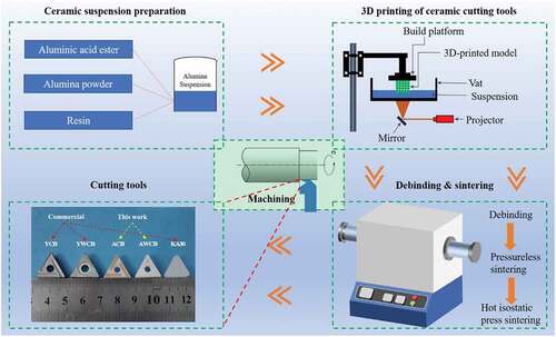
Table 2. Mechanical properties of the cutting inserts.
4.2. Cutting performance and wear mechanisms at different cutting speeds
Among the three cutting parameters, cutting speed vc has the largest effect on the cutting life of the inserts. Thus, the effect of the cutting speed on the cutting performance and wear mechanism was first studied with the constant feed rate and cutting depth of 0.2 mm/r and 0.5 mm, respectively.
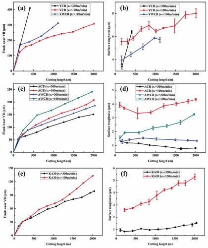
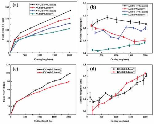
The curves of the flank wear and surface roughness of the workpiece with the cutting length under different cutting speeds are shown in . For all tools, the flank wear increased with increasing cutting length at different cutting speeds, as shown in , c, e). In particular, the flank wear of YWCB was 313 μm at a cutting length of 1100 m, which reached the tool failure standard. When the cutting length was 2000 m, the flank wear of YCB and ACB were approximately 308 and 208 μm, respectively. Hence, the flank wear of YCB was 32% higher than that of ACB. For cutting tools without chip-breaking grooves, the flank wear of YWCB exceeded 300 μm, which is approximately 74% and 264% higher than that of AWCB and KA30 at the same cutting length, respectively. For the ceramic tools, the flank wear of AWCB and KA30 were approximately 241 and 133 μm, respectively, at a cutting length of 2000 m. When the cutting speed was increased to 300 m/min, the flank wear of YCB was approximately 410 μm at a cutting length of 412 m, which is approximately 1600 m less than that at lower cutting speeds (100 m/min). Compared to the lower cutting speeds at the same cutting length, the flank wear of ACB, AWCB, and KA30 were 151, 186, and 99 μm at 300 m/min, which were 27%, 23%, and 26% lower, respectively.
Figure 2. (a, c, e) the relationship between flank wear amount and cutting length, (b, d, f) the relationship between surface roughness and cutting length.
The flank wear of the cutting tool with a chip-breaking groove was lower than that without a chip-breaking groove under the same cutting length, regardless of the cutting speed. This can be attributed to the following. First, the hardness and high-temperature resistance of cemented carbide tools (YCB and YWCB) are lower than those of the ceramic tools. This increases the temperature of the tool tip as the cutting length increases, which decreases the hardness and weakens the bonding strength between the grains, resulting in a sharp increase in the flank wear [Citation28]. The temperature can then be expressed as follows [Citation29]:
where Cθ is the coefficient of temperature; and xθ,yθ, and zθ correspond to the cutting temperature, feed rate, and cutting depth index, respectively, whereby xθ > yθ > zθ > 0. The cutting speed has the most prominent effect on temperature. When the cutting speed was increased, the cutting temperature rapidly increased. In our study, the cutting performance of the cemented carbide tools (YCB and YWCB) rapidly decreased, reaching the tool wear failure standard with an extremely high wear rate. However, for the ceramic cutting tools, increasing the cutting speed reduced the friction and deformation coefficients, and increased the shear angle, thereby decreasing the cutting force. Simultaneously, the increase in the cutting temperature at a high speed reduced the strength and hardness of the workpiece, which could further reduce the cutting force. Therefore, the cutting performance of the ceramic tool at 300 m/min was better than that at 100 m/min. Another reason for the lower flank wear with a chip-breaking groove is the improved chip removal, which reduced the temperature of the tool tip and cutting force, thereby improving the life of the cutting inserts with chip-breaking grooves.
The surface roughness of the workpiece increased with the cutting length, as shown in , d, f). At the cutting speed of 100 m/min, the surface roughness values of the workpiece cut by YCB, YWCB, ACB, AWCB, and KA30 were 5.54–8.02, 3.93–5.88, 3.32–4.33, 1.53–3.26, and 2.59–5.30 μm, respectively. When the cutting speed was increased to 300 m/min, the surface roughness values of the workpiece cut by YCB, YWCB, ACB, AWCB, and KA30 were 3.39–6.40, 0.81–1.29, 1.28–1.55, and 0.83–1.54 μm, respectively. Evidently, the surface roughness of the workpiece cut at a higher speed was larger than that cut at a lower cutting speed because of the decreased chip buildup, cutting force, flank boundary wear, machine tool vibration, and workpiece deformation. In addition, the surface roughness of the workpiece cut using the ceramic tools was lower than that of the cement carbide because of the higher thermal conductivity and affinity with iron of the cemented carbide, thereby easily generating chip accumulation and increasing its cutting temperature.
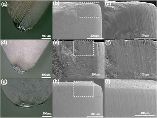
shows the wear morphology of the rake and flank face of the different cutting tools when the cutting speed was 100 m/min. Crescent wear occurred in the rake face of all tools, as shown in , d, g, j, m). The flank face of YCB and YWCB exhibited adhesive wear and cracks, with larger cracks in YWCB, as shown in , e). This is attributed to the cemented carbide, which is not resistant to high temperatures, thereby easily causing cracks when subjected to thermal shock or local temperature rise. Compared to YCB, the chip removal of YWCB was lower, and the tool tip temperature and local temperature difference were higher, resulting in more obvious cracks. For the ceramic tools, the flank wear mainly includes abrasive wear, adhesion wear, and micro chipping, as shown in , k, n), which are related to the properties of alumina ceramics. Owing to the high hardness, good wear resistance, and low toughness of alumina ceramics, chipping can be easily produced with a large cutting force, which reduces the cutting life.
Figure 3. The wear morphology of rake and flank face of different cutting tools when the cutting speed is 100 m/min, (a) the rake face of YCB, (b) the flank face of YCB, (c) magnified image of the rectangle area in b, (d) the rake face of YWCB, (e) the flank face of YWCB, (f) magnified image of the rectangle area in e, (g) the rake face of ACB, (h) the flank face of ACB, (i) magnified image of the rectangle area in h, (j) the rake face of AWCB, (k) the flank face of AWCB, (l) magnified image of the rectangle area in k, (m) the rake face of KA30, (n) the flank face of KA30, (o) magnified image of the rectangle area in n.
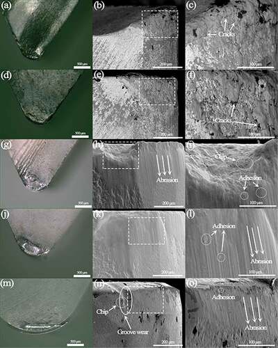
When the cutting speed was increased to 300 m/min, more serious crescent wear and collapse occurred on the rake face of YCB, whereas a large adhesive layer was observed in the plastic deformation area of its flank face, as shown in . This is attributed to the sharp increase in the cutting temperature, and decrease in the hardness and strength of YCB, resulting in plastic flow and peeling of the flank and rake face surfaces. Moreover, the adhesive layer of the tool tip was deformed, resulting in a large plastic deformation, and the rake and flank faces of the tool collapsed with notches. For the ceramic tools, the wear morphology of the flank face was similar to that with the low-speed cutting, which includes abrasive wear, adhesion wear, and micro chipping. In particular, tipping and built-up edge emerged on the AWCB cutting insert because the chips in contact with the rake face of AWCB formed a retention layer through friction. For ACB, the chip-breaking groove can decrease the temperature of the tool tip, flank wear, and cutting force during turning, thereby inhibiting the formation of the built-up edge and collapse. Compared with ACB and AWCB, KA30 is a commercial tool with a higher strength and toughness, and a primary land. Thus, the cutting edge was less likely to collapse and was well preserved under the same cutting conditions.
Figure 4. The wear morphology of rake and flank face of different cutting tools when the cutting speed is 300 m/min, (a) the rake face of YCB, (b) the flank face of YCB, (c) magnified image of the rectangle area in b, (d) the rake face of YWCB, (e) the flank face of YWCB, (f) magnified image of the rectangle area in e, (g) the rake face of ACB, (h) the flank face of ACB, (i) magnified image of the rectangle area in h, (j) the rake face of AWCB, (k) the flank face of AWCB, (l) magnified image of the rectangle area in k.
4.3. Cutting performance and wear mechanisms at different feed rates
The feed rate is another important parameter in the cutting process. The cutting performance and wear mechanism under different feed rates (0.2 and 0.1 mm/r) were investigated with the cutting speed of 300 m/min and cutting depth of 0.5 mm.
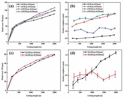
shows the flank wear and surface roughness of the workpiece with the cutting length under different feed rates. The flank wear increased with the feed rate (, c)). When the feed rate was 0.1 mm/r, the flank wear values of ACB, AWCB, and KA30 were 106, 130, and 79 μm at the cutting length of 2000 m. Compared with the feed rate of 0.2 mm/r, the flank wear values of ACB, AWCB, and KA30 were lower by 30%, 30%, and 20%, respectively. This result can be depicted according to the cutting force equation [Citation29]:
Figure 5. The relationship between flank area and the cutting length at different feed rates, (a) ACB(AWCB), (c) KA30, The relationship between surface roughness and the cutting length at different feed rates, (b) ACB(AWCB), (d) KA30.
where Fz,Fy, and Fx are the main cutting, back, and feed force, respectively; CFz,CFy, and CFx are the coefficients; XFz,YFz, and nFz are the indices of the back draft, feed rate, and cutting speed, respectively; and KFz,KFy, and KFx are the correction indices for each cutting component. Generally, XFz > 0, YFz > 0, and nFz < 0. When f increases, the cutting force, cutting temperature, and tool wear increase, resulting in a reduced cutting life.
The curves of the surface roughness of the workpiece are shown in , d). When the feed rate was 0.1 mm/r, the surface roughness values of the workpiece cut by ACB, AWCB, and KA30 were 0.46–0.75, 0.86–1.24, and 0.61–1.57 μm at the cutting length of 2000 m, respectively. This indicates that reducing the feed rate can improve machining quality. Furthermore, ACB obtained the best machine quality with the maximum surface roughness of 0.75 μm, which was lower than that of AWCB and KA30. These results are related to the residual area, expressed as [Citation29]:
where Rmax is the residual area, f is the feed rate, and r is the tool tip radius. Therefore, if f decreases, Rmax decreases, thereby suppressing the generation of chip deposits and scales. This in turn reduces the feed rate can improve the processing quality.
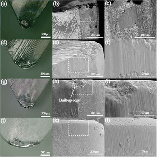
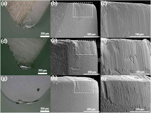
shows the wear morphology of the rake and flank face of the different cutting tools with the feed rate of 0.1 mm/r. The wear degree of the rake face of the cutting inserts was clearly smaller than that with the feed rate of 0.2 mm/r. In addition, the cutting force and temperature of the tools decreased, resulting in a complete cutting edge. The rake face of KA30 had the lowest wear. The AWCB rake face was partially peeled off, as shown in , d, g). In addition, abrasive wear occurred on the flank face of the tools, as shown in (b, e, h). Adhesive wear was obvious on the flank face of AWCB ( (f)), whereas it was rarely observed on ACB ()). These results are related to the chip-breaking groove of ACB, which can reduce cutting force and tool tip temperature.
Figure 6. The wear morphology of rake and flank face of different cutting tools when f is 0.1 m/r, (a) the rake face of ACB, (b) the flank face of ACB, (c) magnified image of the rectangle area in b, (d) the rake face of AWCB, (e) the flank face of AWCB, (f) magnified image of the rectangle area in e, (g) the rake face of KA30, (h) the flank face of KA30, (i), magnified image of the rectangle area in h.
4.4. Cutting performance and wear mechanisms at different cutting depth
To study the effect of the cutting depth on the cutting performance and wear mechanism, two cutting depths (0.25 and 0.5 mm) were used in this study with the cutting speed of 300 m/min and feed rate of 0.1 mm/r. The effect of the cutting depth on the flank wear of different tools is illustrated in ) and (c). When the cutting depth was 0.25 mm, the flank wear values of ACB, AWCB, and KA30 were 119, 120, and 80 μm, respectively, at a cutting length of 2000 m. Compared with the cutting depth of 0.5 mm, a minimal difference was observed in the flank wear of the tools. In particular, for ACB and AWCB, the flank wear was similar to that at the cutting depth of 0.25 mm. In contrast, the flank wear of AWCB was 22.6% higher than that of ACB at a cutting depth of 0.5 mm. The surface roughness of the workpiece cut by ACB was lower than that of AWCB. The surface roughness of the workpiece at the cutting depth of 0.25 mm was higher than that at 0.5 mm, as shown in , d). These results are related to the chip-breaking groove, which can reduce the cutting force and guide the chip.
Figure 7. Relationship between the flank wear and cutting length at different cutting depths: (a) ACB and AWCB, and (c) KA30. Relationship between the surface roughness and cutting length at different cutting depths: (b) ACB and AWCB, and (d) KA30.
shows the wear morphology of the rake and flank face of the tools with different cutting depths. The wear of the rake face of all tools at the cutting depth of 0.25 mm was less than that at the cutting depth of 0.5 mm, as shown in , d, g). From the flank face of the tools, the main wear mechanisms were abrasive and adhesive wear. Moreover, blade collapse did not occur.
Figure 8. Wear morphology of the rake and flank faces of different cutting tools when ap = 0.25 mm: (a) rake face and (b) flank face of ACB with the (c) magnified image of the rectangle area in b; (d) rake face and (e) flank face of AWCB with the (f) magnified image of the rectangle area in e; and (g) rake face and (h) flank face of KA30 with the (i) magnified image of the rectangle area in h.
5. Conclusion
In this study, due to that commercial ceramic cutting tools do not contain grooves because of the processsing difficulty, vat-photopolymerization-based 3D printing was adopted to fabricate Al2O3 ceramic cutting tools with grooves and the cutting performance of cutting tool was tested for the first time. The effects of the cutting speed, feed rate, and cutting depth on the flank wear and surface roughness of the workpiece were systematically investigated. The wear mechanisms of the tools were thoroughly studied. The main conclusions of this study are as follows:
(1) High-performance alumina cutting inserts were successfully prepared by VPP and pressureless sintering, followed by hot isostatic press sintering. The relative density, Vickers hardness, bending strength, and fracture toughness of the inserts were 99.34%, 18.3 GPa, 513 MPa, and 3.5 MPa·m1/2, respectively.
(2) The cutting speed, feed rate, and cutting depth all influence the flank wear and surface roughness of the workpiece, and cutting speed has the greatest impact.
(3) During continuous dry turning, different tools had different wear mechanisms. The main wear mechanisms of the cement carbide tools were adhesive wear and breakage, whereas that of the alumina ceramic cutting tools were abrasive and adhesive wear.
(4) For the as-prepared alumina ceramic cutting inserts with and without chip breaker grooves, the cutting performance of the alumina ceramic cutting inserts with chip breaker grooves was much better than that without chip breaker grooves.
Abbreviations
VPP, vat photopolymerization.
Acknowledgments
This work was financially supported by Local Innovative and Research Team Project of Guangdong Pearl River Talents Program (Grant No. 2017BT01C169), National Natural Science Foundation of China (NSFC, Grant No. 91960102), Guangdong Provincial Science Fund for Distinguished Young Scholars (2020B1515020059), and National Natural Science Foundation of China (NSFC, Grant No. 51872052).
Disclosure statement
The authors do not have any conflicts of interest to declare.
Additional information
Funding
References
- Wu H, Liu W, He R, et al. Fabrication of dense zirconia-toughened alumina ceramics through a stereolithography-based additive manufacturing. Ceram Int. 2017;43:968–972.
- Schwentenwein M, Homa J. Additive manufacturing of dense alumina ceramics. Int J Appl Ceram Tech. 2015;12:1–7.
- Carloni D, Zhang G, Wu Y. Transparent alumina ceramics fabricated by 3D printing and vacuum sintering. J Eur Ceram Soc. 2021;41:781–791.
- Zhou M, Liu W, Wu H, et al. Preparation of a defect-free alumina cutting tool via additive manufacturing based on stereolithography - Optimization of the drying and debinding processes. Ceram Int. 2016;42:11598–11602.
- Mamatha S, Biswas P, Ramavath P, et al. 3D printing of complex shaped alumina parts. Ceram Int. 2018;44:19278–19281.
- Mamatha S, Biswas P, Ramavath P, et al. Effect of parameters on 3D printing of alumina ceramics and evaluation of properties of sintered parts. J Asian Ceram Soc. 2021;9:858–864.
- Mohanty S, Rameshbabu A, Mandal S, et al. Critical issues in near net shape forming via green machining of ceramics: a case study of alumina dental crown. J Asian Ceram Soc. 2013;1:274–281.
- Wu H, Liu W, Lin L, et al. Realization of complex-shaped and high-performance alumina ceramic cutting tools via Vat photopolymerization based 3D printing: a novel surface modification strategy through coupling agents aluminic acid ester and silane coupling agent. J Eur Ceram Soc. 2023;43:1051–1063.
- Lee H, Lee H, Kim K, et al. A Study on the Mechanical Properties of Al2O3 Cutting Tools by DLP-based 3D Printing. J Powder Mater. 2019;26:508–514.
- Chen Z, Li Z, Li J, et al. 3D printing of ceramics: a review. J Eur Ceram Soc. 2019;39:661–687.
- Song X, Chen Y, Lee T, et al. Ceramic fabrication using Mask-Image-Projection-based Stereolithography integrated with tape-casting. J Manuf Process. 2015;20:456–464.
- Zhang K, Xie C, Wang G, et al. High solid loading, low viscosity photosensitive Al2O3 slurry for stereolithography based additive manufacturing. Ceram Int. 2019;45:203–208.
- Liu X, Zou B, Xing H, et al. The preparation of ZrO2-Al2O3 composite ceramic by SLA-3D printing and sintering processing. Ceram Int. 2020;46:937–944.
- Zheng T, Wang W, Sun J, et al. Development and evaluation of Al2O3–ZrO2 composite processed by digital light 3D printing. Ceram Int. 2020;46:8682–8688.
- Xing Z, Zhou H, Liu W, et al. Efficient cleaning of ceramic green bodies with complex architectures fabricated by stereolithography-based additive manufacturing via high viscoelastic paste. Addit Manuf. 2022;55:102809.
- Lin L, Wu H, Ni P, et al. Additive manufacturing of complex-shaped and high-performance aluminum nitride-based components for thermal management. Addit Manuf. 2022;52:102671.
- Liu Y, Zhan L, Wen L, et al. Effects of particle size and color on photocuring performance of Si3N4 ceramic slurry by stereolithography. J Eur Ceram Soc. 2021;41:2386–2394.
- He R, Zhou N, Zhang K, et al. Progress and challenges towards additive manufacturing of SiC ceramic. J Adv Ceram. 2021;10:637–674.
- Zhang K, He R, Ding G, et al. Effects of fine grains and sintering additives on stereolithography additive manufactured Al2O3 ceramic. J Eur Ceram Soc. 2021;47:2303–2310.
- Li Y, Wang M, Wu H, et al. Cure behavior of colorful ZrO2 suspensions during Digital light processing (DLP) based stereolithography process. J Eur Ceram Soc. 2019;39:4921–4927.
- Xing H, Zou B, Lai Q, et al. Preparation and characterization of UV curable Al2O3 suspensions applying for stereolithography 3D printing ceramic microcomponent. Powder Technol. 2018;338:153–161.
- Lutov V. Selecting the optimum size of chip-breaking grooves. Mach Tool. 1962;33:27–30.
- Sisoev V. Fundamentals of Metal Cutting and Cutting Tools. Moscow: Mashgiz; 1962.
- Worthington B. The effect of rake face configuration on the curvature of the chip in metal cutting. Int J Mach Tool Manu. 1975;15:223–239.
- Worthington B. The operation and performance of a groove-type chip forming device. Int J Prod Res. 1976;14:529–558.
- EVans A, EA C. Fracture Toughness Determinations By Identation. 1976;59:371–372.
- Xie Z. Structural Ceramics Tsinghua. Beijing: Tsinghua University Press. 2011;19–24.
- Ezugwu E. Key improvements in the machining of difficult-to-cut aerospace superalloys. Int J Mach Tool Manu. 2005;45:1353–1367.
- Wu W, Xin Z. Metal cutting principle and tools. Beijing: National Defense Industry Press. 2009;64–65.