
 ?Mathematical formulae have been encoded as MathML and are displayed in this HTML version using MathJax in order to improve their display. Uncheck the box to turn MathJax off. This feature requires Javascript. Click on a formula to zoom.
ABSTRACT
The train running safety on non-ballasted bridges is studied based on safety indices from the vertical wheel–rail forces. A 2D train–track–bridge interaction model that allows for wheel–rail contact loss is adopted for a comprehensive parametric study on high-speed passenger trains. The relation between bridge response and vehicle response is studied for more than 200 theoretical bridges in 1–3 spans. The bridge’s influence on running safety and passenger comfort is differentiated from the influence of the track irregularities. The Eurocode bridge deck acceleration limit for non-ballasted bridges is 5 m/s2 based on the assumed derailment risk at 1 g from wheel–rail contact loss. This study shows that the running safety indices are not compromised for bridge accelerations up to 30 m/s2. Thus, accelerations at 1 g do not in itself lead to contact loss and there is potential to enhance the Eurocode safety limits for non-ballasted bridges.
1. Introduction
Train running safety is generally assessed based on the lateral and vertical wheel–rail forces. The risk for derailment on bridges has been investigated using three-dimensional (3D) train–track–bridge interaction models with advanced wheel–rail contact models [Citation1–Citation8]. The objective has often been to study running safety under crosswind loads, earthquake and lateral bridge dynamics; Arvidsson and Karoumi [Citation9] provide further references. Two-dimensional (2D) approaches have also been adopted [Citation10,Citation11] where the running safety is assessed by the vertical wheel–rail unloading.
Several design codes [Citation12,Citation13] impose limits on the wheel unloading and the derailment factor, also involving the lateral wheel–rail force. The running safety is ideally assessed from such indices based on the wheel–rail forces. In the bridge design stage however, this may require unnecessarily complicated models. As an alternative to the safety indices from wheel–rail forces, the Japanese design codes [Citation13] provide deflection limits to ensure running safety. In the Eurocode EN 1990-A2 [Citation14], the running safety is ensured based on limits for the bridge deck vertical acceleration together with limits on displacement and end rotations. The background to the acceleration criterion is the risk for ballast destabilization. Experiments and in-situ measurements have shown that ballast may lose its interlock at accelerations exceeding 0.7 g. A safety factor of 2 led to the stipulated acceleration limit of 3.5 m/s2 for ballasted bridges. Rocha et al. [Citation11] used a probabilistic approach to study the safety for one case study bridge and concluded that 3.5 m/s2 was reached before wheel unloading occurred. The 5 m/s2 limit for non-ballasted bridges is based on the assumed contact loss between the wheel and the rail at the gravitational acceleration 1 g, with a safety factor of 2 [Citation15]. To the authors’ knowledge, this has not been verified by simulations or measurements.
Train–track–bridge interaction models in 2D and 3D are also often adopted to study passenger comfort [Citation1,Citation3,Citation5,Citation16,Citation17]. Passenger comfort is generally assessed from measures related to the car body acceleration. Models accounting for the flexibility of the car body can be used for detailed assessments [Citation18]. Research on the relation between bridge vibration and car body acceleration [Citation16,Citation17] has resulted in bridge deck deflection limits in EN 1990-A2 as an indirect way to ensure ride comfort. The limits aim at a comfort level denoted as ‘very good comfort’ with maximum car body acceleration of 1 m/s2 due to bridge vibration. The maximum relative deflection are given for simply supported bridges in three or more spans and have multiplication factors that allow for higher deflection for single and two span bridges, as well as continuous bridges in three or more spans.
The aim of this work is to study the train running safety and passenger comfort on non-ballasted bridges. The running safety is assessed from safety indices based on the vertical wheel–rail force. The novelty of the work lies in the comprehensive parametric study in which the running safety and passenger comfort are put in relation to the vertical bridge response (deck acceleration and deflection). The wheel–rail force is studied for bridges at the design limit for acceleration and deflection. The effect of track irregularities on the wheel–rail force is shown to be large and a measure to isolate the effect of the bridge dynamics is needed. Therefore, comparisons are made between simulations at a track section with and without bridge. A 2D coupled train–track–bridge interaction model is adopted with a Hertzian contact model that allows for wheel–rail contact loss. The car body acceleration in the rigid multi-body vehicle model is used to estimate the passenger comfort, neglecting the car body flexibility and the passenger seat dynamic properties. The 2D model allows the analysis of thousands of train passages at a relatively low computational cost. Not often seen in the literature, this paper presents results from more than 200 bridges and over 200 000 train passage analyses. As a consequence of the 2D model, the lateral dynamics are neglected. The 2D analysis is motivated by the assumption that the vertical bridge vibration will primarily affect the vertical vehicle response. The study is a continuation of the work presented by Arvidsson and Andersson [Citation19].
2. Running safety
Loss of contact may occur for high dynamic wheel loads, which under certain conditions can lead to derailment. Flange climbing occurs if the vertical force is not large enough to prevent the wheel from climbing onto the top of the railhead. The risk for derailment from flange climbing is commonly estimated from the quotient of the lateral, , to the vertical,
, wheel–rail force. Nadal’s equation gives a theoretical limit for the derailment factor [Citation20]:
for contact angle and friction coefficient
. The EN 14363 [21] limit for the
ratio is 0.8 for signals low-pass filtered at 20 Hz and with a sliding mean with 2.0 m window length. The filtering and sliding mean of the signal is in line with field tests and simulations showing that derailment from flange climbing only occurs when the limit has been exceeded for a certain distance or time duration [Citation4,Citation7,Citation22]. The relative wheel–rail displacement needs to overcome the flange height, typically 30 mm, in order for the wheel to derail. The Japanese National Railways (JNR) allows for an exceedance of the
safety limit for time periods shorter than 50 ms [Citation22], while Ishida et al. [Citation7] suggest 15 ms. Montenegro [Citation4] concludes that the time limit 15 ms is conservative as the relative wheel–rail displacement is small compared to the flange height during such a short time.
Loss of contact occurs if the wheel unloading ratio (or offload factor) equals 1 [Citation21]:
where is the static vertical wheel load and
is the minimum dynamic vertical wheel load. Given a certain duration and the presence of a lateral force, the contact loss could pose a risk for derailment. The wheel unloading ratio is used together with the derailment factor in the Chinese and Japanese bridge design codes [Citation12,Citation13]. The Japanese standards limit the wheel unloading to 0.8 for normal track maintenance profiles and to 0.37 for analyses with smooth track. The European standards for railway vehicles limit the wheel unloading to 0.6 for the quasi-static wheel forces in EN 14363 [Citation21], while EN 14067 [Citation23] applies the limit 0.9 related to cross wind loading.
In the European bridge design codes, the EN 1990-A2 limit on vertical deck acceleration is related to running safety. Therefore, the relation between vertical bridge response and running safety is studied in this paper. The problem is studied in 2D using the assumption that the vertical bridge vibration will primarily affect the vertical vehicle response. Two limits for running safety are adopted based on the vertical wheel–rail force: (1) filtered wheel unloading , and (2) unfiltered wheel unloading with a duration of contact loss
15 ms. For the first safety limit, the wheel unloading is calculated from wheel–rail forces filtered at 20 Hz, in line with the filtering in EN 14363. This mitigates the contact losses originating from higher oscillation frequencies. The wheel rise is small during short-time wheel unloading [Citation4,Citation7,Citation19] which is why the high oscillation frequencies are not relevant for derailment, as discussed also in [Citation24]. The limit for duration of contact loss is chosen in line with the time limit for flange climbing suggested by [Citation7].
3. Model
The 2D finite element (FE) model of the train–track–bridge system is depicted in . The non-ballasted track model is an idealization of a track system with discrete rail fastenings incorporated in a concrete track slab [Citation8,Citation25,Citation26]. The rail and the track slab are modelled by Euler-Bernoulli beams with the rail fastenings and the track slab–subgrade interface modelled by discrete spring–dashpots in parallel. The track slab at the embankment before and after the bridge has an effective stiffness and mass that includes the contribution from the supporting concrete base plate or stabilized soil material. At the bridge, the track slab is separated from the deck by means of a mortar bed modelled as a stiff spring–dashpot layer. The track slab is discontinuous at the bridge ends. The bridge is modelled as one continuous or a sequence of simply supported Euler-Bernoulli beams on fixed supports in 1–3 spans. The beams in the rail, track slab and bridge are divided into elements of equal length, corresponding to three elements per fastening spacing.
Figure 1. 2D train–track–bridge coupled model.
The train is modelled as a rigid multi-body system including the car body (2 DOF), the bogie (2 DOF) and the wheel (1 DOF). The primary and secondary suspension systems are represented by spring–dashpots in parallel. For conventional bogie (non-articulated) carriages the interaction between adjacent carriages is neglected. For articulated carriages [Citation27,Citation28], sharing a Jacobs bogie, a stiff vertical coupling between adjacent car bodies is considered; see . The mass, damping and stiffness matrices for the conventional carriages can be found in many sources; see e.g. [Citation26,Citation29]. The vertical coupling between car bodies in the articulated train configuration is represented by coupling terms in the stiffness matrix between the DOF:s (vertical and rotational) of adjacent car bodies.
3.1. Coupled equations of motion
The coupled equations of motion of the train–track–bridge model can be expressed with block matrices:
where the sub-indices V, T and B indicate vehicle, track and bridge subsystems respectively. The main diagonal terms are the FE representation of each subsystem. The coupling of the subsystems is expressed with the off-diagonal terms and additions to the diagonal terms. The coupling between the track and the bridge is composed of the terms from the spring–dashpot layer between the track slab and the bridge. The track–bridge coupling terms remain constant since there is no change in their configuration during one simulation and their addition to the diagonal terms are included in ,
,
and
. The derivation of these block matrices is described by Lou [Citation30]. The vehicle–track coupling is composed of the terms from the wheel–rail contact and depends on the vehicle’s position with time. These terms,
,
and
include the wheel–rail contact stiffness,
, together with the cubic shape function of the 4-DOF beam element evaluated at the contact point with the
th wheelset,
, and need to be recalculated for every time step:
The wheel–rail contact is described with a linearized Hertzian spring that allows for loss of contact. General Hertz contact can be described by the force–deformation (,
) relation:
with the radius of the wheel, , and the radius of the rail,
, both with elastic modulus
and Poisson ratio
. The normal wheel–rail force can be linearly approximated by a stiffness coefficient [Citation31]:
at a given point in the force–deformation relation. In this study, the wheel–rail force is linearized around the static axle load with values for the parameters in Equation (6) according to [Citation31]. When the wheel loses contact with the rail the force is set to zero. Thus, we have the relation:
where is the vertical wheel–rail force depending on the deflection of the wheel,
, the deflection of the rail in contact,
, and the track irregularity
. In each time step, the contact stiffness needs to be updated according to Equation (7). The contact stiffness is initially based on the contact condition from the previous time step (contact or loss of contact). When needed, iterations are performed within each step to update the contact condition.
The external force vector in Equation (3) includes the gravitational load on the vehicle. The track irregularities are treated as an additional external force [Citation30],
, added to the wheel nodes and, by means of the element shape functions, to the rail nodes in contact. The model is a further development of the rigid contact train–track–bridge model presented by Cantero, Arvidsson, OBrien and Karoumi [Citation32]. A Newmark direct integration method is used with time step 0.5 ms.
4. Model validation
Wheel–rail forces were measured with strain gauges at an instrumented wheelset in a Regina type train at 220 km/h within the Swedish Green Train project in 2006 [Citation33]. The present model was adjusted to model the train and the ballasted track according to [Citation33,Citation34]. Track irregularities were included based on measurements performed at the test section between Skövde and Töreboda on the main line Stockholm–Gothenburg. As is shown in , the present model is in good agreement with the measured results, both in amplitude distribution and for the peaks occurring at isolated track defects.
Figure 2. The present model validated against measured wheel–rail forces (mean value from the left and right wheel) from the Green Train project: (a) power spectral density and (b) normal probability distribution for the dynamic wheel–rail force (Qdyn) at a 2000 m track section, and (c) 60 m sample. Data from Li et al. [Citation33].
![Figure 2. The present model validated against measured wheel–rail forces (mean value from the left and right wheel) from the Green Train project: (a) power spectral density and (b) normal probability distribution for the dynamic wheel–rail force (Qdyn) at a 2000 m track section, and (c) 60 m sample. Data from Li et al. [Citation33].](/cms/asset/11c0ffd7-8ffc-43e2-9507-27cd5771ebde/tjrt_a_1503975_f0002_oc.jpg)
presents a validation of the present 2D model against the 3D train–track interaction model developed by Zhai et al. [Citation1]. The 3D model includes a rigid multi-body vehicle model with 35 DOFs; the non-linear Hertz contact theory is used together with a modified Kalker’s linear creep theory for the wheel–rail contact. A single high-speed passenger carriage was simulated running over a ballasted track section with random track irregularities in both vertical and lateral directions at a speed of 160 km/h. The ballasted track was modelled in three levels (rail, sleeper and ballast connected by spring–dashpots) with properties according to [Citation35]. The vertical result components are compared to the present 2D model results in (a) and (b). Very good agreement is seen for the wheel–rail force, even though the 2D model does not include the additional contribution from the lateral dynamics. The vertical car body acceleration is almost identical for the two models. In the 3D model, the lateral wheel–rail force and car body acceleration (not shown in the figure) have an amplitude of around 10 kN and 0.5 m/s2, respectively.
Figure 3. The present model validated against the 3D model in [Citation1]: (a) vertical dynamic wheel–rail force (Qdyn, 1st wheelset) and (b) car body acceleration (ac). The 3D wheel–rail force is the mean value from the left and right wheel.
![Figure 3. The present model validated against the 3D model in [Citation1]: (a) vertical dynamic wheel–rail force (Qdyn, 1st wheelset) and (b) car body acceleration (ac). The 3D wheel–rail force is the mean value from the left and right wheel.](/cms/asset/35a387b9-fe37-490b-845e-43f937f28269/tjrt_a_1503975_f0003_oc.jpg)
5. Parametric study input and analysis procedure
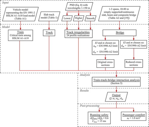
The analysis procedure for the parametric study is illustrated in . In the post-processing of the results, the train running safety and passenger comfort are estimated from comparison against the limit values and put in relation to the bridge deck vertical response. The train, track and track irregularity data are according to Sections 5.1 and 5.2 with a sensitivity study in Section 5.3. The bridges cross-sectional data, according to Section 5.4, are chosen so as to reach the EN 1990-A2 limit for acceleration or deflection. All bridges are in that sense dynamically sensitive.
Figure 4. Parametric study analysis procedure.
5.1. Train
A vehicle model representing the EN 1991–2 [Citation36] high speed load model A (HSLM-A) was established according to in the Appendix. The HSLM-A is a moving load model with axle distances according to articulated trains without specified suspension or vehicle body data. The vehicle mechanical data was therefore assumed based on articulated train properties from [Citation37] and was adjusted to fit each of the 10 HSLM trains (A1–A10). The car body mass was adjusted to give the specified axle load for each train, 17–21 tonne/axle. The primary and secondary suspension stiffness were adjusted to give realistic bogie and car body bounce frequencies, 5 Hz and 0.7 Hz, respectively. The wheelset mass was assumed as a relevant upper limit (2000 kg). All axle distances were chosen according to EN 1991–2; for more details, see [Citation19].
5.2. Track and track profile quality
The slab track properties are given in . The stiffness of the elastic components in the rail fastening was chosen as 22.5 MN/m per rail [Citation25,Citation38], with a 10% damping ratio. The bed modulus for subgrade/mortar given in was assumed, and was multiplied with the slab width, , (effective width 3.2 m at embankment and slab width 2.4 m at bridge) to obtain the 2D spring stiffness per meter track.
Table 1. Slab track model properties (two rails) with symbols from .
Random track irregularities were included based on the theoretical German power spectral density (PSD) function m
/(rad/m):
for wavelengths rad/m,
= 0.0206 rad/m,
= 0.8246 rad/m and track quality factor
rad
m [Citation39]. The profile was scaled to a specific track quality by adjusting
. Spatial samples were extracted from the PSD functions by means of the inverse Fourier transform with random phases assigned to each harmonic component.
Wavelengths 1–150 m were included in the analysis where the lower range is more relevant for running safety and the upper range is more relevant for passenger comfort [Citation32,Citation40]. This includes EN 13848–5 [Citation40] ranges D1 (3–25 m), D2 (25–70 m) and D3 (70–150 m), but also wavelengths down to 1 m according to Swedish standards [Citation41].
Two track quality levels were considered according to the EN 13848–5 limits for isolated defects and the EN 13848–6 [Citation42] ranges for standard deviation in D1 (). For the lower track quality, each random track profile sample including wavelengths 1–150 m was scaled with track quality factor
. This corresponds to a standard deviation in D1 of
mm. The maximum zero to peak values for the lower track quality are close to the EN 13848–5 alert limit for speeds 300–360 km/h. Thus, wheel unloading can be assessed close to the alert limit. A higher track quality level was also considered with standard deviation
mm (
). The higher track quality corresponds to a well-maintained track for high speeds and is similar to the Chinese PSD for non-ballasted tracks [Citation8].
For each quality level, 24 track irregularity samples were considered. Each sample was acquired as the one with the maximum peak amplitude out of 1000 random samples. The point with maximum deviation was placed at the mid span of the bridge. For two span bridges it was placed at the first span, while in the middle span for three span bridges. A minimum of 150 m approach track was considered in order for the vehicle to reach a reasonable stable level of vibration from the random track irregularities.
5.3. Sensitivity analysis: train and track
A sensitivity analysis for the train and track parameters was performed for the HSLM-A1 train travelling a 400 m track section without bridge. The maximum response from the speed range 260–400 km/h was extracted for 2000 Monte Carlo samples with variations in the model input parameters following uniform distributions. The mean values for the train parameters follow in the Appendix. Variation was introduced in all mechanical data (% in mass and inertia, and
% in suspension characteristics). The variation of train characteristics for a specific train type can be much smaller [Citation43] because of high manufacturing accuracy. However, since the HSLM-A trains represent an envelope of passenger trains, the variations were chosen to represent a reasonably realistic variation between different trains. Similar levels of variation are used in [Citation11]. The mean values of the track parameters are according to with a variation in the rail fastening stiffness (40–160 MN/m, two fastenings) covering a wide range of track stiffness. The rail fastening damping was varied 7–13%. Track irregularities with wavelengths 1–150 m were included in the analyses. Instead of the two discrete levels of track irregularities according to Section 5.2, the track profile (one realization) was here randomly scaled to a resulting standard deviation
between 0 and 1 mm in each Monte Carlo sample.
The Monte Carlo sample results are plotted against the standard deviation of track irregularities in . The filtered wheel unloading, contact loss and car body acceleration are all sensitive to the track quality level and increase with increasing track irregularities. The remaining scatter is due to the variation in rail fastening and vehicle mechanical data. Colour scales show the influence of the second most important parameter (after track irregularities) for each output.
Figure 5. Results from 2000 Monte Carlo samples with random vehicle and track data plotted against the track profile standard deviation (σ3−25) for (a) filtered wheel unloading (∆Q20Hz/Q0), (b) contact loss (Closs) and (c) car body acceleration (ac).
A significant part of the scatter in the wheel unloading can be explained by the variation in wheel mass with higher unloading for higher wheel masses. This is visualized in ) by a colour scale based on the wheel mass. However, the variation in the wheel unloading is fairly small in relation to the limit value (0.6). This indicates that the running safety index for filtered wheel unloading is relatively insensitive to variation in vehicle and rail fastening input parameters. The colour scale in ) shows that the scatter in the contact loss cannot be clearly explained by the variation in wheel mass. The main reason is that the axle load (car body mass) also has an important effect where the contact loss tends to be longer for lower axle loads.
The colour scale in ) shows the influence of the secondary suspension stiffness on the car body acceleration. The remaining scatter indicates that the other parameters also have considerable influence. The scatter is considerable in relation to the limit value (1.0 m/s2) indicating that solid conclusions on the passenger comfort would require vehicle mechanical data that represent an envelope of real trains.
5.4. Bridges
The parametric study covers single-track bridges in 1–3 spans of lengths 10–80 m. Both simply supported and continuous spans were considered for the 2 and 3 span bridges. The bridge deck damping ratios were chosen according to EN 1991–2. The cross-sections for concrete slab bridges, steel–concrete composite bridges and concrete beam bridges were chosen according to [Citation19]. Two sets of bridges were studied:
(1) original sections
(2) reduced sections.
For the original sections, each bridge was optimized to fulfil the EN 1990-A2 [Citation14] limit for acceleration or deflection. The cross-sections have not been checked for static loading. The purpose was primarily to obtain bridges at the design limit for dynamic loading with reasonably realistic cross-sections. The shorter spans (up to 30–50 m) were limited by the acceleration criterion while the longer spans were limited by the deflection criterion.
As discussed in Section 1, the acceleration limit is related to running safety while the deflection limit is related to passenger comfort. As the physical background to the acceleration limit is vague, the second set of bridges was chosen to reach the EN 1990-A2 limit for deflection, disregarding the acceleration limit. This results in a reduced stiffness for the short and medium span bridges. For some of these bridges the reduction is up to 60–80% and they are significantly weaker than most existing bridges. This implies that these cross-sections would instead be governed by the static design. The cross-sectional properties for simply supported bridges in 1–3 spans are given in in the Appendix; for the continuous bridges see [Citation19].
To differentiate between the bridge’s influence on the running safety and the influence of the irregular track profile, simulations were performed for a track section with and without the bridge. To make direct comparison possible, the same track profile was used for both cases. All vehicle results were extracted from the time period corresponding to when the first wheel in the carriage reaches the bridge until the last wheel in the carriage has travelled one carriage length away from the bridge. The vehicle response from the track section with no bridge was extracted from the corresponding time period to the case with the bridge.
6. Results
In this section, the results for the two sets of bridges are discussed: (1) original sections chosen to reach the EN 1990-A2 limit for acceleration or deflection and (2) reduced sections chosen to reach the limit for deflection, disregarding the acceleration limit. The presented bridge deck acceleration and deflection are filtered at 20 Hz, in line with the filtered wheel–rail force. The car body acceleration (maximum from the centre and ends of the carriage) and wheel–rail force are shown for the most critical carriage in the HSLM-A train.
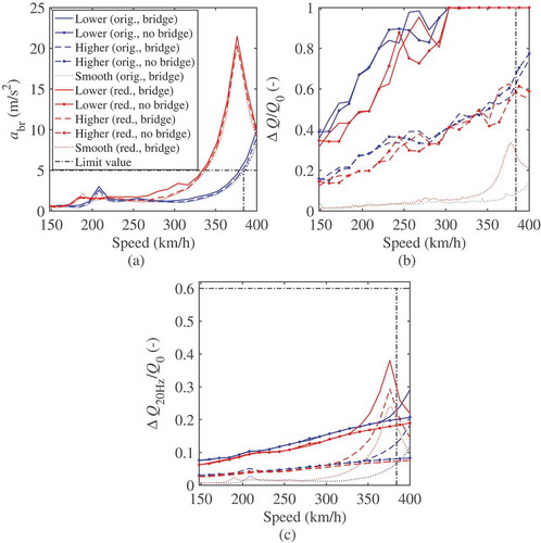
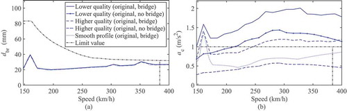
To illustrate some of the more important results, shows an example of bridge acceleration and wheel unloading against speed. Results are shown for the 20 m, single span, beam bridge. The wheel unloading is also shown for a reference track section without the bridge. The bridge acceleration for the original section reach the acceleration limit 5 m/s2 at the most critical speed, and is above 20 m/s2 for the reduced section. The influence of the track quality on the wheel unloading is clearly seen with increasing unloading at lower track quality. The wheel unloading increases with speed due to the increasing excitation from the wheel running over the irregular track. For the original cross-section, a very slight additional filtered wheel unloading is observed at the most critical speed compared to the track section without bridge; a larger addition is seen for the reduced cross-section.
Figure 6. Maximum bridge and vehicle results from 24 profile realizations for the 20 m single span beam bridge (HSLM-A1 for the original section and HSLM-A2 for the reduced section): (a) bridge acceleration (), (b) unfiltered and (c) filtered wheel unloading (
,
).
shows an example of bridge deflection and car body acceleration against speed for the 50 m, single span, beam bridge. A peak is seen at 160 km/h where the car body acceleration exceeds the comfort limit 1 m/s2, even for the smooth track profile. This peak corresponds to a resonance peak in the bridge deflection at a point where the deflection criterion is relaxed due to low speed. At this peak, the bridge vibration governs the car body acceleration and the additional excitation from the track irregularities has very little effect. Away from the peak, on the other hand, the addition from the irregular track profile is significant.
Figure 7. Maximum bridge and vehicle results from 24 profile realizations for the 50 m single span beam bridge (original cross-section, HSLM-A10): (a) bridge deflection () and (b) car body acceleration (
).
The maximum bridge and vehicle results as a function of span length are shown in as envelopes including all bridges in the study. The design speed is 320 km/h; for each bridge, the maximum response for the most critical HSLM-A train with a speed km/h and 24 track profile realizations is included. The acceleration and displacement levels are similar for both the smooth track profile and the two levels of irregular profile as much of the high-frequency content from the wheels running over the irregular track is removed by the 20 Hz low-pass filter. No major differences in bridge or vehicle results can be observed between the simply supported bridges and the continuous bridges from the dashed and continuous lines indicating maximum response for each bridge type.
Figure 8. Envelope of maximum bridge and vehicle results for slab, beam and composite bridges in 1–3 spans: (a)–(b) bridge acceleration (), (c)–(d) bridge deflection (
), (e)–(f) wheel unloading (
), (g)–(h) filtered wheel unloading (
), (i)–(j) contact loss (
) and (k)–(l) car body acceleration (
). Maximum results for simply supported and continuous bridges in 2–3 spans are indicated with dashed and continuous lines, respectively.
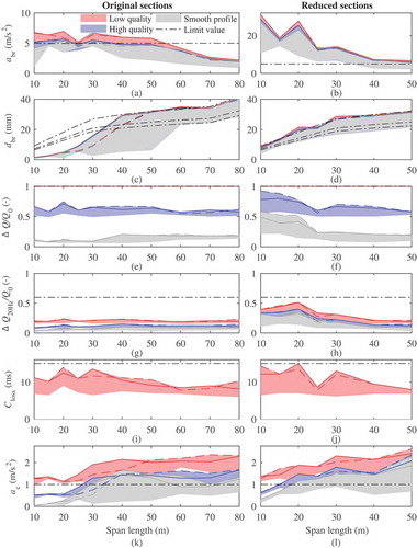
The following observations on running safety and passenger comfort are common for both the original and the reduced cross-sections:
– The track quality has a large influence on the wheel–rail forces with no loss of contact for the smooth and the higher quality profile; see (e–f), (i–j). For the lowerquality profile, contact loss occurs.
– The running safety index for contact loss (15 ms) and filtered wheel unloading (0.6) are not compromised for any of the bridges; see (g–j).
– The track quality has a large influence also on the car body acceleration; see (k–l).
The relation between the bridge response and the running safety and comfort is discussed for the original and the reduced sections in Section 6.1 and 6.2, respectively.
6.1. Original cross-sections
For the original cross-sections, the bridge deck acceleration limit (5 m/s2) is reached for spans up to 30–50 m while the deflection limit is reached for the longer spans; see ) and ().
In , the envelopes of vehicle results at the bridges are compared to the reference track sections without bridge, for the lower track quality. From it can be seen that the increase in filtered wheel unloading at the bridges compared to the reference track section without bridge is negligible with values well below the safety limit 0.6 for all span lengths. ) shows that loss of contact occurs at the lower track quality both with and without the bridge, with similar duration. For the running safety at the original cross-sections, these results show that:
Figure 9. Envelope of maximum vehicle results for slab, beam and composite bridges in 1–3 spans, comparison between simulations with and without bridge: (a)–(b) filtered wheel unloading (), (c)–(d) contact loss (
) and (e)–(f) car body acceleration (
).
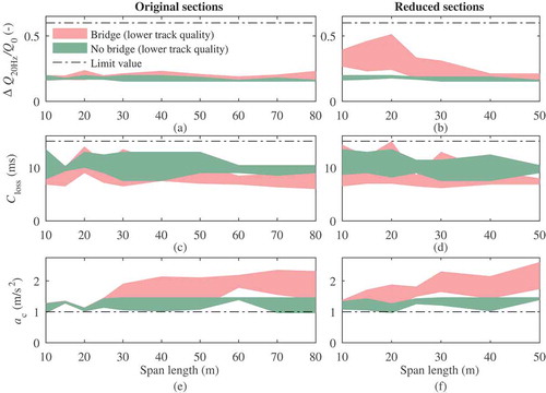
– The bridge response has little influence on the running safety indices, even for the shortest spans that reach the deck acceleration limit 5 m/s2.
– The wheel unloading and contact loss are instead very much dependent on the track quality level with higher wheel unloading for lower track quality and contact loss only at the lower track quality; see ) and ().
For the car body acceleration, ) shows that there is a low increase compared to a track section with no bridge for the spans up to 30 m. For the longer spans, on the other hand, the increase is around 1 m/s2. For the passenger comfort at the original cross-sections it can be observed that:
– The influence from the bridge response is low for the short span bridges for which the deflection limits are not reached.
– There is a considerable influence from the bridge response for the longer spans for which the deflection limits are reached. For these spans, the car body acceleration lies around the comfort limit 1 m/s2 for the smooth and the higher quality track profile; see (k).
– Additional excitation from irregularities at the lower track quality contributes to a decrease in comfort with car body acceleration above 2 m/s2.
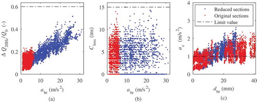
The above observations on running safety and comfort are confirmed from which shows the vehicle response against bridge response for all bridges in the study at the lower track quality. No apparent correlation can be seen between bridge acceleration and filtered wheel unloading (a) and contact loss (b) for the original cross-sections. For the car body acceleration in ), a trend of increasing car body response with increasing bridge deflection can be observed.
Figure 10. Vehicle response against bridge response at the most critical speed for the 24 profile realizations at the lower track quality for slab, beam and composite bridges in 1–3 spans: (a) filtered wheel unloading against bridge acceleration
, (b) contact loss
against bridge acceleration
and (c) car body acceleration
against bridge deflection
.
6.2. Reduced cross-sections
The reduced cross-sections were chosen to reach the deflection limit for all span lengths, as seen in ). The acceleration limit was then neglected and the resulting bridge deck acceleration is very high, 10–30 m/s2, for the spans up to 30 m; see ).
The filtered wheel unloading reach 0.4–0.5 for the shortest spans (10–20 m). This represents an increase from 0.2 at the reference track section with no bridge; see ). The bridges with the highest filtered wheel unloading have a reduction in stiffness of 60–80% compared to the original cross-sections, and bridge deck acceleration at 25–30 m/s2. These bridges are unrealistically weak compared to real bridges and would most likely be limited by the static design. The following can be observed for the running safety at the reduced cross-sections:
– The bridge response has an effect on the filtered wheel–rail force although the running safety limit (0.6) is not compromised.
– Contact loss does not automatically occur at bridge accelerations 1 g. Instead contact loss occurs only at the lowest track quality also for the bridges with bridge acceleration up to 30 m/s2.
) shows the relation between bridge acceleration and filtered wheel–rail force. The reduced cross-sections give rise to a wider range of resulting bridge acceleration (2–30 m/s2) compared to the original cross-sections (1–5 m/s2), and a correlation between bridge acceleration and filtered wheel unloading can be observed. There is no apparent trend in the duration of contact loss in ). This implies that the contact loss is likely to be more dependent on the vehicle–track interaction than the bridge response.
In relation to passenger comfort, ) shows that the car body acceleration increases for the track section with bridge compared to the track section without bridge for all span lengths. This result is in line with the fact that the deflection limits are reached for all the reduced cross-sections.
7. Conclusions
The running safety on non-ballasted bridges was assessed in a comprehensive parametric study based on the wheel–rail forces obtained from a 2D train–track–bridge model. The unfiltered wheel–rail force was shown to have a considerable high-frequency content from the wheel running over the irregular track. However, previous research has shown that short-time wheel unloading is not relevant for derailment. Consequently, safety indices based on duration of contact loss and filtered wheel unloading were adopted to determine whether the variations in the wheel–rail force pose any risk for derailment. It was shown that:
– The running safety indices for filtered wheel unloading (0.6) and duration of contact loss (15 ms) were not exceeded for any of the studied bridges or track sections.
– The filtered wheel–rail force was relatively insensitive to variations in the vehicle and track mechanical data.
– The vertical bridge vibration due to train loads had generally very little influence on the wheel–rail forces. Instead, the variations in the wheel–rail forces were highly related to the track quality and contact loss occurred only at the lower quality profile.
– Due to the high influence of the track irregularities the most sensible conclusions for the running safety on bridges could be drawn based on the comparison of running safety indices for trains running on a track section with and without bridge.
– Although a trend of increase in wheel unloading was seen for the bridges with very high deck acceleration (up to 30 m/s2), the deflection limit for passenger comfort according to EN 1990-A2 was reached before the running safety indices were compromised.
The car body acceleration obtained from the 2D model serves as a simplified estimate of passenger comfort. The results showed that the bridges for which the EN 1990-A2 deflection limit is reached induce car body accelerations around and slightly above the comfort limit 1 m/s2 for the smooth and the higher quality track profile. The relevance of a deflection criterion as a measure to ensure passenger comfort was thus confirmed. The sensitivity study showed that the car body acceleration is sensitive to the vehicle mechanical properties, which is why solid conclusions on the passenger comfort would require vehicle mechanical data that represent an envelope of real trains.
The inherent acceleration limit for ballasted bridges due to the risk of ballast instability is not present for bridges with non-ballasted track. Instead, the bridge deck vibrations need to be limited for running safety and passenger comfort. The present limit for non-ballasted bridges, 5 m/s2, has the underlying assumption that contact loss occurs at 10 m/s2 (1 g). The present study shows that high bridge deck accelerations, up to 30 m/s2, does not in itself lead to loss of contact. It should be noted that the 2D analyses neglect the influence from the lateral bridge vibrations on the train running safety, as well as other 3D effects such as twisting of the bridge deck. However, based on the present simulations of the vertical wheel–rail contact force, there is a potential in improving the EN 1990-A2 bridge deck acceleration criterion for bridges with non-ballasted tracks.
Acknowledgments
This work was made possible with the financial support from Trafikverket and the Railway Group at KTH Royal Institute of Technology, Stockholm. The simulations were performed on resources provided by the Swedish National Infrastructure for Computing (SNIC) at PDC Centre for High Performance Computing (PDC-HPC) at the KTH Royal Institute of Technology. Assoc. Prof. Daniel Cantero, NTNU Norwegian University of Science and Technology, is gratefully acknowledged for his part in establishing the numerical model which in the present paper has been further developed. Dr. Martin Li at Trafikverket and Prof. Mats Berg at KTH Royal Institute of Technology are gratefully acknowledged for providing measured wheel–rail forces from the Green Train project. Finally, Yu Sun at the State Key Laboratory of Traction Power, Southwest Jiaotong University in China is gratefully acknowledged for providing simulated vehicle response.
Disclosure statement
No potential conflict of interest was reported by the authors.
References
- Zhai W, Wang K, Cai C. Fundamentals of vehicle–track coupled dynamics. Vehicle Syst Dyn. 2009;47(11):1349–1376.
- Antolín P, Zhang N, Goicolea J, et al. Consideration of nonlinear wheel-rail contact forces for dynamic vehicle-bridge interaction in high-speed railways. J Sound Vib. 2013;332(5):1231–1251.
- Zhai W, Wang S, Zhang N, et al. High-speed train–track–bridge dynamic interactions - part II: experimental validation and engineering application. Int J Rail Transport. 2013;1(12):25–41.
- Montenegro P. A methodology for the assessment of the train running safety on bridges Doctoral thesis. University of Porto; 2015.
- Xia H, Zhang N. Dynamic analysis of railway bridge under high-speed trains. Comp Struct. 2005;83(23–24):1891–1901.
- Guo W, Xia H, Zhang N. Dynamic responses of Tsing Ma bridge and running safety of trains subjected to Typhoon York. Int J Rail Transport. 2013;1(3):181–192.
- Ishida H, Matsuo M, Fujioka T. Safety assessment method of railway vehicle under oscillatory wheel load fluctuation. J Environ Eng. 2007;2(2):407–418.
- Zhai W, Liu P, Lin J, et al. Experimental investigation on vibration behaviour of a CRH train at speed of 350 km/h. Int J Rail Transport. 2015;3(1):1–16.
- Arvidsson T, Karoumi R. Train–bridge interaction – a review and discussion of key model parameters. Int J Rail Transport. 2016;2(3):147–186.
- Museros P, Castillo-Linares A, Alarcón E Wheel–rail contact forces in high-speed simply supported bridges at resonance. In: Topping BHV, CA MS, editors. Proceedings of the Seventh International Conference on Computational Structures Technology. Civil-Comp Press, Stirling, Scotland; 2004. p. 1–20. Paper 223.
- Rocha JM, Henriques AA, Calçada R. Probabilistic assessment of the train running safety on a short-span high-speed railway bridge. Struct Infrastruct E. 2016;12(1):78–92.
- Chinese National Railway Administration. Code for design of high speed railway bridges. TB 10621-2014, Beijing, 2014, in Chinese.
- RTRI. Design standards for railway structures and commentary (displacement limits). Railway technical research institute, railway bureau of the ministry of land, infrastructure and transport government of Japan. Tokyo; 2007.
- CEN. EN 1990/A1, basis of structural design annexe A2. European committee for standardization; 2005.
- Zacher M, Baeßler M. Dynamic behaviour of ballast on railway bridges.In: Raimundo Delgado, Rui Calçada, José Maria Goicolea, Felipe Gabaldón (editors), Dynamics of high-speed railway bridges. London: Taylor & Francis Group; 2009. p. 99–112.
- ORED160. Permissible deflection of bridges. Office for research and experiments, RP 6 Final Report; 1988.
- ERRI D190. Permissible deflection of steel and composite bridges for velocities v > 160 km/h: parametric studies – summary and recommendations, Final report. European Rail Research Institute, RP 5; 1995.
- Ribeiro D, Calçada R, Delgado R, et al. Finite-element model calibration of a railway vehicle based on experimental modal parameters. Vehicle Syst Dyn. 2013;51(6):821–856.
- Arvidsson T, Andersson A. Train–track–bridge interaction for non-ballasted railway bridges on high-speed lines. Stockholm: KTH Royal Institute of Technology; 2017. ( TRITA-BKN Report 165.).
- Nadal J. Locomotives à vapeur. Encyclopédie scientifique, Bibliothèque de mécanique appliquée et génie. O. Doin, Paris; 1908.
- CEN. EN 14363, railway applications – testing and simulation for the acceptance of running characteristics of railway vehicles – running behaviour and stationary tests. European Committee for Standardization, Brussels; 2016.
- Matsudaira T. Dynamics of high speed rolling stock. JNR RTRI Quarterly Reports, Special Issue; 1963.
- CEN. EN 14067-6, railway applications – aerodynamics – part 6: requirements and test procedures for cross wind assessment. European Committee for Standardization, Brussels; 2010.
- Andersson E, Häggström J, Sima M, et al. Assessment of train-overturning risk due to strong cross-winds. Proc Inst Mech Eng Part F: J Rail Rapid Transit. 2004;218(3):213–223.
- UIC. Application and experience with ballastless track. International Union of Railways, Paris; 2008.
- Yang X, Gu S, Zhou S, et al. Effect of track irregularity on the dynamic response of a slab track under a high-speed train based on the composite track element method. Appl Acoust. 2015;99:72–84.
- Xia H. Dynamic analysis of high speed railway bridge under articulated trains. Comp Struct. 2003;81(26–27):2467–2478.
- Rocha JM, Henriques AA, Calçada R. Probabilistic safety assessment of a short span high-speed railway bridge. Eng Struct. 2014;71:99–111.
- Lei X, Noda NA. Analyses of dynamic response of vehicle and track coupling system with random irregularity of track vertical profile. J Sound Vib. 2002;258(1):147–165.
- Lou P. Finite element analysis for train–track–bridge interaction system. Arch Appl Mech. 2007;77(10):707–728.
- Dinh VN, Kim KD, Warnitchai P. Simulation procedure for vehicle–substructure dynamic interactions and wheel movements using linearized wheel–rail interfaces. Finite Elem Anal Des. 2009;45(5):341–356.
- Cantero D, Arvidsson T, OBrien E, et al. Train–track–bridge modelling and review of parameters. Struct Infrastruct E. 2016;12(9):1051–1064.
- Li MXD, Berggren EG, Berg M, et al. Assessing track geometry quality based on wavelength spectra and track-vehicle dynamic interaction. Vehicle Syst Dyn. 2008;46(1):261–276.
- Chaar N. Wheelset structural flexibility and track flexibility in vehicle–track dynamic interaction Doctoral thesis. Stockholm: KTH Royal Institute of Technology; 2007.
- Zhai W, Wang K, Lin J. Modelling and experiment of railway ballast vibrations. J Sound Vib. 2004;270(45):673–683.
- CEN. EN 1991-2 actions on structures - part 2: traffic loads on bridges. European Committee for Standardization, Brussels; 2010.
- Kouroussis G, Connolly D, Verlinden O. Railway-induced ground vibrations – a review of vehicle effects. Int J Rail Transport. 2014;2(2):69–110.
- DB. Requirements catalog for the construction of the permanent way, technical notification concerning the body of permanent way technology regulations. DB Systemtechnik, RO 03/2002 4th revised edition. Frankfurt; 1999.
- Claus H, Schiehlen W. Modeling and simulation of railway bogie structural vibrations. Vehicle Syst Dyn. 1986;29(1):538–552.
- CEN. EN 13848-5, railway applications – track – track geometry quality – part 5: geo- metric quality levels – plain line, switches and crossings. European Committee for Stan- dardization, Brussels; 2017.
- Trafikverket. Banöverbyggnad - spårläge - krav vid byggande och underhåll [track super- structure - track alignment - requirements for construction and maintenance]. TDOK. 2013;0347(version 4):2015.
- CEN. EN 13848-6, railway applications – track – track geometry quality – part 6: characterisation of track geometry quality. European Committee for Standardization, Brussels; 2014.
- Salcher P, Pradlwarter H, Adam C. Reliability assessment of railway bridges subjected to high-speed trains considering the effects of seasonal temperature changes. Eng Struct. 2016;126:712–724.
Appendix A. Train and bridge data
gives the assumed mechanical properties for the vehicle model. Axle distances are according to the EN 1991–2 [Citation36] HSLM-A moving load model. gives the cross-sectional properties for simply supported bridges in 1–3 spans. Original cross-sections optimized for both the acceleration and deflection limits are tabulated together with the reduced cross-sections optimized for the deflection limits only. For the continuous bridges, see [Citation19]. For the continuous bridges in 3 spans, the outer span length is ; in all other cases the span length is
.
Table A1. Assumed mechanical properties for the HSLM-A load model for train A1–A10 with symbols from .
Table A2. Mass and stiffness for the simply supported bridges. The properties for the 3 span bridges optimized for deflection differ from those of the 1–2 span bridges as the EN 1991–2 deflection limit is more stringent for simply supported bridges in three spans.