
 ?Mathematical formulae have been encoded as MathML and are displayed in this HTML version using MathJax in order to improve their display. Uncheck the box to turn MathJax off. This feature requires Javascript. Click on a formula to zoom.
Abstract
The work deals with the movement of military vehicles in operational areas following artillery fire, depending on munition type, fuze, and soil characteristics across different horizons. It adresses both the mobility of own forces within the operational area and the counter-mobility effects on enemy forces due to weapons' impact. Mobility assessment, including counter-mobility, is crucial for land forces and finds significant application in contemporary conflicts such as the Ukraine-Russia conflict. The objective of this study is to determine the dimensions of shell craters resulting from artillery fires on terrains with diverse soil compositions atop varying geological bedrocks. These craters may pose obstacles to military vehicles, thereby limiting their mobility. The primary contribution of this study lies in identifying fundamental methodologies for determining the depth and radius of shell crater effects caused by artillery munition. This includes experimental validation of theoretically calculated values and subsequent comparisons. This analysis of the battlespace carries implications for military decision-making processes in command and control. Consequently, the findings of this study offer insights into shaping terrain shelling strategies to render it inaccessible or determining the level of terrain penetrability following enemy fire. Key findings include the establishment of a comprehensive database and procedural frameworks for quantifying basic shell crater parameters. It is noteworthy that none of the theoretical procedures precisely matched the results obtained through experimental validation. Nonetheless, the experimental verification affirmed that created shell craters can become impassable obstacles for specific vehicles, and the procedure for determining this condition holds applicability to other vehicles.
REVIEWING EDITOR:
1. Introduction
The conduct of combat by frontline units is primarily defined by combat power, composition, combat phases, combat space, and its structure (Jančo & Kompan, Citation2023; Spisak & Pikner, Citation2023). One of the factors influencing these combat elements is the mobility of own assets relative to their ability to bypass obstacles or cross the gaps (Kompan, Citation2018). Specifically, the tactical-technical data (TTD) of vehicles in relation to environmental characteristics affects gap or obstacle crossing (Rolenec et al., Citation2021). Components of the natural environment, particularly the terrain surface, can be affected by enemy weapon systems, notably artillery and aviation, whose munition can create shell craters that serve as obstacles and impede the maneuver or mobility of land vehicle platforms (Heštera & Pahernik, Citation2018; Rybansky et al., Citation2014). Other factors such as weather, road network density, restricted areas, fire zones, key objects, and others, also influence the movement of task force units within military operations (Hujer et al., Citation2022).
All the aforementioned environmental factors are correlated with soil composition. Thus, resulting shell craters represent another factor that must be considered in combat activity planning to avoid inadvertently restricting the mobility of friendly forces or, conversely, effectively impeding enemy mobility. Conducting an area of operation analysis, including soil composition assessment, is a prerequisite for evaluating the potential impact of shell craters. Soil analysis is integral to joint operational functions (NATO Standardization Office, Citation2016), including maneuver and fires, force protection, command and control, and operations support.
Understanding soil composition and its significance is also reflected in specific tasks within tactical activities (Collins, Citation1998), such as gap crossing, breaching, obstacle construction, area/route denial or clearance, combat road construction/repair, support to forward aviation, fortifications, support to camouflage, concealment, deception, and explosive threat management. These tasks form a wide range of interconnected activities within engineer and fire support (Sustr et al., Citation2022).
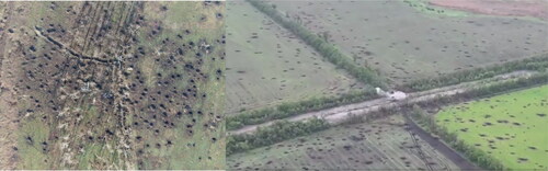
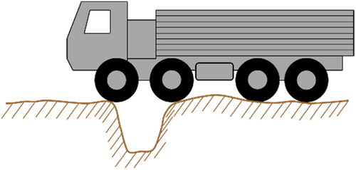
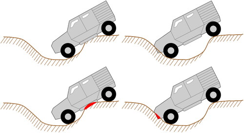
The assessment of route/area clearance post-artillery fire and its impact on terrain surface is minimally addressed in military expertise (Cibulova et al., Citation2017; Kompan & Hrnciar, Citation2021a). Currently, there is a scarcity of professional documents addressing this issue (Aji et al., Citation2021; Lappi et al., Citation2012). Although some scientific works on shell crater shapes exist, they primarily focus on World War I or II contexts (Magnini et al., Citation2016; Matos‐Machado et al., Citation2019). However, the relevance of this issue persists due to the integration of artillery operations in NATO countries' strategic concepts and plans, with artillery being a critical component of land operations in contemporary conflicts such as those in Ukraine and Nagorno-Karabakh. Mobility and counter-mobility are crucial in these conflicts, as evidenced by the Russian troop advancements in Ukraine, where artillery fire targeted movement points, crossroads, bridges, and infrastructure, affecting the mobility of other units, including second lines (see ) (Duncan et al., Citation2023). Achieving this effect necessitates the highest possible accuracy of artillery fire and appropriate target selection, including elements for firing and preparations (Ivan et al., Citation2021; Vajda, Citation2023; Varecha, Citation2020).
Figure 1. Examples of effects of artillery munition on terrain and their potential impact on vehicle mobility (Moon of Alabama, Citation2022).
The evaluation of surface and soil composition concerning the effects of own or enemy artillery fires and their munition effects, including the potential creation of shell craters as non-explosive obstacles, significantly impacts the mobility of own troops and the counter-mobility of the enemy. Therefore, the authors have set the main objective to define the resulting terrain condition following the explosion of selected artillery munition and its consequent effect on the mobility of land vehicle platforms. The primary research purpose is to verify and compare theoretical procedures, conduct experimental validation, and propose options for assessing terrain passability affected by shell craters.
The scientific contribution of this work lies in the correct application of methodology and selected scientific research methods. This hard system approach enables the comparison of obtained data and quantitative analysis, providing a foundation for the further development of empirical methods. The scientific research methods utilized in this work include analysis-synthesis (subchapter 2.4, chapter 3, and subchapter 3.1), structuring (subchapter 3.2 and chapter 4), measurement (chapter 4), and modeling (chapter 5). All these methods adopt a holistic approach to closely determine the effects of munition on asset mobility in the field.
2. Research methodology
2.1. Input data sources
The essential requirement for conducting the analysis is the availability of reliable data and information regarding the ammunition directly from the manufacturer. Furthermore, it involves data about soil composition within a soil horizon that are specified in current documents and regulations. Additional significant input data on shell craters in the blasting pits were obtained through field measurements during experimental verification.
Additional derived data necessary for the analysis was determined based on methodical arithmetic procedures (subsection 3.2.3). The analytical calculation method is executed within the framework of the geoinformation model, utilizing previously acquired geographical data, as outlined in section 5.
2.2. Data analysis
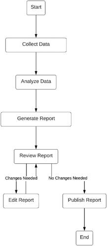
Analysis involves categorization of data based on whether they meet conditions (penetration into the soil profile and creation of a shel crater) under specific circumstances. This applies for all charges of the given ammunition. For the analysis, the possible impact angles are defined (simplified) into 3 levels - maximum, minimum, and medium level, as well as various impact velocities of the ammunition. Identification of penetration coefficients and disturbance coefficients are fundamental data entering calculations. Evaluation of the possibility of crossing the shell crater according to parameters is determined in the last step by a geoinformation model (see ).
Figure 2. Processing data in assessing terrain mobility after the effects of artillery munition.
2.3. Data flow diagram
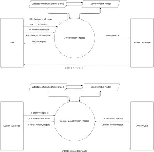
The context diagram, as well as the data flow diagram level 0 (see ), illustrates the basic entities (Unit and Staff of Task Force) between which communication occurs in the command and control system. This is a single high-level process that considers the fundamental steps of military units during planning, assuming the utilization of insights from databases created in this work. is divided into two areas (mobility area and counter-mobility area). This means that the data and information process is related to the needs of mobility of own units, respectively to measures restricting the movement of the enemy. This also achieves a greater scope in the tactical activities of the forces.
Figure 3. Data flow diagram of mobility and counter-mobility process.
2.4. Imput assumptions
Obstacles created by artillery munition could constitute a component applicable to engineer support within task groups. Such obstacles also hold significance in the Intelligence Preparation of the Battlefield (IPB). The fundamental prerequisites for utilizing obstacles created by artillery munition include:
Knowledge of artillery munition that can be used by own units or the enemy,
Knowledge of the soil composition in a soil horizon,
Knowledge of the types of vehicles against which the effects of these munition can be used to create obstacles (Rolenec et al., Citation2021).
Understanding these assumptions can significantly influence not only the maneuverability but also the overall objectives of the commander and the firepower of the affected units (Ivan et al., Citation2022). Given the artillery's capability for sustained operations, its extensive integration within the organizational frameworks of all armed forces, and the extensive utilization of artillery in modern conflicts, the artillery munitions and equipment chosen for the experiment were as follows (Farlik et al., Citation2014).
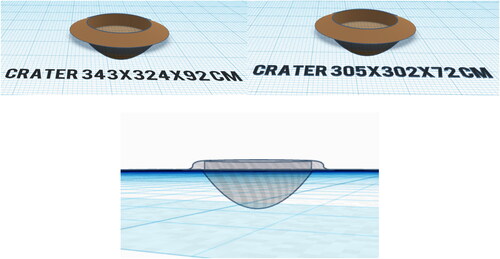
The primary research question was formulated as follows: how many instances (with specified mortar bomb velocity, angle of impact, and soil types) will result in the formation of a shell crater, and how many instances will only yield a deafening or concussive explosion without surface effect when using a 120 mm EOF-M mortar bomb? A shell crater is characterized as a paraboloid-shaped depression formed on the ground surface, typically accompanied by a mound of loose soil around its perimeter. The collected data will enable the determination of the theoretical diameters of the shell craters, which, along with the depth of the crater, influence the feasibility of crossing them by selected vehicles.
2.4.1. Munition types choosen for the experiment
A prerequisite for conducting the experiment is the availability of munitions capable of detonating and creating shell craters with dimensions that would restrict the capabilities resulting from the tactical-technical data of individual land vehicle assets (Rasico et al., Citation2018). The first assumption is thus met by artillery ammunition, rockets, and air munitions. Although there are other types of munitions capable of creating shell craters, these typically do not impose dimensional limitations on the movement of military equipment (e.g., tank munitions). The focal point of the problem is meant to be the need to reduce speed to avoid shell craters, or ideally, to completely prevent vehicle passage.
For the purposes of this work, four types of artillery munition were selected, of which the first mentioned type was further experimentally assessed not only in the blasting pits:
120 mm mortar bomb EOF-M;
152 mm artillery shell EOFD;
152 mm artillery shell EOF FeS;
152 mm artillery shell EOF-540.
This munition has now been supplied to the Ukrainian Armed Forces and utilized in the conflict with the Russian Federation. Additionally, for NATO's future requirements, calculations will also be conducted using 155 mm artillery munitions, which is the caliber for which a new weapon system in the form of the 155 mm CAESAR 8x8 CZ self-propelled gun is currently being introduced to the Armed Forces of the Czech Republic (Register of Treaties (in Czech), Citation2022; Danish Defence, Citation2023). The objective is to devise a solution that will allow the examination of the effects of various types of artillery munitions and the creation of a database detailing their impact on soil horizons.
The EOF-M 120 mm mortar bomb is described below for illustrative example and result only. The following limiting conditions were set by the authors for the experiment:
In the experiment, the calculation was performed for a standard 120 mm mortar bomb with a length of 0.737 m, whose body is uniformly filled with explosive. However, the lengths of individual projectile charges may vary by several mm, i.e. the charge may be filled unevenly. However, the effect on the bursting effect will be negligible. This does not impair the change in centre of gravity and ballistics (Beer et al., Citation2020).
Other limitng conditions:
Only the 120 mm mortar bomb is mentioned in the work, other artillery munition (the 3 types of 152 mm artillery shells mentioned above) is taken into account within the actual munition effects database.
The experiment is based on the assumption of homogeneous soil horizon. The solution of soil composition from multiple horizons is realistic, but is not the subject of this work.
Only specific TTDs of vehicles crucial for their mobility were selected for mobility verification. However, other factors such as traction, driver experience (applicable to crew vehicles), technical condition of the vehicles, and others can also significantly affect the TTDs that limit vehicle mobility. These additional conditions were not thoroughly analyzed in the initial phase, and only after verifying the impact of the first phase will the experiment be expanded to include other parameters.
The main assumption of the experimental verification is that its results align with the theoretical calculations (outlined in subsection 3.2). An additional assumption for experimental validation involves comparing the results of shell craters created using explosive charge versus those generated by 120 mm mortar bombs EOF-M on blast pits. Detailed descriptions of the experiments are provided in Chapter 4.
2.4.2. Selected transport and combat assets
Combat and transport vehicles of the frontline units, which may be affected in movement by the disturbed surface, i.e. by the created shell craters, will usually be tracked - tanks, armoured vehicles and wheeled - infantry fighting vehicles, trucks. However, the created shell craters may also affect the movement of artillery units, main supply routes or even second-line command posts on both sides of the battlefield. This is a side effect of artillery munition, as that artillery munition are not primarily used for this purpose. In addition to the actual classification of vehicles by type of purpose, the following basic parameters of wheeled vehicles with regard to the width and depth of the shell craters must be observed:
Whellbase;
Groud clearance.
The effect of munition on the ground surface (shell crater formation) throughout the soil profile can be specified for individual munition and individual vehicle types. It is generally accepted that tracked vehicles have better ground clearance and obstacle crossing capability than wheeled vehicles, yet even tracked vehicles have their limits. This implies that for each vehicle there is a certain shell crater size that the vehicle can no longer cross.
3. Approaches to assessing the dimensions of artillery shell craters
The basic physical characteristics of the shell craters are the width, depth and wall angle of the shell crater walls formed by the compressive action of the bursting munition fragment in the soil profile (Joshi & Panigrahi, Citation2023). These are situations where the blast is explicitly manifested on the soil surface. In certain cases, deafening and concussive blasts may also occur, but they do not occur themselves on the surface by forming a shell crater and therefore have little or no effect on vehicle mobility.
The first prerequisite for assessing the depth of artillery shell craters is that there are fuzes for artillery shells and mortar bombs that allow the shells and bombs to penetrate to a certain depth in the soil (Wang et al., Citation2015). This assumption is fulfilled because today's standard fuzes allow delayed initiation and may also be fitted with mechanical features that further prolong initiation. This type of fuze is also standard on the 120 mm mines used in the experiment.
The second assumption is that the delay in setting the fuze is sufficient to allow the shells (bombs) to penetrate to the theoretically calculated depth. This assumption is based on Janečka (1989), where it is stated that the equation was determined experimentally based on numerous tests and later also proved theoretically. Therefore, calculations of the uniformly slowed motion of the shells (bombs) penetrating the soil to verify the depth with respect to the impact velocity, angle and time delay of the fuzes are not performed within the work.
3.1. Parameters of shell craters after effects of artillery munition
The shell craters produced by artillery munition vary according to the fuze setting or soil composition at the impact site and impact values. Shells (bombs) can impact at different angles, velocities and with different fuze settings. These variables will affect the depth of penetration of the shell (bomb) into the soil profile. These are important parameters that affect the formation of shell craters, their shape and size. Soil composition varies in different areas. It may also vary in that it may be a homogeneous or layered soil composition (Jensen et al., Citation2021). In a homogeneous soil composition, only one soil horizon is present.
In the Czech Armed Forces, procedures and equations have been established to determine the size of the shell crater after a munition explosion (Beer et al., Citation2020; Janečka 1989; Ministry of Defence Czech Republic, Citation1981). In the next subsection, the individual procedures are described and their accuracy is verified in an experiment.
3.2. Theoretical calculations
3.2.1. Berezansky equation
The first equation to calculate the depth of the shell crater is the Berezansky equation, which can be considered complex in order to determine the depth of penetration of the shell and bomb (dp). In a very solid substrate composition (reinforced concrete, solid rock), the trajectory of the shell (mine) (s) curves. In a low-strength soil composition (e.g. sand, firm clay), the shell (bomb) moves almost in a straight line (Janečka 1989). The authors of this work use the soil composition distribution proposed in (Janečka 1989; Ministry of Defence Czech Republic, Citation1981).
(1)
(1)
dp is the depth of penetration in metres measured normal to the surface of the obstacle from the tip of the shell (bomb);λ1 is coefficient influenced by the shape of the shell (bomb) tip:λ1 = 1.0 for round ogive shell (bomb) and armour-piercing shell (bomb) at
;λ1 = 1.3 for shell (bomb) with a tipped ogive
;λ2 is coefficient dependent on the calibre of the shell (bomb):λ2 = 0.9 for d ≤ 75 mm;λ2 = 1.0 for 75 mm < d ≤ 210 mm;λ2 = 1.3 for d > 210 mm (for all shell (bomb) whose P ≤ 2500 kg);Cp is coefficient of penetration determined experimentally (Janečka 1989);M is the weight of the shell (bomb) in kilograms;c is the calibre of the shell (bomb) in metres;v is impact velocity of the shell (bomb) in m·s−1;α is impact angle;n is coefficient of curvature of the shell (bomb) trajectory in the soil layers:n = 1.0 for soft (noncompacted) soil;n = 1.5 – 1.8 for solid compacted soil and shots with a tipped ogive;n = 2.0 – 2.5 for solid compacted soil and round ogive shells (bombs).
shows the values of the penetration coefficients determined experimentally and the disturbance coefficients for each type of surface (Janečka 1989). These are coefficients that are proven and used for military tasks. Surface types numbered 1-8 are rated as soft, while surfaces 9-13 are rated as hard to very hard.
Table 1. Penetration coefficients and the disturbance coefficients (Janečka 1989).
In some cases it is necessary to calculate the depth of penetration of the shell (bomb) into the layered soil composition. The different layers are usually characterised by different Cp coefficients.
Procedure in case of a layered soil:
The penetration depth is determined for the first layer (dp1), which is characterized by a certain penetration coefficient (Cp1) and a certain thickness (h1):
(2)
(2)
(curvature of the path in a soft soil composition is not considered);
If calculated : the shell (bomb) stops in the first layer.
If calculated : the shell (bomb) penetrates the next layer, which is characterized by kp2, h2 (or b or c). The other parameters of the equation such as λ1, λ2, P, d, v are invariant and need not be considered further.
The penetration depth for layer 2 is determined:
The total depth of penetration is calculated from the relationship:
(4)
(4)
The issue is further addressed only in a homogeneous soil composition in order to establish a primary overview of the effects of artillery munition. Layered soil will be addressed in the future in relation to homogeneous composition.
3.2.2. Effects of an explosion in a homogeneous soil composition
To determine the radius of the shell crater, the first step is to determine the radius of disturbance, which is used to judge whether a shell crater or just a deafening or concussive explosion will occur. A homogeneous soil composition means that a predominant soil type is present throughout the area of potential shell crater formation.
To calculate the radius of the disturbance, the following equtation applies (Janečka 1989):
(5)
(5)
is radius of disturbance in meters;N is weight of the charge in kilograms equivalent of TNT;Kr is disturbance coefficient. It takes into account the perfect sealing of the charge.
3.2.3. Effects of an explosion in a homogeneous soil composition
To find the radius of the shell crater, it is necessary to first calculate the radius of the disturbance (). The equation for calculating the radius of the disturbance is valid under the condition of perfect sealing of the tearing charge of the shell (bomb), which satisfies the relation (Janečka 1989):
(6)
(6)
h is the depth of the centre of the shell (bomb) under the surface of the obstacle.
If this relationship does not hold, the effect of the explosion is determined on the surface of the obstacle by the formation of a shell crater and is greatly reduced towards the depth.
If the depth of placement of the explosive charge of the shell (bomb) is , the radius of disturbance will be smaller and the radius of ejection will be larger than the resulting data from the equation for calculating
The actual radii of disturbance are calculated by the sealing coefficient m1 and m2. The coefficient m1 indicates how the radius of disturbance decreases at a lower degree of sealing than assumed by Kr. The coefficient m2 indicates how the radius of ejection and spalling increases at a certain sealing. However, this coefficient is not discussed further in the work.
To determine the coefficients m1 and m2, the degree of sealing ε must be calculated in advance:
(7)
(8)
(8)
h is the depth of the centre of explosive charge below the surface of the obstacle;δ is the protruding part of the length of the explosive charge;lN is the length of the explosive charge.
An recessed charge is one in which the entire body of the shell (bomb) is below the ground surface. For a partially recessed charge, part of the charge is below the ground surface and part is above the ground (in this situation the stabiliser and other parts of the shell (bomb) are not considered).
According to the calculated value, the values of the coefficients m1 and m2 (Janecka, Citation1989) are added to the Equationequation 9(9)
(9) :
(9)
(9)
In the case of calculating the equivalent of a TNT charge relative to the charge in a given type of artillery munition, it is also necessary to calculate the ballistic coefficient and the sealing coefficient (see first experimental verification).
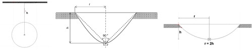
shows an example of a deaf explosion with no determination on the ground surface, as well as the effect of a normal explosion (h = r) and also a reinforced 2-fold explosion (r = 2h). The view of the explosive charges and shell craters is from the side.
Figure 4. Order from left: deaf explosion without surface determination; normal explosion; double explosion. h is the depth of the centre of explosive charge below the surface of the obstacle; r is the radius of the shell crater.
The shows the depth of the centre of explosive charge below the surface of the obstacle (Janecka, Citation1989). The impact angle of the mortar bomb has also been taken into account. The values in the light grey cells mean that the explosion does not occur on the surface. This is a so-called deaf or concussive explosion. For the values in the white and dark grey cells, the explosion will reveal itself on the surface by the creation of a shell crater. Values in dark grey cells mean that the charge is partially recessed (refers to the explosive charge and does not take into account the stabiliser) and the shell crater formation will be minor. The distribution is also necessary for further calculations to determine the m1 and m2 coefficients.
Table 2. Possibility of shell crater formation after the explosion of a 120 mm mortar bomb with different charges and in different soil composition.
In case of a 120 mm EOF-M mortar bomb and its explosion in soil composition, it can be stated that only a small proportion of all cases will manifest themselves without effect on the surface, i.e. a deaf or concussive explosion. This can be due to loose soil when the mortar bomb penetrates deep into the subsoil. For the vast majority, a shell crater of varying paraboloid shape will form on the surface, i.e. it depends on the depth of the mortar bomb blast. In solid and very strong strength composite soil, the shell crater will be of small radius as their penetration into the soil composition is very short. As a rule, in these cases only the material at the blast site (e.g. concrete block) will be destroyed. This may apply, for example, to airports, roads, highways and other paved areas or natural hard rock.
and shows the depth of the centre of explosive charge. Negative values in mean that the shell (bomb)'s center of explosive charge is above the surface. Values below the red curve indicate the formation of a shell crater. Values above the red curve indicate a deaf or concussive explosion. The type of soil composition corresponds to .
Figure 5. Delineation of the boundary between the occurrence of a shell crater and a deaf or concussive explosion in soft soil composition.
Figure 6. Delineation of the boundary between the occurrence of a shell crater and a deaf or concussive explosion in solid and very solid soil composition.
3.2.4. National military regulation for blasting works
This document (Ministry of Defence Czech Republic, Citation1981) is for the use of the Czech Army corps of engineers to calculate explosive charges for each type of material, and therefore to calculate charges to produce the required shell craters size. From this equation it is possible to associate an equation to calculate the shell crater radius assuming knowledge of the type and weight of the charge. In this calculation there are variables such as: weight of the explosive charge, soil composition coefficient, coefficient of trench and shell crater radius.
3.2.5. Blast effect calculations by Department of Weapons and Munition
One of the approaches to calculate blast effect was developed in the Department of Weapons and Munition, University of defence. Blast effect calculations, and especially earthwork charge calculations, typically use various coefficients characterizing the mechanical and physical properties of the blast environment and various empirical and semi-empirical relationships (Henrych, Citation1973).
To determine the basic dimensions of the shell crater and to assess the size (radius) of the individual bands of the rupture effect, the following empirical relations can be used (Beer et al., Citation2020; Henrych, Citation1973):
(9)
(9)
for soft soil composition;
for solid and very solid soil composition.
is shell crater radius (m);
is soil composition coefficient;
is the weight of the actual explosive used (TNT kg);
is the depth of the explosion;
is the visible depth of the shell crater;
is radius of destruction.
4. Experimental verification
First experimental verification was carried out within the blasting works at the blasting pit Hanácká Louka in military training area Březina, Czech Republic to compare the shell crater values calculated according to various documents (Beer et al., Citation2020; Janecka, Citation1989; Ministry of Defence Czech Republic, Citation1981).
For the experimental verification, 120 mm EOF-M high explosive mortar bomb was used. Furthermore, the conditions was set as if the munition detonates in soil composition (kp = 40) after being fired with Charge 4 at an angle of 85°. Charge 4 was determined because of the possible future comparison of artillery fires with the effects of the calculated charge.
As part of this experiment, it was necessary to determine the ballistic coefficient and the sealing coefficient due to the use of TNT charges as an equivalent replacement for 120 mm EOF-M mortar bomb:ballistic coefficient kB = weight of package/weight of explosiveweight of package of 120 mm EOF-M mortar bomb = 13.34 kgweight of explosive of 120 mm EOF-M mortar bomb = 2.66 kg
(10)
(10)
sealing coefficient kE = 0.2 + (0.8/(1 + kB)) = 0.333
High explosive (H), like hexogen, is converted to TNT equivalent with maximum potency (1.5x). This maximum potency is based on the National military regulation for blasting works, which is a mandatory document within the ACR for blasting works. There are also other documents that specify the coefficient for each type of explosive.
From the given calculations it follows that a 120 mm high explosive mortar bomb is equal to the weight of a charge equivalent to 9.78 kg of TNT.
According to the equation (Janecka, Citation1989), the location of the centre of explosive charge at a depth of 0.78 m below the ground surface was calculated. For the calculation an assumption of homogeneous soil composition, was confirmed in the experimental verification.
Pressed TNT was chosen for the equivalent explosive charge to the artillery munition. 1 kg and 400 g TNT loads were used, weighing a total of 9.8 kg, which, when assembled into a shaped charge corresponded to the shape of the 120 mm EOF-M munition (see ). However, due to the strength of the casing (in the form of soil composition) and the dimensions of the mortar bomb, the effect is close to that of a concentrated charge. The method of initiation was safety fuzed using a detcord. The excavated pit with the placed charge was covered with soil composition to the level of the surrounding terrain.
Figure 7. Left - placing of the explosive charge in the soil. Right - the shell crater formed.
The effect of the explosive charge was creation of shell crater with dimensions from 2.84 m to 2.66 m (width) by 1.14 m (depth) in the shape of a paraboloid. This may be due to the angle of the placed charge corresponding to the artillery shell after impact, while the soil composition around the explosive charge may have been partially different. The shows comparison of experimental verification values with calculated values:
Table 3. Comparison of experimental verification values with calculated values.
The shows that the values calculated theoretically differ from those verified experimentally in the blast pit. The value of the shell crater radius is closest to the document (Ministry of Defence Czech Republic, Citation1981) and the value of the shell crater depth is closest to the calculated value according to the document from Beer et al. (Citation2020). It should be noted that the depth by document (Janecka, Citation1989) applies to the penetration of the mortar bomb into the soil surface, without the effects of the explosion. The resulting depth of the shell crater after the explosion is influenced by the recoil of the soil (dependence of the amount of explosive on the depth of the explosive charge) or even by the collapse of the soil. The equations by which the values of depth and radius of the shell crater were calculated are given below.
Second experimental verification was carried out to compare shell crater values calculated according to various documents within the framework of blasting works at the Polečnice training area in VVP Boletice.
For experimental verification, 120 mm mortar bomb (with a fragmentation charge of 2.66 kg TNT/H/E) was specified. Furthermore, the conditions that the mortar bomb detonates in soil composition (kp1 = 45 and kp2 = 55) with a charge of 4 at a 45° angle were determined. It has been chosen two different soil compositions (each mortar bomb at different depth) for calculations and experimental verification, which were closest to the real condition in the Boletice - Polečnice military training area and could be compared to each other. A charge 4 was determined because of possible future comparison of artillery fires with the effects of the calculated explosive charge. The equation (Janecka, Citation1989) was used to calculate the location of the centre of charge at a depth of 0.653 m (kp1) and 0.847 m (kp2) below the ground surface. Another assumption was the presence of homogeneous soil composition, which was confirmed in the experimental verification.
The method of initiation was the safety fuzed with a detcord and a booster placed in fuze socket. This solution allowed to iniciate the mortar bomb in the same manner as with the actual fuze. The excavated pit with the placed charge was backfilled with soil composition and leveled to the level of the surrounding terrain (see ).
Figure 8. Placing a mortar bomb in the soil composition during experimental verification.
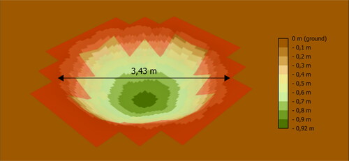
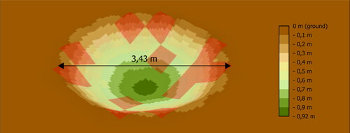
The effect of the explosive charge (in the kp1 soil composition) created a shell crater with dimensions from 3.24 m to 3.43 m (width) and from 0.89 m to 0.92 m (depth) in the shape of a paraboloid (see ). The longer side of the paraboloid is due to the placed mortar bomb corresponding after the impact angle, at the same time the soil composition around the explosive charge may have been partially different. The height of the embankment around the formed shell crater reached up to 0.27 m at the closest point of the paraboloid edge.
The effect of the explosive charge (in kp2 soil composition) created a shell crater with dimensions from 3.02 m to 3.05 m (width) and from 0.72 m to 0.75 m (depth) in the shape of a paraboloid (see ). The longer side of the paraboloid is due to the placed mortar bomb corresponding after the impact angle, at the same time the soil composition around the charge could be partially different. The height of the embankment around the formed shell crater reached up to 0.27 m at the closest point of the paraboloid edge. The largest single pieces of dirt measured up to 0.3 m.
Figure 9. A shell craters formed in the soil composition kp1 and kp2.
The shows that the values calculated differ from those verified experimentally in the blast pit. Based on the values calculated and experimentally verified, it can be determined that the closest agreement exists for the soil composition with kp2.
Table 4. Comparison of second experimental verification values with calculated values.
Comparison of experimental verification values with calculated values:
The value of the radius and the depth of the shell crater are closest to the value according to Beer et al. (Citation2020). It should be noted that the depth equation (Janecka, Citation1989) is valid for mine penetration into the soil without blast effects, while the shell crater radius is calculated according to the blast. This depth value also became the basic data for further calculations according to Beer et al. (Citation2020).
The first and second experimental verification allowed to compare the theoretically calculated values with those obtained by verification in an environment close to combat conditions. The experiment revealed:
There is a deviation from the theoretically calculated values;
It is advisable to perform another experiment to verify the observed deviations and compare them with the theoretically calculated values. The values calculated theoretically according to Beer et al. (Citation2020) are almost identical to those obtained from the experiment performed and therefore these calculations can be considered reliable. Therefore, the values can be used in the decision-making and planning process and in the analysis of the area of operation in terms of unit mobility with respect to artillery shell craters. At the same time, they represent the basic input data for determining the threshold values for the key TTD of individual vehicles of a combat formation with respect to their ability to cross artillery shell craters in the area of operation.
5. Determination of limit values for mobility allowances of selected vehicles
The size of the shell craters (depth, slope, radius), their distance from each other are basic indicators for comparing the limit values of individual vehicles to the possibility of movement in the terrain disturbed by these shell craters or when crossing them themselves. There are two ways to cross shell craters. The first is to cross them directly and the second is to avoid them (Rybansky et al., Citation2020). In both cases, the progress is slowed down and at the same time it is desirable not to get the unit stuck.
Avoiding the obstacle seems to be a more effective way, however, from a tactical point of view, this manoeuvre can cause a negative effect on the evolution of unit movement, especially where the spatial distribution and the amount of shell craters created reach higher values (Barni et al., Citation2000). Their avoiding may be risky from the point of view of cover, or the geographical characteristics of the environment may not allow this possibility. The specific area of the battlefield where shell craters are present after artillery activity can be classified in terms of terrain traversability as the degree of manoeuvrability of a vehicle (Hupy, Citation2006) in a given area in order to traverse that area (see ). An approximate determination of the terrain passability of a given area for a particular vehicle can be determined as follows, based on knowledge of the number of shell craters present and their areal extent:
Table 5. Approximate determination of terrain passability based on shell crater size.
where the coefficient of passability of terrain affected due to the existence of shell craters (ATSC) can be expressed by
(11)
(11)
where ASC represents the horizontal area of all shell craters in m2 and A represents the area of the area of interest in m2. Three classes of terrain passability, GO (passable terrain), SLOW GO (low-passability terrain) and NO GO (impassable terrain), are defined in NATO standardisation agreements (NATO Standardization Office, Citation1975; Citation1999). The determination of the intervals of these classes for the assessment of terrain passability affected by the existence of shell craters is based on the definition of limits (tresh holds) for similar objects of a flat character (forests, swamps) in the Polish Automatic Military Passability Map Generation System (Pokonieczny, Citation2017).
In order to assess the possibilities of straight cross of the shell crater, it is necessary to know the tactical-technical parameters of the vehicle and the dimensions and shape of the shell crater. The shell crater can be classified as a micro-relief object of terrain relief and the assessment of the possibility of crossing it can be approached on the basis of a comparison of these parameters, where in the final stage it is possible to determine whether the vehicle is able to cross the shell crater or not (Dohnal et al., Citation2019).
The simplest method of straight crossing the shell crater is shown in , which satisfies the condition that a shell crater is narrower than the vehicle's crossing ability (this method is particularly valid for multi-axle wheeled vehicles or tracked vehicles).
Figure 10. Crossing the obstacle directly straight.
If the shell crater is wider than the vehicle's crossing ability and the width (diameter) of the shell crater is larger than the vehicle's track, the following two cases can occur for wheeled vehicles, with a certain degree of schematization and simplification of the problem (not considering the vehicle's lateral inclination, suspension, etc.) (see ):
Figure 11. Examples of constraints when crossing an obstacle.
The angle of the top edge of the microrelief object is less than breakover angle;
The angle between the relief and the microrelief is greater than the approach angle of the vehicle.
A more detailed description of the calculation method for both variants is described in Dohnal et al. (Citation2019). From a tactical point of view, this method can be used to accomplish a task where it is necessary to determine the feasibility of passability a given terrain for a specific vehicles, if data on terrain relief that is already affected by artillery activity (e.g. data obtained from UAVs) is available. In the case where the task is to make a given area (a specific location) impassable (slowed down) by artillery activity for a specific wheeled vehicle, the following calculation procedure can be used to simplify and schematize the problem, in the sense of considering only the projection of the vehicle's side axis as the axis of movement.
In the calculation of the first case (, bottom left), the initial condition is that the vehicle entry and exit angle β (breakover angle) has to be greater than the shell crater wall angle α for the wheeled vehicle to cross the obstacle. The vehicle crossing angle β can be calculated by Equationequation 12(12)
(12) and the shell crater wall angle α, assuming a cone shell crater parameterisation, by Equationequation 13
(13)
(13) .
(12)
(12)
(13)
(13)
where GC is the ground clearance in m and WB is the wheelbase in m. The above procedure can be demonstratively applied to determine the possibility of crossing shell crater no. 1 created during the experimental trial to verify the theoretical calculations of the shell crater parameters, despite the fact that the diameter of the shell crater is smaller than the wheelbase of the selected two-axle wheeled vehicles (see ). For this purpose, the values given in were used for the calculation. The following shows the results for the three two-axle wheeled vehicles used in the ACR.
Table 6. Selected wheeled vehicles used in the Czech Armed Forces.
Table 7. Evaluation of the possibility of crossing the shell crater according to parameters determined by different methods.
It can be seen from that if the vehicle were to enter the shell crater in the direction of the left or right wheels on its centreline, the vehicle chassis would come into contact with the ground. This does not mean that the vehicle will not cross the shell crater, but merely draws attention to the fact that the vehicle, even taking into account the soil characteristics, may become stuck in the shell crater.
The calculation method is also processed within the framework of the geoinformation model, which works with the already obtained geographical data, especially the information about the terrain relief, which is the main component of the calculation. The input relief model is a digital relief model in raster form with a spatial resolution (pixel size) of 0.5 m. shows the output of the model with a 3D representation of the shell crater. The red colouring of the edge of the shell crater represents the model output in pixel form, which in this case indicates the locations of possible chassis contact with the terrain for the Toyota Hilux vehicle.
Figure 12. Model output with 3D representation of the shell crater.
For the second case (see , bottom right), where the vehicle hits the opposite wall of the shell crater, the mathematical model was expressed as follows based on the schematisation of the model case (). If Equationequation 14(14)
(14) is satisfied, there will be no frontal impact of the vehicle with the shell crater wall and therefore no entrapment of the vehicle in the shell crater.
Figure 13. Schematisation of a model case of entrapment in a shell crater.
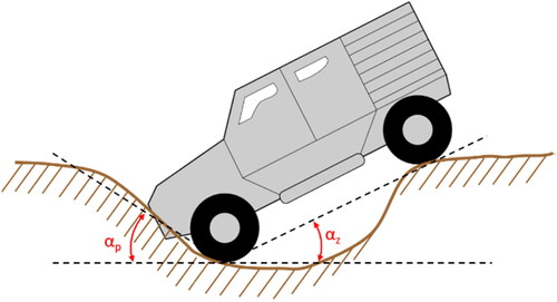
where αp is the front angle, αz is the rear angle and αa is the front approach angle. The front angle αp is enclosed by semi-lines drawn from the point of contact of the front wheel with the ground, one semi-line being drawn in the horizontal plane and the other intersecting a point on the ground at a distance from the front overhang of the vehicle. The rear angle αz is enclosed by semi-lines drawn from a point of contact between the centre of the front wheel and the ground, one semi-plane being drawn in a horizontal plane and the other intersecting a point of contact between the rear wheel and the ground. The front and rear angles cannot be calculated unambiguously without ignoring the surrounding terrain of the shell crater. The relative heights at the point of contact between the wheels and the front of the vehicle and the terrain, which can be modelled on the basis of the specific position of the vehicle in the terrain, enter into the calculation.
Similar to the previous method, the calculation process is processed by a geoinformation model. The input data for this method is also a digital relief model in raster format with a resolution of 0.5 m. shows the output of the model in 3D and, as in the previous method, the red colouring of the pixels at the edge of the shell crater represents the locations where a frontal impact of the vehicle on the shell crater wall may occur.
Figure 14. Model output with 3D representation of the shell crater.
The schematization and mathematical parameterization of the model calculations do not fully reflect the real conditions of the environment and vehicle movement in the field. However, the outputs of the models can be used in the decision making process for operation planning. Local (natural) conditions can change rapidly during troop operations, and this fact must be taken into account.
At the same time, the above computational methods can be used to evaluate the battlefield environment that is affected by artillery munition in UGV systems that can automatically assess the environment and search for the optimal route (Dawid & Pokonieczny, Citation2021; Nowakowski & Kurylo, Citation2023). Alternatively, the optimal route can be given to the UGV based on simultaneous measurements by, for example, an airborne support UAV and its equipment (LIDAR).
Thus, the limit of the shell (bomb) ejection charge and the angle of impact of the munition on the soil composition can be determined for individual munition and individual assets so that the movement of the vehicles is theoretically realistic with respect to the TTD.
The shows the TTD limit values of the selected vehicles. These values become the limit due to the dimensions of the shell craters. In this case, however, no account is taken of adhesion and possible uneven balance.
Table 8. Comparison of limited tactical and technical data of selected vehicles.
On the basis of the given TTDs of individual vehicles, calculated values of shell craters (depth, width) it is possible to compare the crossing of obstacles, and in a broader context also the mobility across the designated area, the battlefield. This is an important factor not only in the context of operation planning, but also in solving operational tasks during the operation.
6. Discussion
Aerial and other munition are not discussed further in this work, but may provide further initiative to extend the database of munition effects on soil composition.
Another objective of the authors is to compare the values determined from theoretical calculations with those obtained through experimental verification and the shell craters formed after actual artillery fires. The creation of shell craters following real artillery fire reflects genuine conditions, unlike those modeled by engineer explosive charges or dug and refilled wells for mortar bombs or other munitions. Another area of research involves resolving soil composition across multiple horizons. This expands upon the fundamental research addressed in this work and facilitates precise analysis across all operational areas of troops.
In the case of artillery fires on the terrain, simulated calculations (Chen et al., Citation2021) or using the app like MASA Sword can determine the number of shells (bombs) to a given obstacle width and depth relative to each counter-mobility effect. This can also be used to compare the material requirements in terms of minefields established versus obstacless created by artillery fire.
Currently, neither the ACR land forces command and control system nor the engineer command and control subsystem contains such an application that would address that issue.
This issue can also be taken into account in the scope of weapon intelligence team (WIT) units (Aji et. al 2021), which are currently becoming an integral and important part of foreign operations within NATO EOD units. The subject of the article was discussed with specialists from the Centre of Technical and Information Support who confirmed its uniqueness. The issue of WIT in ACR is embedded in the EOD Unit Training Programmes from 2020 onwards. Therefore, munition effects can be further addressed and developed to determine the distance and type of munition relative to the identification of possible enemy effects. For example, an unconventional enemy that operates in small units, as it was common in the Afghanistan.
7. Conclusion
Artillery fires directed at the terrain to achieve the desired effect of impeding the mobility of enemy assets represent one of the potential counter-mobility measures in fire support. The responsibility for requesting such fire support falls on engineer staff officers, who identify unplanned obstacles and develop obstacle plans within engineer support (Rolenec et al., Citation2022). Consequently, engineer specialization staff officers must monitor not only engineer assets but also other assets capable of creating obstacles. This approach serves as a means to restrict or prevent enemy movement in areas where engineer units are unable to conduct obstacle tasks. In the context of counter-mobility, these effects can mirror those employed in frontline units' fire systems. Such effects, including blocking, disrupting, fixing, and turning, can be effectively utilized with artillery fires, establishing non-explosive shell craters as obstacles (Yavuz et al., Citation2019). In certain scenarios, artillery fires may be employed to destroy specific targets, resulting in the creation of shell craters as a secondary effect. Therefore, it is essential to assess the affected area to determine if it remains usable (passable) by vehicles. Establishing a database to identify the depth and radius of shell craters in a homogeneous environment is a critical step in determining movement restrictions for both combat and transport vehicles. This process facilitates the easier identification of constraints related to mobility or counter-mobility, as well as the required distances or angles for artillery munition impact during operations aimed at achieving the desired effect and ensuring operational execution and sustainability in areas contaminated with explosive threats (Kompan & Hrnciar, Citation2021b). Thus, surprise momentum against the enemy and their activities can be achieved. Simultaneously, from the perspective of troop mobility, this approach offers a means to address the transportation challenge posed by obstacle crossings using selected assets. The issue of vehicle mobility and terrain passability is also pertinent in the ongoing conflict in Ukraine, where artillery munitions are extensively employed by individual troops. Moreover, as the front shifts, the landscape containing these shell craters also evolves, impacting the movement of all vehicles. The established shell craters, serving as non-explosive obstacles, offer a rapid means of establishing obstacles in future conflicts. Unlike explosive obstacles, this non-explosive option poses no threat to civilian populations (in terms of collateral damage) or to troops themselves. Additionally, their removal doesn't entail the same level of risk as the clearance of explosive threats. The challenges associated with clearing minefields, including issues such as unaccounted-for data, soil composition erosion, and other effects, have been evident in previous armed conflicts worldwide (e.g., in the states of the former Yugoslavia). The only potential issue may arise from failed artillery munitions that remain in the soil.
Author's contributions
Conceptualization: M. Sedláček, F.D. and J.I.; Data curation: M. Sedláček; Formal analysis: M. Sedláček, F.D., J.I. and M. Su; Funding acquisition: M. Sedláček, F.D., J.I. and M. Su; Investigation: M. Sedláček, F.D., J.I. and M. Su; Methodology: M. Sedláček, J.I. and M. Su; Project administration: M. Sedláček, F.D., J.I. and M. Su; Resources: M. Sedláček, F.D., J.I. and M. Su; Software: M. Sedláček and F.D.; Supervision: M. Sedláček, F.D., J.I. and M. Su; Visualization: M. Sedláček and F.D.; Writing - original draft: M. Sedláček, F.D., J.I. and M. Su; Writing - review & editing: M. Sedláček, F.D., J.I. and M. Su.
Disclosure statement
No potential conflict of interest was reported by the author(s).
Data availability statement
The data that support the findings of this study are available from the corresponding author, [MaSe], upon reasonable request.
Additional information
Funding
Notes on contributors
Martin Sedláček
Martin Sedláek is an assistant professor at the Department of Engineer Support, University of Defence, Brno. His research is aimed in the effects of explosives in conditions of engineer support in the role of mobility and counter-mobility.
Filip Dohnal
Filip Dohnal is an assistant professor at the Department of Military Geography and Meteorology, University of Defence, Brno. His research is aimed in geographical conditions and their influence on the mobility of military vehicles.
Jan Ivan
Jan Ivan is an assistant professor at the Department of Fire Support, University of Defence, Brno. He deals with the implementation of joint fire support, especially the tactics of artillery units in degraded operations.
Michal Šustr
Michal Šustr is an assistant professor at the Department of Fire Support, University of Defence, Brno. He deals with the implementation of joint fire support, especially the tactics of artillery units in degraded operations.
References
- Aji, S., Kumam, P., Siricharoen, P., Bukar, A. M., & Adamu, M. S. (2021). Deep transfer learning for automated artillery crater classification. Thai Journal of Mathematics, 19, 1–23.
- Barni, M., Mecocci, A., & Perugini, L. (2000). Craters detection via possibilistic shell clustering. Proceedings 2000 International Conference on Image Processing (Cat. No.00CH37101). IEEE. https://doi.org/10.1109/icip.2000.899810
- Beer, S., Komenda, J., Jedlicka, L., Roman, V., & Frantisek, R. (2020). Munition, part II: Artillery Shells. University of Defence.
- Chen, C., Shi, Q., You, Z-f., Ge, H-y., & Zhang, F. (2021). A method to determine the shell layout scheme for equipment battlefield damage tests under artillery fire. Defence Technology, 17(2), 682–691. https://doi.org/10.1016/j.dt.2020.02.019
- Cibulova, K., Formanek, M., & Priesner, M. (2017). The possible means suggested for improvement of evaluation of low endurable terrain. In Durability of critical infrastructure, monitoring and testing - Lecture notes in mechanical engineering (pp. 17–26). Springer-Verlag Singapore Pte Ltd, Singapore. https://doi.org/10.1007/978-981-10-3247-9_3
- Collins, J. M. (1998). Military geography for professionals and the public. Brassey's.
- Danish Defence. (2023). Ukrainian soldiers trained on Danish artillery pieces. The Ministry of Defence Agencies.
- Dawid, W., & Pokonieczny, K. (2021). Methodology of using terrain passability maps for planning the movement of troops and navigation of unmanned ground vehicles. Sensors, 21(14), 4682. https://doi.org/10.3390/s21144682
- Dohnal, F., Hubacek, M., & Simkova, K. (2019). Detection of microrelief objects to impede the movement of vehicles in Terrain. ISPRS International Journal of Geo-Information, 8(3), 101. https://doi.org/10.3390/ijgi8030101
- Duncan, E. C., Skakun, S., Kariryaa, A., & Prishchepov, A. V. (2023). Detection and mapping of artillery craters with very high spatial resolution satellite imagery and deep learning. Science of Remote Sensing, 7, 100092. https://doi.org/10.1016/j.srs.2023.100092
- Farlik, J., Stefek, A., & Casar, J. (2014). Multi-agent system as operational center support. Proceedings of the 16th International Conference on Mechatronics - Mechatronika 2014. IEEE. https://doi.org/10.1109/mechatronika.2014.7018302
- Henrych, J. (1973). Explosion dynamics and its applications. Academia.
- Heštera, H., & Pahernik, M. (2018). Physical-geographic factors of terrain trafficability of military vehicles according to western world methodologies. Hrvatski Geografski Glasnik/Croatian Geographical Bulletin, 80(2), 5–31. https://doi.org/10.21861/HGG.2018.80.02.01
- Hujer, V., Slouf, V., & Jan, F. (2022). Utility as a key criterion of a decision-making on structure of the ground based air defence. In Modelling and simulation for autonomous systems. Springer International Publishing, 8, 249–260. https://doi.org/10.1007/978-3-030-98260-7_15
- Hupy, J. P. (2006). The long‐term effects of explosive munitions on the WWI battlefield surface of Verdun, France. Scottish Geographical Journal, 122(3), 167–184. https://doi.org/10.1080/00369220618737264
- Ivan, J., Blaha, M., Šustr, M., & Havlík, T. (2021). Evaluation of possible approaches to meteorological techniques of artillery manual gunnery after the adoption of automated fire control system. Vojenské Rozhledy, 30(3), 075–096. https://doi.org/10.3849/2336-2995.30.2021.03.075-092
- Ivan, J., Sustr, M., Pekar, O., & Potuzak, L. (2022 Prospects for the use of unmanned ground vehicles in artillery survey [Paper presentation]. Proceedings of the 19th International Conference on Informatics in Control, Automation and Robotics (ICINCO) (pp. 467–475). https://doi.org/10.5220/0011300100003271
- Jančo, J., & Kompan, J. (2023). Influence of the bridge's status on the military mobility in the Slovak Republic. In TRANSBALTICA XIII: Transportation science and technology. TRANSBALTICA 2022. Lecture notes in intelligent transportation and infrastructure (pp. 470–478). Springer. https://doi.org/10.1007/978-3-031-25863-3_44
- Janecka, F. (1989). Means of destruction and protective structures. VVŠ PV LS.
- Jensen, M. R., Smith, W., & Khanna, K. (2021). Parameter characterization of a buried mine blast event with further emphasis on sympathetic detonation and layered soil bed conditions. The Journal of Defense Modeling and Simulation: Applications, Methodology, Technology, 19(4), 659–677. https://doi.org/10.1177/15485129211021169
- Joshi, P. S., & Panigrahi, S. K. (2023). Blast performance of warhead shell materials: A numerical study. Materials Today: Proceedings, 72, 1212–1215. https://doi.org/10.1016/j.matpr.2022.09.285
- Kompan, J. (2018). Využitie distribučných úloh pri plánovaní ženijnej podpory mobility v stabilizačných aktivitách. Vojenské Reflexie, 13(2), 7–20.
- Kompan, J., & Hrnciar, M. (2021a). Enhancing the critical thinking of the cadets via real-life scenarios during remote learning. EDULEARN21 Proceedings [Paper presentation].13th International Conference on Education and New Learning Technologies (pp. 5238–5245). https://doi.org/10.21125/edulearn.2021.1078
- Kompan, J., & Hrnčiar, M. (2021b). Security force assistance advisory team – inputs and outcomes. Vojenské Rozhledy, 30(2), 055–069. https://doi.org/10.3849/2336-2995.30.2021.02.055-069
- Lappi, E., Sysikaski, M., Akesson, B., & Yildirim, U. Z. (2012). Effects of terrain in computational methods for indirect fire. Proceedings Title: Proceedings of the 2012 Winter Simulation Conference (WSC). IEEE. https://doi.org/10.1109/wsc.2012.6465057
- Magnini, L., Bettineschi, C., & De Guio, A. (2016). Object-based shell craters classification from LiDAR-derived sky-view factor. Archaeological Prospection. Wiley, 24, 211–223. https://doi.org/10.1002/arp.1565
- Matos‐Machado, R., Toumazet, J., Bergès, J., Amat, J., Arnaud‐Fassetta, G., Bétard, F., Bilodeau, C., Hupy, J. P., & Jacquemot, S. (2019). War landform mapping and classification on the Verdun Battlefield (France) using airborne LiDAR and multivariate analysis. Earth Surface Processes and Landforms, 44(7), 1430–1448. https://doi.org/10.1002/esp.4586
- Ministry of Defence Czech Republic. (1981). Žen-2-6 explosives and destruction.
- Moon of Alabama. (2022). The Ukraine is still losing so what is its plan? Moon of Alabama (blog). April 18, 2022. https://www.moonofalabama.org/2022/04/the-ukraine-is-still-losing-so-what-is-its-plan.html
- NATO Standardization Office. (1975). Military geographic documentation - Terrain. STANAG 2259.
- NATO Standardization Office. (1999). Military geographic documentation - Terrain Analysis AgeoP-1 (A). STANAG 3992.
- NATO Standardization Office. (2016). ATP-3.12.1(A)(1) Allied tactical doctrine for military engineering.
- Nowakowski, M., & Kurylo, J. (2023). Usability of perception sensors to determine the obstacles of unmanned ground vehicles operating in off-road environments. Applied Sciences, 13(8), 4892. https://doi.org/10.3390/app13084892
- Pokonieczny, K. (2017). Automatic military passability map generation system [Paper presentation]. 2017 International Conference on Military Technologies (ICMT). IEEE. https://doi.org/10.1109/MILTECHS.2017.7988771
- Rasico, J. G., Newman, C. A., & Jensen, M. R. (2018). Modelling fragmentation of a 155 Mm artillery shell IED in a buried mine blast event. International Journal of Vehicle Performance, 4(4), 323. https://doi.org/10.1504/IJVP.2018.095752
- Register of Treaties (in Czech). (2022). Czech RepublicMinistry of Defence-Artillery NATO. Digital and Information Agency.
- Rolenec, O., Cibulova, K., Rolenec, O., & Zeleny, J. (2021). The evaluation of the possibilities of new organizational structures of engineer troops in the field of engineer mobility support [Paper presentation]. 2021 8th International Conference on Military Technologies, ICMT 2021 - Proceedings. Brno: Institute of Electrical and Electronics Engineers Inc. https://doi.org/10.1109/ICMT52455.2021.9502760
- Rolenec, O., Silinger, K., & Sedlacek, M. (2022). Algorithm development of the decision-making process of an engineer specialization officer. Modelling and Simulation for Autonomous Systems. Springer International Publishing. https://doi.org/10.1007/978-3-030-98260-7_18
- Rybansky, M., Dohnal, F., & Rada, J. (2020). The impact of microrelief forms on mobility of terrain vehicles. IOP Conference Series: Earth and Environmental Science, 540, 012083. https://doi.org/10.1088/1755-1315/540/1/012083
- Rybansky, M., Hubacek, M., Hofmann, A., Kovarik, V., & Talhofer, V. (2014). The impact of terrain on cross-country mobility - Geographic factors and their characteristics. Proceedings of the 18th International Conference of the ISTVS (pp. 1–6).
- Spisak, J., & Pikner, I. (2023). Principy válčení. Univerzita obrany.
- Sustr, M., Ivan, J., Blaha, M., & Potuzak, L. (2022). A manual method of artillery fires correction calculation. Military Operations Research, 27, 77–94. https://doi.org/10.5711/1082598327377
- Vajda, M. (2023). Analysis of target engagement methods used by ground based artillery of the armed forces of the Slovak republic. Vojenské Reflexie, 18(1), 78–90. https://doi.org/10.52651/vr.a.2023.1.78-90
- Varecha, J. (2020). Increasing the accuracy and economy of artillery fires. Vojenské Reflexie, 15(2), 122–152.
- Wang, L., Xiu-Juan, G., Xiao-Hui, L., & Chuan-You, W. (2015). Analysis of influencing factors on the warhead shell of the blasting power test. 2nd International Conference on Simulation and Modeling Methodologies, Technologies and Applications (Smta 2015) (pp. 373–377).
- Yavuz, M. U., Sayar, R., Yilmaz, B., Bostanci, E., Guzel, M. S., & Yilmaz, A. A. (2019 Desktop artillery simulation using augmented reality [Paper presentation]. 2019 6th International Conference on Electrical and Electronics Engineering (ICEEE). IEEE. https://doi.org/10.1109/ICEEE2019.2019.00023